Table of Contents
Advertisement
Quick Links
Advertisement
Table of Contents

Related Manuals for Drawell DU-8800D Series


Summary of Contents for Drawell DU-8800D Series
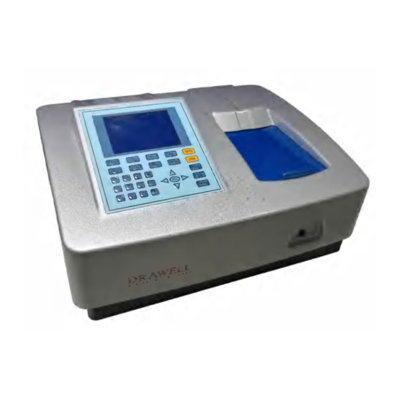
- Page 1 USER’S MANUAL For DU-8800D Series Spectrophotometers Drawell Scientific...
-
Page 3: Table Of Contents
Contents Safety ……..……………………………………………………………………. General ………………………………………………………………………. Electrical …………………………………………………………………….. Warning ………………………………………………………………………….. Performance ………………………………………………………………… Radio Interference ………………………………………………………….. Introduction ………………………………………………………………… Working Principle ………………………………………………………….. Unpacking Instructions ……………………………………………………. Specifications ……………………………………………..………………… 4 Installation ……………………………………………………………………… .5 Operation ………………………………………………………..……….…………5 Prepare the Spectrophotometer …………………………………………… 5 ………… ……………………………………… Description of keys Turn on spectrophotometer …... -
Page 5: Safety
Safety: The safety statements in this manual comply with the requirements of the HEALTH AND SAFETY AT WORK ACT, 1974. Read the following before installing and using the instrument and its accessories. This instrument should be operated by appropriate laboratory technicians. -
Page 6: Performance
Has been subjected to severe transport stresses Performance: To ensure that the instrument is working within its specification, especially when making measurements of an important nature,carry out performance checks with particular reference to wavelength and absorbance accuracy. Performance checks are detailed in this manual. Radio Interference: For compliance with the EMC standards referred to in the EC Declaration of Conformity, it is necessary that only shielded cables supplied by us are used... -
Page 7: Working Principle
Reference Light Path Sample Light Path Power switch Fuse Power socket USB Port Parallel Port Fig1 Working Principle: The spectrophotometer consists of five parts: 1) Halogen or deuterium lamps to supply the light; 2) A Monochromator to isolate the wavelength of interest and eliminate the unwanted second order radiation;... -
Page 8: Unpacking Instructions
portion of which is focused on the exit slit of the monochromator by a collimating mirror. From here the beam is passed to a sample compartment through one of the filters, which helps to eliminate unwanted second order radiation from the diffraction grating. Upon leaving the sample compartment, the beam is passed to the silicon photodiode detector and causes the detector to produce an electrical signal that is displayed on the digital display. -
Page 9: Operation
2. Place the instrument in a suitable location away from direct sunlight. In order to have the best performance from your instrument, keep it as far as possible from any strong magnetic or electrical fields or any electrical device that may generate high-frequency fields. Set the unit up in an area that is free of dust, corrosive gases and strong vibrations. -
Page 10: Description Of Keys
Fig 3 Description of keys Load data or curve saved before; 【LOAD】 Save data or curve; 【SAVE】 Set wavelength; 【SETλ】 Blank or scan the user base line; 【ZERO】 Print test results or screen 【PRINT】 Start testing or scanning sample; 【START】... -
Page 11: Turn On Spectrophotometer
Set cell position (Only available when Auto Changer used). 【CELL】 Reserved key for future Function Extending, not available now. 【HELP】 Turn on spectrophotometer Turn on spectrophotometer by pressing the Power Switch (IO)(see Fig1). The instrument starts to initiate and the steps are as below: 1.The instrument will check memory first (Fig 4), please wait or press any key to skip this step ,after positioning filter, auto-cell changer(if installed) and D2/W lamps, the screen display as Fig 4A. -
Page 12: Basic Operation
Fig 6 Fig 7 Basic operation ※ Blank There is a system baseline stored in the memory of the instrument. Usually user may not rebuild system baseline before test. Only putting the sample into the sample light path and the reference into the Reference Light Path, the result can be obtained. - Page 13 Fig 8 3. DO NOT OPEN SAMPLE COMPARTMENT LID DURING BLANKING. 4. The dark current don’t be taken after power on if you bypass the calibrating system. It is recommended to take the dark current after warm up.(See page 38). Fig 9 b.
- Page 14 Fig 10 Use numeric keypad to input wavelength (Fig 11). Fig 11 Press 【ENTER】 to change the wavelength from 656.1nm to 450.0nm,and then blank; After blanking, the screen displays as Fig Fig 12 ※ Load or delete data or curve (Take the “WL scan” test For example) Press 【3】...
- Page 15 selecting ”Yes”. Fig 13 Fig 14 Table 1 Test File Type Quantitative Curve ***.fit Quantitative Test Result ***.qua WL Scan ***.wav Kinetics ***.kin DNA/Protein ***.dna Multi WL ***.mul WL Validity Accu. Validity ※ Save data or curve (Example: Save curve in “WL scan”) ...
- Page 16 Fig 15 Table 2 representing representing representing 0,+,-,* ,/ 1,#,?,:,I 2,A,B,C,= 3,D,E,F,% 4,G,H,I,{ 5,J,K,L,} 6,M,N,O,~ 7,P,Q,R,S, 8,T,U,V,“ 9,W,X,Y,Z +/-/. -,., ※ Print test report (For example: Print the report in “Basic mode”,Fig16) Press the key【PRINT】to print the report (curve or data you have loaded or tested, Fig 17).
-
Page 17: Analyse Sample
Analyze Sample For different user’s requirements, we provide different test methods. Basic Mode Push the blank cuvette into the Reference Light Path and Main Light Path. In main menu (Fig7),press【1】 to enter “Basic mode” test . After automatically blanking, it will display as Fig 18 (automatic changer installed) or Fig 19 ( automatic changer uninstalled) and wait for the operator. - Page 18 1. Abs mode Push the blank cuvette into the Reference Light Path and Main Light Path. Press 【F2】 to select Abs mode ,Press 【ZERO】for Blanking , and then Push the sample into Main Light Path to take reading(Fig 20) 2. T% mode The operation is the same as Abs test mode but pressing【F2】...
-
Page 19: Quantitative
Fig 23 Fig 24 Print Test Report Press 【PRINT】to print test results (Fig 25). Fig 25 Quantitative Press【2】in Main Menu for “Quantitative” Test (Fig 26). Press【ESC/STOP】 to exit. Note: .If no automatic changer installed “cell #1” will disappear in Fig26. Fig 26... - Page 20 How to operate 1. Press 【F1】to select unit of concentration (Fig 27). Fig 27 2. Press【SETλ】to select correction methods and enter the wavelength. There are three correction methods (single, Isoabsorbance and 3 point, Fig 28) Note: Please refer to the Appendix B for the correction method. Fig 28 3.
- Page 21 3.2 Press 【F2】in Fig 29 to enter directly a known standard curve.Fig29A. Fig 29A The constants to be entered depend on which fitting method selected. The table below lists their relation: Fitting Method Fitting Equation constants linear fit through zero K1, r* C=K1×A Linear fit...
- Page 22 Fig 31 3.3.2 Push the blank cuvette into the Reference Light Path and Main Light Path, press【0Abs/%100T】,the instrument will step to the wavelength and blank. See Fig 32. Fig 32 3.3.3 Pull the first sample cuvette of known concentration into the light path, Press the key【START】to get values of standard curve one by one (Fig 33).
- Page 23 Fig 34 linear through zero fit Fig 35 square fit Fig 36 cubic fit Fig 37 linear fit 3.3.5 Press 【SAVE】 to save calibration if required 3.3.6 Press【ESC/STOP】to exit...
- Page 24 4. Quantitative Test Before test,the standard curve must be obtained.There are three ways for you to obtained it (a, b or c). Standard curve built up and saved in the instrument. In Fig 33 press【Load 】and then press【∧】or【∨】 to select the file with type ***.fit.
-
Page 25: Wl Scan
WL Scan Press【3】in main menu for “WL Scan” test (Fig 41). 【ESC/STOP】to exit. To load a previous curve, press【LOAD】and select a previously stored curve (.wav) Fig 41 Scan sample 1. Press 【F1】 to setup, input the start wavelength, and end wavelength by pressing the numeric keypad (Fig 42). - Page 26 Fig 43 3. Put the blank cuvette into the Reference Light Path and Main Light Path, press 【ZERO】 to scan the base line (Fig 44). Press the key 【ESC/STOP】to stop scanning; Fig 44 4. Put the sample cuvette into Main Light Path, press 【START】to scan the sample(Fig 45) 【ESC/STOP】...
- Page 27 Fig 46 5. If you want to change the scale, press 【<】 or 【>】 to change “x” scale (Fig 47), input upper limit and lower limit by pressing the numeric keypad . To change “y” scale press 【∧】 or【∨】. After these inputs the instrument will redraw the curve (Fig 48). Fig47 Fig 48 6.
- Page 28 Fig 49 1) Peak to peak, press 【 F1 】 to set “peak height” and input value by pressing the numeric keypad (Fig 50). Press 【 ∧ 】 to search the peak from left to right and press 【∨】 to search from right to left.
-
Page 29: Kinetics
Print Test Report Press 【PRINT】to print the curve you have loaded or scanned (Fig 52). Note: The report always is printed in Fig 46 Fig 52 Kinetics Press【4】in main menu for “Kinetics” (Fig 53). 【ESC/STOP】to exit. To load a previous kinetics result, press 【 LOAD 】 and select a previously stored result (.kin) - Page 30 Fig 53 Test 1. Press 【F1】 to set “Total Time”, ”Delay Time”, ”Time interval”, and input the value by pressing the numeric keypad (Fig 54). Fig 54 2. Select the test mode (“Abs” or “%T”) by pressing【F2】(Fig 55). Fig 55 3.
- Page 31 Fig 56 5. Press 【F3】to process the data, and enter “Begin Time”, ”End Time” and ”Factor” (Fig 57) and the value in I.U. will be calculated and displayed (Fig 58). The average straight line between the Begin Time and End Time will be calculated. The gradient of this line gives the rate of change of ΔA/min.
- Page 32 Save Curve Press the key 【 SAVE 】 to save curve. Note: Load/Save requires the first kinetics display page Fig. 56. Press ESC if in Search to return to the required page. Print Test Report Press the key【PRINT】 to print the curve you have loaded or scanned (Fig 59). Fig 59...
-
Page 33: Dna/Protein
DNA/Protein Press【5】in main menu for “DNA/Protein” (Fig 60). 【ESC/STOP】to exit. Note:The algorithm of the test refer to Appendix A please. Fig 60 To load previous DNA results, press (LOAD) and select a previously stored result (.dna) Test 1. To use a simpler or different algorithm, you can enter your own values for f1-f4. - Page 34 Fig 63 3. Press 【F3】to select the unit of concentration (Fig 64). Fig 64 4. Push the blank cuvette into the Reference Light Path and Main Light Path , then press 【ZERO】for blanking . 5. Pull the sample cuvette into Main Light Path, press 【START】 to test the sample.
-
Page 35: Multi Wavelength
Fig 66 Recall the default Press the key【F4】to recall the default of the f1-f4. Save Data Press the key 【SAVE】 to save data. Print Test Report Press the key【PRINT】to print the test result (Fig 67). Fig 67 Multi Wavelength Press【6】in main menu for “Multi WL” (Fig 68). 【ESC/STOP】to exit. Fig 68 To load previous Multi Wavelength results, press (LOAD) and select previously stored results (.mul) - Page 36 Test 1. Press 【F1】 to setup a group of wavelengths for testing by pressing the numeric keypad followed by 【 ENTER 】 . ( ) or ( ) to modify the inputted data Fig. 69. Press【ESC/STOP】to finish setup and exit. Note: It is recommended to enter the highest wavelength first.
- Page 37 Fig 71 5. If there is more than one sample, repeat step 4 for the next sample. Note: When the test has finished, the wavelength will go to the first 6. Press 【<)or【>】for searching. Input the sample number, the result will be displayed on the screen.
-
Page 38: Setting And Calibration
Setting and Calibration Utility Press【7】in Main menu for “Utility” (Fig 73). 【ESC/STOP】to exit. Fig 73 WL Reset Press【1】to reset wavelength (Fig74). Fig 74 Printer Press【2】to set printer (Fig 75). 【ESC/STOP】to exit. Fig 75... - Page 39 Press【1】in Fig 75 to Reset Printer. Press【2】in Fig 75 to select print port (LPT or Comm., Fig 76). Fig 76 Press【3】 in Fig 75 to select printer (HP PCL (1 colour cartridge), PCL (black mode), Epson ESC/P or Epson/P2 or above, Fig77). Fig 77 Press 【4】...
- Page 40 Lamp Press【3】to set lamp (Fig 79). 【ESC/STOP】to exit. Fig 79 1. Press【1】in Fig 79 to switch on/off D2. Fig 80. Fig 80 2. Press【2】in Fig 79 to reset usage time of D2(Fig 81). Press 【∧】or【∨】 to select “Yes” or “No”, and then press 【ENTER】. Fig 81 3.
- Page 41 Fig 82 4. Press 【4】in Fig 79 to reset usage of W (Fig 83). Press 【∧】or【∨】 to select “Yes” or “No”, and then press 【ENTER】. Fig 83 5. Press【5】 in Fig 79 to set the switch usage point of D2 and W lamp (Fig 84).
- Page 42 Fig 85 1. Press 【1】in Fig 85 to modify time by pressing the numeric keypad (Fig 86). Fig 86 2. Press 【2】in Fig 85 to modify date by pressing the numeric keypad. 3. Press【3】in Fig 85 to set the date display on the top right corner of the screen.
- Page 43 Dark Current Press 【5】In Fig73 to get dark current (Fig 88). Fig 88 Accu Validity Press 【4】In Fig73 to do Accu Validity (Fig 89). 【ESC/STOP】to exit. Fig 89 Press 【SETλ】 to set the wavelength. Press 【ENTER】to edit and input wavelength by pressing the numeric keypad (Fig 90). 【ESC/STOP】 to finish inputting and exit.
- Page 44 Fig 91 Press 【F2】to select test mode (Abs or %T, Fig 92). Fig 92 Press 【 F3 】 to set tolerance (Fig 93).Input the value by pressing the numeric keypad. Fig 93 Press【ZERO】for Blanking. Put the sample (calibrated neutral density filter) into Main Light Path. Press 【START】to check.
- Page 45 Fig 94 WL Validity Press【7】in Fig 73 to WL validity (Fig 95). 【ESC/STOP】to exit. Fig 95 2. Press 【F1】to set the standard peak. Press 【ENTER】to edit and input wavelength pressing numeric keypad (Fig96). 【ESC/STOP】to finish inputting and exit. Fig 96 3.
- Page 46 Fig 97 4. Press 【F3】 to set tolerance (Fig 98). Input the value by pressing the numeric keypad. Fig 98 5. Press 【ZERO】for blanking. 6. Put the sample (calibrated holmium liquid) into Main Light Path. Press 【START】 to check. The results will be displayed on the screen (Fig 99).
- Page 47 by PC, the screen displays as Fig 100A. Press【ESC/STOP】to exit. Fig 100 Fig 100A Beeper on/off Press【9】in Fig 73 to turn on/off the beeper Delete entire saved files Press 【 F1 】 in Fig 73 to delete entire saved files. After the delete the files, double confirm need to do.
-
Page 48: Instrument Maintenance
Instrument Maintenance To keep the instrument work in good condition, constant maintenance is needed. Daily Maintenance 1, Check the compartment After measurement, the cuvettes with sample solutions should be taken out of the compartment in time. Or the volatilization of the solution would make the mirror go moldy. -
Page 49: Spare Parts Replacement
Spare parts replacement 1, Replace the Fuse Danger! Be sure to switch off the power and unplug the socket before replacement! Step 1: Tools preparation Prepare a 3×75mm Flat Blade Screwdriver Step 2:Switch Off the power supply Switch off the power supply, and unplug the socket. Step 3: Take out the Fuse Seat Take out the Fuse Seat by the Screwdriver. - Page 50 Step 4: Remove the cover of the Lamp Chamber Unscrew the screws of the Lamp Chamber indicated in Fig.103 and remove its cover. (Fig 103) Fig 103 W Lamp Step 5: Replace Lamps D2 Lamp Connector Motor D2 Lamp Fig 104 Top View of Lamp Chamber 1) Replace D2 Lamp Unscrew the 2 screws on the D2 Flange (Indicated in the Red Circles in Fig 105), unplug the power connector(Indicated in the Red Square in...
- Page 51 Fig. 105 2) Replace W lamp Remember the direction of the filament before pull out the W lamp. Be sure that the new lamp’s filament is in the same direction as before. Pull out the defected W lamp and draw on the Cotton Glove. Insert the new W lamp as deep as possible on the Lamp Seat.
- Page 52 Fig.107 Step 8 Finish Reset the cover of the Lamps chamber and fix the screws. Reset the cover of the instrument and fix the screws. then the course finished.
- Page 53 Appendix A DNA/Protein Test Algorithm Test Name Method Calculations Displayed Wavelength(s) Parameters Units DNA MEASUREMENT =62.9 DNA: Absorbance 260nm difference concentration: =36.0 DNA/Protein μg/ml 280nm (260,280) =1552 Protein:μ 320nm Concentration Protein =757.3 (optional) g/ml concentration DNA purity Absorbance =49.1 260nm difference concentration: =3.48...
- Page 54 Appendix B A number of correction techniques can be used to eliminate or reduce interference errors. In general, if the source of the error is known and is consistent from sample to sample, the error can be eliminated. On the other hand, if the source is unknown and varies from sample to sample, the error can be reduced but not eliminated.
- Page 55 A.2 Three-point correction The three-point, or Morton-Stubbs correction uses two reference wavelengths, usually those on either side of the analytical wavelength. The background interfering absorbance at the analytical wavelength is then estimated using linear interpolation (see Figure A2).This method represents an improvement over the single-wavelength reference technique because it corrects for any background absorbance that exhibits a linear relationship to the wavelength.
- Page 56 Drawell International Technology Limited Shanghai Drawell Scientific Instrument Co.,Ltd Add : Suite 1506,Lane581 XiuChuan Rd.,PuDong New Area,Shanghai,China Tel: 0086 21 54411195 Fax: 0086 21 33823261...
- Page 57 Web : www.drawell.com.cn Email : sales01@drawell.com.cn...
Need help?
Do you have a question about the DU-8800D Series and is the answer not in the manual?
Questions and answers