Table of Contents
Advertisement
Quick Links
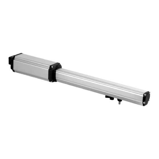
IRREVERSIBLE OPERATOR
FOR SWING GATES
AND DOORS
PM1/SC
WARNING!! Before installing, thoroughly read this manual that is an integral
part of the pack
Our products if installed by qualified personnel capable to evaluate risks,
comply with norms UNI EN 12453, EN 12445
The CE mark conforms to European directive
EEC 89/336 + 92/31 + 93/68 D.L. 04/12/1992 N. 476.
Advertisement
Table of Contents

Related Manuals for vds PM1/SC


Summary of Contents for vds PM1/SC
- Page 1 IRREVERSIBLE OPERATOR FOR SWING GATES AND DOORS PM1/SC WARNING!! Before installing, thoroughly read this manual that is an integral part of the pack Our products if installed by qualified personnel capable to evaluate risks, comply with norms UNI EN 12453, EN 12445 The CE mark conforms to European directive EEC 89/336 + 92/31 + 93/68 D.L.
- Page 2 ................PACKING CONTENTS ..... VIEW OF TYPICAL AUTOMATION AND NAMES OF COMPONENTS ..................TECHNICAL DATA ..................DIMENSIONS .......... TYPICAL CONNECTION AND CABLE SECTION ........... CONSIDERATIONS FOR INSTALLATION ..................INSTALLATION ................TROUBLESHOOTING ................SAFETY PRECAUTIONS PACKING CONTENTS 1- OPERATOR 1- KIT FASTENING PLATES AND RELATIVE ACCESSORIES 1- UNLOCKING KEY 1- CONDENSER (230Vca)
- Page 3 VIEW OF TYPICAL AUTOMATION AND NAMES OF COMPONENTS Optimal installation 1- Operator 5- Internal photocell 2- External photocell 6- Electronic control unit 3- Flashing warning light 7- Key-switch 4- Antenna 8- Remote control TECHNICAL DATA 200 Kg Max. weight of gate 2,50 mt Max.
- Page 4 DIMENSIONS TYPICAL CONNECTION AND CABLE SECTION 2X1,5mm2 (24 Vdc ) 4X1,5mm2 (230 Vca ) 2X0,75mm2 RX Photocell TX Photocell 4X0,75mm2 2X0,75mm2 4X0,75mm2 3X1,5mm2 230V Line...
- Page 5 CONSIDERATIONS FOR INSTALLATION · The installation and testing operations must be performed solely by qualified personnel in order to guarantee the proper and safe operation of the automatic gate. · The company declines any responsibility for damage caused by incorrect installations due to incompetence and/or negligence.
- Page 6 INSTALLATION OF FASTENING PLATES Fix the back plate to the pillar.(FIG. 1) Anchor the rear part of the piston (FIG. 1) to the plate and fasten it firmly ( FIG. 2) (FIG. 2) (FIG. 3) Warning! When establishing the height off the ground at which to fasten the plate (FIG.1) onto the post, keep in mind the height at which the plate will be fastened (FIG.3) for anchoring the piston to the gate and that the plate must be fastened 50 mm below that on the post to obtain horizontal levelling.
- Page 7 TROUBLESHOOTING SOLUTION PROBLEM PROBABLE CAUSE 230 volt mains voltage Check master switch absent Check for any STOP selectors or commands. Emergency STOP present If not used, check jumper On giving a command with on STOP contact input on the remote the control board control or with the key-switch, the gate...
- Page 8 Products are installed. The data and images are for guidance only VDS reserves the right to change at any time characteristics of the products described in its sole discretion, without notice. Via Circolare p.i.p. N° 10 65010 Santa Teresa di Spoltore (PE) - ITALY Tel.
Need help?
Do you have a question about the PM1/SC and is the answer not in the manual?
Questions and answers