Sign In
Upload
Download
Table of Contents
Contents
Add to my manuals
Delete from my manuals
Share
URL of this page:
HTML Link:
Bookmark this page
Add
Manual will be automatically added to "My Manuals"
Print this page
×
Bookmark added
×
Added to my manuals
Manuals
Brands
vds Manuals
Gate Opener
PHV 240
Instruction manual
vds PHV 240 Instruction Manual
Hydraulic gate
Hide thumbs
1
2
3
4
5
6
7
8
9
10
11
Table Of Contents
12
page
of
12
Go
/
12
Contents
Table of Contents
Bookmarks
Table of Contents
Declaration of Conformity
Important Safety Instructions
Technical Data
Work Area
Mounting Instructions
Blocking Function
Box Contents
Spare Parts
Advertisement
Quick Links
1
Mounting Instructions
Download this manual
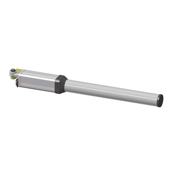
INSTRUCTION MANUAL
HYDRAULIC GAT E
PHV 240-PHV 360
Ed1. 14/12/09 (Italiano)
Table of
Contents
Previous
Page
Next
Page
1
2
3
4
5
Advertisement
Table of Contents
Need help?
Do you have a question about the PHV 240 and is the answer not in the manual?
Ask a question
Questions and answers
Related Manuals for vds PHV 240
Gate Opener vds PHV 360 Instruction Manual
Hydraulic gate (12 pages)
Gate Opener vds PH 275 R Installation Manual
(8 pages)
Gate Opener vds PM1/SC Technical Installation Manual
Irreversible operator for swing gates and doors (8 pages)
Gate Opener vds PM/PM1 Technical Installation Manual
Operator for swing gates and doors (8 pages)
Gate Opener vds PM400 Technical Installation Manual
Operator for swing gates and doors (41 pages)
Gate Opener vds AG-Future Technical Installation Manual
Motoreducer for sliding gates (50 pages)
Gate Opener vds UNDER 250 Technical Installation Manual
(13 pages)
Gate Opener vds LINEAR-11 Technical Installation Manual
Irreversible operator for swing gates and doors (8 pages)
Gate Opener vds TOM 8000 Quick Start Manual
Operator three-phase for sliding gate 8,0 - 16,0 tom intensive use (12 pages)
Gate Opener vds GYS150M Use And Installation Manual
(14 pages)
Gate Opener vds AMICO 400DG Technical Installation Manual
Irreversible operator for swing gates and doors (8 pages)
This manual is also suitable for:
Phv 360
Table of Contents
Print
Rename the bookmark
Delete bookmark?
Delete from my manuals?
Login
Sign In
OR
Sign in with Facebook
Sign in with Google
Upload manual
Upload from disk
Upload from URL


Need help?
Do you have a question about the PHV 240 and is the answer not in the manual?
Questions and answers