Advertisement
Available languages
Available languages
Quick Links
English
M
OUNTING THE UNIT
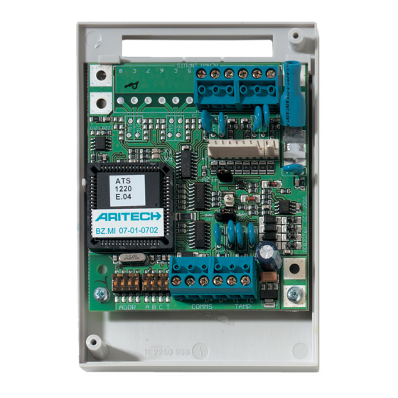
Mount the 4/8-zones Data Gathering Panel PCB in any existing ATS series
enclosure that supports the BB format.
C
J1
ONNECTIONS
12 VDC power supply. It is recommended that where the distance
between an ATS1220 and the nearest device is more than 100
+
meters, a separate power supply be used.
-
COMMS
Positive and negative data connection of the system databus.
D+
Units can be up to 1.5 km from the 4-lift DGP or the ATS control
D-
panel, depending on the cable used. See the ATS control panel
installation guide for details.
T
TAMP
Connect the enclosure tamper switch across these terminals
C
(Tamper switch requires normally open contacts.)
L
INKS
Earth connection. Earth wires from all pieces of equipment must
be earthed at one system earth. For further detail see the ATS
control panel installation guide
DGP
DIPSWITCH SETTINGS
switches 1 to 4 are used to identify the DGP number.
ADDR
Dip
ABCT
T
Set switch T on if this device is the last device on the system
databus. For more details see the ATS control panel installation
guide.
A,C
Not in use
B
ON - ATS1811 8-way relay card or ATS1820 16-way open
collector card connected to J4.
OFF - no ATS1811 or ATS1820 connected to J4. Use this
setting also if an ATS1810 is connected to J4.
105066 г. Москва, ул. Спартаковская, д.11, корп. 1,
тел. (095) 787-33-42, (095) 937-90-57; факс (095) 937-90-55
.
Model ATS1210/1220
TX
RX
LED'
S
RX
LED flashes to indicate polling data is being received on the system
databus from the ATS control panel. If the LED does not flash the control
panel is not operational or the databus is faulty (usually cabling).
TX
LED flashes to indicate the DGP is replying to polling from the ATS
control panel. If the RX LED flashes but the TX LED does not, it
indicates that the DGP is not programmed to be polled in the control
panel or that it is addressed incorrectly.
Z
ONE NUMBERING
A 4/8-zones DGP can have four or eight zones connected to it.
There are 16 zones allocated to every DGP address. Only zones 1 to 4 or 1 to
8 can be used when an ATS1210/1220 is allocated a DGP number. Zones not
available (5 - 16) or (8-16) should be programmed as type 0 (zone disabled)
in the Zone database.
Control panel
1 – 16
DGP1
17 - 32
DGP2
33 - 48
DGP3
49 - 64
DGP4
65 - 80
DGP5
81 - 96
DGP6
97 - 112
DGP7
113 - 128
Note 1: The ATS1210/1220 cannot be expanded to provide additional zones.
J4
OUTPUTS
J2
Each zones requires a 4k7 end-of-line resistor (1 or 2
depending on single or dual zone monitoring programmed in
ATS control panel).
J4
+12 VDC supply and open collector or data output for
Output
connection to ATS 1810, ATS 1811 and ATS 1820 output
cards via 10-way cable supplied with the output card. Up to
sixteen outputs are available with 8-way or 16-way open
collector cards (4-way and 8/16-way output cards cannot be
used together on the same DGP)
1
4/8-Zones DGP
DGP8
129 - 144
DGP9
145 - 160
DGP10
161 - 176
DGP11
177 - 192
DGP12
193 - 208
DGP13
209 - 224
DGP14
225 - 240
DGP15
241 - 256
Advertisement

Related Manuals for Aritech ATS1210


Summary of Contents for Aritech ATS1210
- Page 1 TAMP Connect the enclosure tamper switch across these terminals 8 can be used when an ATS1210/1220 is allocated a DGP number. Zones not (Tamper switch requires normally open contacts.) available (5 - 16) or (8-16) should be programmed as type 0 (zone disabled) in the Zone database.
- Page 2 Для каждого адреса АМР выделено по 16 зон. Только зоны с 1 по 4 или с TAMP Подключите тампер контакт корпуса через эти контакты 1 по 8 могут быть задействованы при использовании модулей ATS1210 / (Тампер контакт должен быть нормально разомкнутым.) ATS1220 из выделенных для данного адреса АМР. Недоступные зоны (5 - 16) или...
- Page 3 Model ATS1210/1220 Т ECHNICAL SPECIFICATIONS ЕХНИЧЕСКИЕ ХАРАКТЕРИСТИКИ Supply Voltage Напряжение питания 10,5 - 13,8 V DC. Current consumption Потребляемый ток 53 mA max. Dimensions (H x W) (size B board). Размеры (В x Ш) (плата типа B). 90 x 80 mm Operating temperature Рабочая...
Need help?
Do you have a question about the ATS1210 and is the answer not in the manual?
Questions and answers