Advertisement
Available languages
Available languages
Quick Links
1 2 3 4
J2
IN OUT D- D+
English
M
OUNTING THE UNIT
The unit is supplied as a kit consisting of a keypad and separate electronics. It
can be mounted on the surface, or if required, installed in a custom enclosure.
Note:
Mount the unit at an acceptable height so that it is easy to
operate without needing to reach up, and the LED's can be easily
seen.
C
ONNECTING CONTROL PANEL TO KEYPAD
Refer to the ATS control panel installation guide for instructions.
RAS
(
DIP SWITCH SETTINGS
FIGURE
SW1 "ADDRESS" dip switches 1 to 4 are used to identify this RAS number.
LED'
(
)
S
FIGURE
TX
LED flashes to indicate the arming station (RAS) is replying to polling
from the ATS control panel.
LED I
NDICATIONS ON KEYPAD
(L1) ACCESS (Disarmed) Illuminates when at least one of the areas
assigned to the arming station is disarmed, and when a PIN is
used to open a door, the LED flashes for the unlock time.
(L2) ALM
(Alarm) Illuminates when an alarm has occurred in one of the
areas assigned to the arming station.
•
(L3) RDY
When connected to the control panel, it illuminates when
the area is ready to be armed (system clear). ie. all inputs
normal, or
.
105066 г. Москва, ул. Спартаковская, д.11, корп. 1,
тел. (095) 787-33-42, (095) 937-90-57; факс (095) 937-90-55
ON
1
2
RAS 1
ON
1
2
RAS 5
ON
1
2
RAS 9
ON
- +
1
2
RAS 13
(
)
FIGURE
)
(
)
FIGURE
Dipswitches
ON
ON
ON
3
4
1
2
3
4
1
2
3
4
1
2
3
4
RAS 2
RAS 3
RAS 4
ON
ON
ON
3
4
1
2
3
4
1
2
3
4
1
2
3
4
RAS 6
RAS 7
RAS 8
ON
ON
ON
3
4
1
2
3
4
1
2
3
4
1
2
3
4
RAS 10
RAS 11
RAS 12
ON
ON
ON
3
4
1
2
3
4
1
2
3
4
1
2
3
4
RAS 14
RAS 15
RAS 16
(L4) SECURE Illuminates when the area is armed.
When All LED's are flashing, the arming station is not being polled.
C
ONNECTIONS
+
Power supply. If the distance between the arming station and the
control panel does not exceed 100m, then the arming station can be
-
powered using the Comms + and – from the control panel. Otherwise
use AUX PWR from DGP's or an auxiliary power supply.
D+
Data positive and data negative connection of the databus.
D -
Remote units can be up to 1.5 km from the ATS control panel.
IN
A request to exit button (normally open, momentary push-button switch)
can be connected across "IN" and "-". When pressed, this button
controls the request to exit function.
OUT Open collector output, 50 mA maximum. It is the first output of the
output control group that is assigned to this arming station.
L
(
INKS
FIGURE
GND
TERM
C
ONNECTION FROM ELECTRONICS TO KEYPAD
Via a standard cable supplied with this product
1
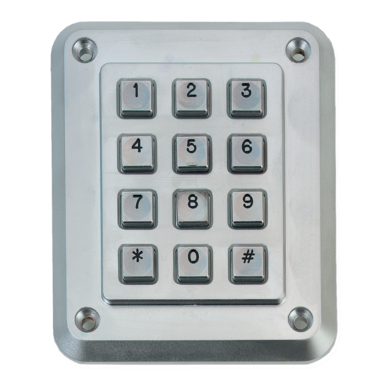
Model ATS1155
Access
ALM
RDY
Secure
Heavy Duty 4 LED RAS
•
When connected to an 4-door/4-lift DGP, it illuminates
when ready to accept a PIN code.
J2
(
)
TERMINALS
FIGURE
)
Must remain fitted.
Fitted if this device is the last device on the system databus.
For more details see the ATS control panel installation guide.
J10
ATS4000
(
)
FIGURE
Advertisement

Related Manuals for Aritech ATS1155


Summary of Contents for Aritech ATS1155
- Page 1 Model ATS1155 Dipswitches ATS4000 RAS 1 RAS 2 RAS 3 RAS 4 Access Secure 1 2 3 4 RAS 5 RAS 6 RAS 7 RAS 8 RAS 9 RAS 10 RAS 11 RAS 12 IN OUT D- D+ RAS 13...
- Page 2 Модель ATS1155 Руководство по установке Русский Вандалозащищенная клавиатура с 4 светодиодами • М В случае подключения к 4-х дверному/лифтовому ОНТАЖ контроллеру, свечение светодиода означает готовность к В комплект поставки входит клавиатура и отдельная электронная плата. приему ПИН кода. Клавиатура может монтироваться на поверхности или, при...
- Page 3 ATS1155 ODEL Т ECHNICAL ЕХНИЧЕСКИЕ ДАННЫЕ Power supply Напряжение питания 10,5 - 13,8 VDC. Current consumption Потребление тока 70 mA max. Dimensions (H x W) Размеры (В x Ш) 118 mm x 75 mm. Operating temperature: Рабочая температура: 0°C to + 50°C.
Need help?
Do you have a question about the ATS1155 and is the answer not in the manual?
Questions and answers