
Related Manuals for Bender EDS440-LAF-4


Summary of Contents for Bender EDS440-LAF-4
- Page 1 Manual EDS440-L/-S EDS441-L/-S EDS441-LAB-4 EDS440-LAF-4 Insulating fault locator to locate insulation faults in ungrounded DC, AC and three-phase power supplies (IT systems) EDS44x_D00201_07_M_XXEN/06.2020...
- Page 2 E-Mail: info@bender.de Web: www.bender.de Customer service Service-Hotline: 0700-BenderHelp (Telephone and Fax) Carl-Benz-Straße 8 • 35305 Grünberg • Germany © Bender GmbH & Co. KG Tel.:+49 6401 807-760 All rights reserved. Fax:+49 6401 807-629 Reproduction only with permission of the publisher.
-
Page 3: Table Of Contents
EDS440-LAF-4 ........ - Page 4 Table of contents Table of contents 6.4 Alarm messages ........... 27 10.
- Page 5 Table of contents 13. Technical data ................52 13.1 Tabular data ........... . . 52 13.2 Standards and certifications .
-
Page 6: Important Information
1.2 Technical support 1.2.1 End customer support and advice This manual is intended for qualified personnel working in electrical Technical support by phone or e-mail for all Bender products engineering and electronics! • Questions concerning specific customer applications • Commissioning •... -
Page 7: Training Courses
• Old electrical and electronic equipment from users other than private households Sale and delivery conditions can be obtained from Bender in printed or electronic format. which was introduced to the market after 13 August 2005 must be taken back by the manufacturer and disposed of properly. -
Page 8: Safety Instructions
Part of the device documentation in addition to this manual is the enclosed "Safety in- to the life and limb of the user or third parties and/or result in damage to the EDS44x or structions for Bender products". other property. -
Page 9: Requirements For Reliable Insulation Fault Location
12 measuring current transformers can be connected for each EDS44x. Up to 50 EDS44x 2.6 Periodic verification can be linked via BS bus (Bender sensor bus, RS-485 interface with BS protocol) and there- The EDS system monitors itself during operation. -
Page 10: Function
3. Function Function 3.1 Features 3.1.4 System properties • Universal system concept 3.1.1 Areas of application • Modular design, therefore easily adjustable to the given circumstances • Insulation fault location in AC, 3(N)AC and DC IT systems • Measuring current transformers available in various sizes and versions •... - Page 11 ◊ WS… W/WS 8000 Type A ◊ ◊ Type W…AB ◊ CTAF…SET Type A ◊ 3.1.5.3 Other Bender devices Device EDS440-L EDS440-S EDS441-L EDS441-S EDS441-LAB EDS440-LAF COM460 COM465 IOM441-S CP700 MK2430 IRDH575 iso685-x-p BS bus BB bus BS bus BB bus...
-
Page 12: Operating Principle Of The Eds System
Function Function 3.2 Operating principle of the EDS system For further information, refer to the data sheet "Technical aspects main catalogue part 1" in the chapter "Technical aspects when using insulation fault lo- When an insulation monitoring device detects the occurrence of an insulation fault, it cation systems". -
Page 13: Schematic Diagram Eds System
Function Function 3.3 Schematic diagram EDS system Legend EDS44x Insulation fault locator iso685-D-P Insulation monitoring device with an integrated locating current injector Voltage source IT system Supply voltage Measuring current transformers Locating current Insulation fault downstream of the measuring current transformer Protective earth conductor or equipotential bonding conductor BS bus BS bus for device communication... -
Page 14: Device Overview
4. Device overview Device overview 4.1 External dimensions EDS44x-x and IOM441-S 4.2 View EDS440-S l1 l2 l3 l4 l5 l6 l7 l8 l9 l10 l11 l12 k1 k2 k3 k4 k5 k6 k7 k8 k9 k10 k11 k12 11 12 EDS440 ISOSCAN®... -
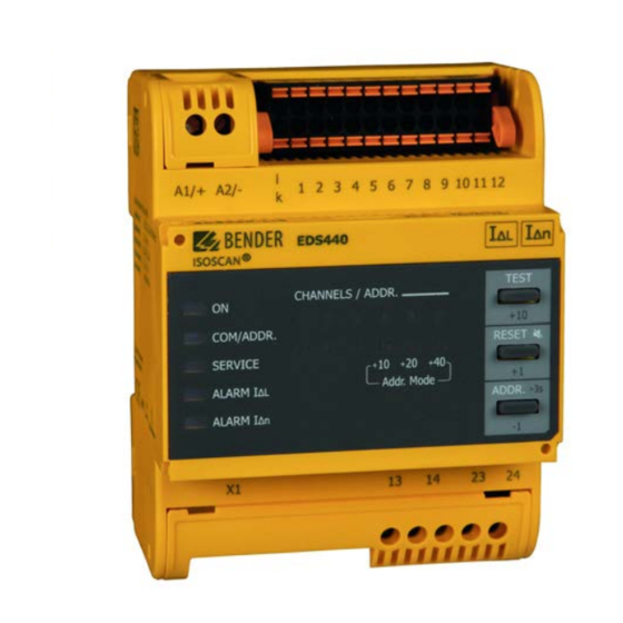
Page 15: Connections And Control Panel Eds44X-L
Device overview Device overview 4.4 Connections and control panel EDS44x-L 4.5 Connections and control panel EDS44x-S A1/+ A2/- k1 - 12 | l1 - 12 A1/+ A2/- Connection 9 10 11 12 2 3 4 5 9 10 11 12 Connection Supply current transformers... -
Page 16: Mounting
5. Mounting Mounting 5.1 General instructions 5.2 Installation clearances Only qualified personnel are permitted to carry out the work necessary 20 mm to install, commission and run a device or system. l1 l2 l3 l1 l2 l3 l1 l2 l3 l1 l2 l3 l1 l2 l3 l1 l2 l3... -
Page 17: Screw Mounting
Mounting Mounting 5.3 Screw mounting 5.4 DIN rail mounting 1. Fix the two mounting clips provided with the device manually or using a tool as 1. Fix one of the provided mounting clips manually or using a tool as illustrated below. illustrated below. -
Page 18: Connection Of The Bb Bus
5.5 Connection of the BB bus 5.6 Connection to the voltage supply The BB bus is an interface that enables Bender devices to communicate with each other. = AC/DC 24...240 V The BB bus can be used with an ISOMETER® and a maximum of two EDS44x or one EDS44x-S and one IOM44-S. -
Page 19: Connection Of The X1 Interface
Mounting Mounting 5.7 Connection of the X1 interface 5.9 BS bus termination I1 I2 A 13 14 23 24 13 14 23 24 24 2 Input 1 M+ Dig. current output Activating a terminating resistor to define the first and the last device in the bus system. Input 2 Ground RS-485 A (input) -
Page 20: Connection Of W
Mounting Mounting 5.10.1 Connection of W…, WR…, WS… series measuring current 5.10.2 Connection of W…AB series measuring current transformers to transformers EDS441-LAB-4 For insulation fault location, the measuring current transformers of the W… (closed), WR… (rectangular) and WS… (split-core) series are used. W...AB CTAC 1 CTAC 2... -
Page 21: Connection Of Ctaf
5.10.3 Connection of CTAF…SET series measuring current transformers to EDS440-LAF-4 For insulation fault location, the measuring current transformers of the CTAF…SET series are used. CTAF CTAF CTAF A1 A2 EDS440-LAF-4 Locating current The EDS440-LAF-4 operates exclusively with a locating current > 10 mA. EDS44x_D00201_07_M_XXDE/06.2020... -
Page 22: Wiring Diagram To Dc System With Isometer® Iso685-D-P
Mounting 5.11 Wiring diagram to DC system with ISOMETER® iso685-D-P L– Load Load back-up back-up l1 l2 l3 l4 l5 l6 l7 l8 l9 l10 l11 l12 A1/+ A2/- k1 k2 k3 k4 k5 k6 k7 k8 k9 k10 k11 k12 L1/+ L3/- KE E... -
Page 23: Wiring Diagram To Ac System With Isometer® Iso685-D-P
Mounting 5.12 Wiring diagram to AC system with ISOMETER® iso685-D-P Load Load back-up back-up l1 l2 l3 l4 l5 l6 l7 l8 l9 l10 l11 l12 A1/+ A2/- L1/+ L3/- KE E k1 k2 k3 k4 k5 k6 k7 k8 k9 k10 k11 k12 9 10 11 12 EDS440 ISOSCAN®... -
Page 24: Wiring Diagram To 3(N)Ac System With Isometer® Iso685-D-P
Mounting 5.13 Wiring diagram to 3(N)AC system with ISOMETER® iso685-D-P Load Load back-up back-up l1 l2 l3 l4 l5 l6 l7 l8 l9 l10 l11 l12 A1/+ A2/- k1 k2 k3 k4 k5 k6 k7 k8 k9 k10 k11 k12 L1/+ L3/- KE E... - Page 25 Mounting 5.14 Connection example: ISOMETER® iso685-D-P, EDS440-S, IOM441-S and EDS440-L External signal Load Load Load Load back-up back-up l1 l2 l3 l4 l5 l6 l7 l8 l9 l10 l11 l12 k1 k2 k3 k4 k5 k6 k7 k8 k9 k10 k11 k12 A1/+ A2/- L1/+ L3/-...
-
Page 26: Display And Alarm Messages
6. Display and alarm messages Display and alarm messages 6.1 Operating and display elements EDS44x-S The "ON" LED flashes until the device is ready for operation during power up. The "ON" LED lights up when the device is turned on. A current transformer connection test is carried out every hour. -
Page 27: Standard Display In The Operating Mode
Display and alarm messages Display and alarm messages 6.3 Standard display in the operating mode 6.4 Alarm messages The values of the EDS44x-L are mainly displayed via the connected ISOMETER® and the Alarm messages of the EDS44x-L are directly indicated on the control panel of the device, values of the EDS44x-S are only displayed via the connected ISOMETER®. -
Page 28: Connection Fault Of The Current Transformers
In the event of a device error, an error code is additionally displayed on the correspond- 6.4.5 Device error, failure BS bus master ing ISOMETER®. Please have it at hand for the Bender service. Service and COM LED light up simultaneously and continuously. -
Page 29: Error Message
Display and alarm messages Display and alarm messages 6.4.6 Error message In the event of an error message, the LED of the respective channel flashes. An error can, for example, be caused by low-frequency residual currents, external magnetic fields, etc. TEST TEST CHANNELS / ADDR. -
Page 30: Commissioning
7. Commissioning Commissioning Risk of overcurrent! 7.2 Switching on Devices connected to the analogue output must have a suitable protec- 1. Switch on the supply voltage of all devices connected to the BS bus or the BB bus. tive circuit against overcurrent to protect the device in the event of a de- First, the "ON"... -
Page 31: Steps For Commissioning Isometer® And Eds44X
Commissioning Commissioning 7.3 Steps for commissioning ISOMETER® and EDS44x Inbetriebnahme-Schema iso685-x-P mit EDS44x Inbetriebnahme Inbetriebnahme Inbetriebnahme Inbetriebnahme Inbetriebnahme Inbetriebnahme ISOMETER® EDS44x ISOMETER® mit EDS44x ISOMETER® EDS44x ISOMETER® mit EDS44x Ggf. Gruppenein-stellun- Funktionsprüfung mit Gerät anschließen gemäß Gerät und Mess-stromwan- Versorgungsspannung gen anpassen geeignetem Widerstand Anschlussbild und Gerä-te-... -
Page 32: Device Communication
8.1.4 Leitungsführung Die optimale Leitungsführung für den BS-Bus ist die reine Linienstruktur. Stichleitungen Der BS-Bus dient zur Erweiterung von Bender-Messgeräten (z. B. ISOMETER®). Dabei han- zu einzelnen Geräten von maximal 1 m Länge sind zulässig. Diese Stichleitungen werden delt es sich um eine RS-485-Schnittstelle mit einem speziell für Bender-Geräte entwi-ck- nicht terminiert. -
Page 33: Operation
9. Operation Operation 9.1 Reading out and setting the BS address 9.1.2 Setting a BS address Activate TEST If the BS address is set to 0, the device goes into the trigger mode "au- CHANNELS / ADDR. address input to". See "Trigger function"... -
Page 34: Extended Address Range (Offset = 80)
Operation Operation 9.1.3 Extended address range (offset = 80) 9.2 Display and change of transmission protocols Activate 9.2.1 Displaying the current transmission protocol TEST CHANNELS / ADDR. address input TEST COM/ADDR. CHANNELS / ADDR. RESET SERVICE COM/ADDR. RESET Addr. Mode ALARM ∆... -
Page 35: Resetting Saved Alarm Messages (Reset Button)
Operation Operation 9.3 Resetting saved alarm messages (RESET button) The EDS44x-L responds as follows: • "ALARM I " LED and "ALARM I " LED light up. ΔL Δn If the fault memory is enabled, the alarm state will remain, even after the cause of the fault •... -
Page 36: Settings
Afterwards, the EDS system is permanently active, regardless of the • 25 mA for EDS440-x/EDS440-LAF-4 insulation value and the alarm message of the ISOMETER®. The EDS system can be stopped manually at any time using the shortcut button or via the •... -
Page 37: Fault Memory
Settings Settings 10.1.3 Fault memory 10.2.1.2 Digital input mode Faults that only occur temporarily can be saved in the ISOMETER®. The operating mode for the digital input can be set to the following values: •Active high • on After eliminating the cause of fault, alarm messages remain stored until a An event is carried out on the rising edge of the digital input (low to RESET is carried out. -
Page 38: Digital Outputs Of The Eds44X-L
Settings Settings 10.2.2 Digital outputs of the EDS44x-L 10.2.2.4 Functional description The EDS44x-L features a digital current output (0 or 20 mA), a buzzer and relays, which Up to three functions can be assigned to one output. The functions are linked to an OR can be configured individually. -
Page 39: Factory Settings
Settings Settings 10.3 Factory settings Parameter Value Parameter Value General information Buzzer Response value insulation fault location (I 0.5 mA (EDS441-x, EDS441-LAB) Buzzer test Δ 5 mA (EDS440-x) Buzzer function 1 10 mA (EDS440-LAF) Buzzer function 1 Response value residual current measurement 10 A (EDS440-x) Buzzer function 1 1 A (EDS441-x, EDS441-LAB) -
Page 40: Alarm Messages
ISOMETER® • Read out error code on the corresponding page 28 • Contact Bender service • "SERVICE" LED lights up Connection fault of the current transformers • Replace defective measuring current transformers see "Connection fault of the •... -
Page 41: Diagrams
12. Diagrams Diagrams 12.1 Response sensitivity curves The following characteristic curves allow easy determination of a practical response value for the insulation monitoring device and the EDS44x. Proceed as follows: System type, system voltage, system frequency, leakage capacitance and locating cur- 1. -
Page 42: Characteristic Curves Eds440 For 3Ac Systems
Diagrams Diagrams 12.1.1 Characteristic curves EDS440 for 3AC systems 3AC 500V 3AC 230V 2mA 3AC230V 2mA 3AC500V [IL=10mA] [IL=10mA] 5mA 3AC230V 5mA 3AC500V [IL=10mA] [IL=10mA] 10mA 3AC230V 10mA 3AC500V [IL=25mA] [IL=25mA] 1000 1000 Ce [μF] Ce [μF] 3AC 400V 3AC 690V 2mA 3AC400V 2mA 3AC690V [IL=10mA]... -
Page 43: Characteristic Curves Eds440 For Ac Systems
Diagrams Diagrams 12.1.2 Characteristic curves EDS440 for AC systems AC 42V AC 230V 2mA AC42V 2mA AC230V [IL=10mA] [IL=10mA] 5mA AC42V 5mA AC230V [IL=10mA] [IL=10mA] 10mA AC42V 10mA AC230V [IL=25mA] [IL=25mA] 1000 1000 Ce [μF] Ce [μF] AC 110V AC 400V 2mA AC110V 2mA AC400V [IL=10mA]... -
Page 44: Characteristic Curves Eds440 For Dc Systems
Diagrams Diagrams 12.1.3 Characteristic curves EDS440 for DC systems DC 24V DC 110V 2mA DC24V 2mA DC110V [IL=10mA] [IL=10mA] 5mA DC24V 5mA DC110V [IL=10mA] [IL=10mA] 10mA DC110V 10mA DC24V [IL=25mA] [IL=25mA] 1000 1000 Ce [μF] Ce [μF] DC 60V DC 220V 2mA DC60V 2mA DC220V [IL=10mA]... - Page 45 Diagrams Diagrams DC 300V DC 1000V 2mA DC300V 2mA DC1000V [IL=10mA] [IL=10mA] 5mA DC300V 5mA DC1000V [IL=10mA] [IL=10mA] 10mA DC300V 10mA DC1000V [IL=25mA] [IL=25mA] 1000 1000 Ce [μF] Ce [μF] DC 600V 2mA DC600V [IL=10mA] 5mA DC600V [IL=10mA] 10mA DC600V [IL=25mA] 1000 Ce [μF]...
-
Page 46: Characteristic Curves Eds441 For Ac Systems
Diagrams Diagrams 12.1.4 Characteristic curves EDS441 for AC systems AC 42V AC 230V 1200 0,2mA AC42V 0,2mA AC230V [IL=2,5mA] [IL=2,5mA] 1000 0,5mA AC42V 0,5mA AC230V [IL=2,5mA] [IL=2,5mA] 1,0mA AC42V 1,0mA AC230V [IL=2,5mA] [IL=2,5mA] 1000 1000 Ce [μF] Ce [μF] AC 110V 0,2mA AC110V [IL=2,5mA] 0,5mA AC110V... -
Page 47: Characteristic Curves Eds441 For Dc Systems
Diagrams Diagrams 12.1.5 Characteristic curves EDS441 for DC systems DC 24V DC 110V 0,2mA DC24V 0,2mA DC110V [IL=2,5mA] [IL=2,5mA] 0,5mA DC24V 0,5mA DC110V [IL=2,5mA] [IL=2,5mA] 1,0mA DC24V 1,0mA DC110V [IL=2,5mA] [IL=2,5mA] 1000 1000 Ce [μF] Ce [μF] DC 60V DC 220V 1200 0,2mA DC60V 0,2mA DC220V... -
Page 48: Characteristic Curves Eds441-Lab For Ac Systems
Diagrams Diagrams 12.1.6 Characteristic curves EDS441-LAB for AC systems AC 42V 0,5mA AC42V [IL=1,8mA] 1000 Ce [μF] AC 230V 0,5mA AC230V [IL=1,8mA] 1000 Ce [μF] EDS44x_D00201_07_M_XXDE/06.2020... -
Page 49: Characteristic Curves Eds441-Lab For Dc Systems
Diagrams Diagrams 12.1.7 Characteristic curves EDS441-LAB for DC systems DC 220V DC 48V 0,5mA DC220V 0,5mA DC48V [IL=1,8mA] [IL=1,8mA] 1000 1000 Ce [μF] Ce [μF] DC 110V 0,5mA DC110V [IL=1,8mA] 1000 Ce [μF] EDS44x_D00201_07_M_XXDE/06.2020... -
Page 50: Response Values Eds440-Laf For Dc Systems Up To A System Leakage Capacitance Of Max. 100 Μf
Diagrams Diagrams 12.1.8 Response values EDS440-LAF for DC systems up to a system leakage capacitance of max. 100 μF: Nominal voltage Max. insulation fault R DC 60 V 2 kOhm 5 kOhm DC 110 V 10 kOhm DC 220 V DC 300 V 15 kOhm 30 kOhm... -
Page 51: Fault Curve Eds440
Diagrams Diagrams 12.2 Fault curve EDS440 12.3 Fault curve EDS441 An insulation fault location beyond the grey area causes an error message. The EDS44x-L An insulation fault location beyond the grey area causes an error message. The EDS44x-L indicates error messages via flashing LEDs indicates error messages via flashing LEDs (refer to "Service and COM LED light up simultaneously and continuously."... -
Page 52: Technical Data
13. Technical data Technical data 13.1 Tabular data Response value residual current measurement (I ) EDS441................... 100 mA…1 A ∆n Relative uncertainty (I ) EDS44x (42…60 Hz)..........................±5 % ∆n Insulation coordination acc. to IEC 60664-1/IEC 60664-3 Relative uncertainty (I ) EDS44x (61…1000 Hz)......................... -20…0 % ∆n Definitions Hysteresis ...................................... - Page 53 Technical data Technical data Digital inputs Environment/EMC Number........................................2 EMC ..................................... IEC 61326-2-4 Operating mode, adjustable........................... active high, active low Ambient temperatures Function.....................................none, test, reset Operating temperature..............................-25 °C… +55 °C Voltage level..........................Low DC -5…5 V, High DC 11…32 V Transport..................................
-
Page 54: Standards And Certifications
= Residual current effect of > 100 mA results in a greater relative uncertainty. EDS441W-L-4 AC/DC 24…240 V 0.2…1 mA B91080205W EDS441-LAB-4 AC/DC 24…240 V 0.2…1 mA B91080207 EDS441W-LAB-4 AC/DC 24…240 V 0.2…1 mA B91080207W EDS440-LAF-4 AC/DC 24…240 V 10 mA B91080209 * Absolute values EDS44x_D00201_07_M_XXDE/06.2020... -
Page 55: Accessories
Technical data Technical data 13.3.2 Accessories Alternative measuring current transformers from the Bender program Type Internal diameter/mm Design type Art. No. Description Art. No. W10/600 circular B911761 EDS440/441 mechanical accessories comprising: B91080903 W0-S20 circular B911787 terminal cover and 2 mounting clips (scope of delivery) - Page 56 Technical data Technical data For further information regarding the measuring current transformers, refer to the data sheets. Measuring current transformers for EDS441-LAB Bender measuring current transformers Type Internal diameter/mm Design type Art. No. W20AB circular B98080008 W35AB circular B98080016 W60AB...
-
Page 57: Index
Index Alarm messages 27 Response sensitivity 41 Accessories 55 Operating and display elements EDS…-L 26 RS-485 interface 32 Alarm messages 27, 40 Operating and display elements EDS…-S 26 Standard display EDS…-L 27 Schnittstellen Standard display EDS…-S 27 BB bus 18 BS-Bus 32 Bedienung Settings 36... - Page 58 Bender GmbH & Co. KG Customer service Postbox 1161 • 35301 Grünberg • Germany Service hotline: 0700-BenderHelp (Telephone und Fax) Londorfer Straße 65 • 35305 Grünberg • Germany Carl-Benz-Straße 8 • 35305 Grünberg • Germany Tel.: +49 6401 807-0 Tel.:...
Need help?
Do you have a question about the EDS440-LAF-4 and is the answer not in the manual?
Questions and answers