Sign In
Upload
Download
Table of Contents
Contents
Add to my manuals
Delete from my manuals
Share
URL of this page:
HTML Link:
Bookmark this page
Add
Manual will be automatically added to "My Manuals"
Print this page
×
Bookmark added
×
Added to my manuals
Manuals
Brands
Bender Manuals
Test Equipment
UNIMET 1000ST
Operating manual
Bender UNIMET 1000ST Operating Manual
Test systems for electrical safety
Hide thumbs
1
2
Table Of Contents
3
4
5
6
7
8
9
10
11
12
13
14
15
16
17
18
19
20
21
22
23
24
25
26
27
28
29
30
31
32
33
34
35
36
37
38
39
40
41
42
43
44
45
46
47
48
49
50
51
52
53
54
55
56
57
58
59
60
61
62
63
64
65
66
67
68
69
70
71
72
73
74
75
76
77
78
79
80
81
82
83
84
85
86
87
88
89
90
91
92
93
94
95
96
97
98
99
100
page
of
100
Go
/
100
Contents
Table of Contents
Bookmarks
Table of Contents
Table of Contents
Effective Use of this Manual
About the Operating Manual
Technical Support
Explanations of Symbols and Notes
Overview of Chapters
Safety Instructions
Delivery
Intended Use
Qualified Personnel
General Safety Instructions
Warranty and Liability
Guarantee
System Description
Areas of Application
Function
Tests Conforming to Standards
System Components
Operating Elements
Operation and Setting
Unpacking
Commissioning
Setting up
Connection of Keypad Purchased as an Optional Accessory
Switching on
Switching off
Principle of Operation
Calling up Functions
Entering Text and Numbers
How to Use the TM1000 Keypad Module
How to Use the On-Screen Keypad
Selecting Catalogue Entries
Main Menu
System Administration
Basic Settings
Log in Test Engineer
Interfaces
Interface
Barcode Reading
Unimet Standard Protocol
Database Maintenance, Test Step Editor, User-Defined Test
Modify Type Catalogue
Modify Device Catalogue
How to Use the Test Step Editor
Delete and Repair Catalogues, Print All Data
System Info
Internal System Self Test
System Self Test with TB3
Setup
Language
Select Nominal Voltage
Buzzer
Service Mode
More Settings
Testing and Measuring
Test Concept
Classification
Test Standard
Protection Class
Device Type
Applied Part
Measuring Principle
Test Sequence
Master Data
Time-Efficient Testing and Documentation
Editing Master Data
Configuring the Warm-Up and Cooling-Down Phases
Activate Warning Notice
Exit Classification
Test
Carrying out the Visual Inspection
Connecting the DUT
Carrying out Electrical Tests
Has the Test Probe Been Connected Correctly
Test Steps Display
PE Conductor Test
Monitoring Limiting Values
Tests on De-Energized Duts
Tests on Connected Duts
Carrying out the Functional Test
Recording the Test Result
Displaying the Test Result
Editing and Saving
Entering the ID Number
Saving in the Device Catalogue
Type Catalogue
How to Access the "Type Catalogue
Type Catalogue: Start Test and Edit Type
Device Catalogue
How to Access the "Device Catalogue
How to Start a Test from the Device Catalogue
Single Test
How to Access the "Single Test
How to Start a Single Test
PC-Compatible Functions of the UNIMET® 1100ST
Overview of Functions
Setting up UNIMET® 1100ST for Data Exchange
Unibackup Software
System Requirements
Installing Unibackup
Starting Unibackup
Updating the Unimet Operating Software (Firmware Update)
Backing up the Unimet Database to PC
Unidata1100 Software
System Requirements
Maintenance and Calibration
Calibration
Changing the Battery
Maintenance
Device Errors
Options and Accessories
Standard Version, Options and Accessories
PE Conductor Test Option
Printer
ST6180 Barcode Reading Wand, DLC7070 Barcode Scanner
VK701 Adapter
TP1010 for Tests to IEC 61010-1:2001-02
Data
Standards
Application Standards
Design Standards
Terms Used
Abbreviations Used
Test Steps
Technical Data
Advertisement
Quick Links
Download this manual
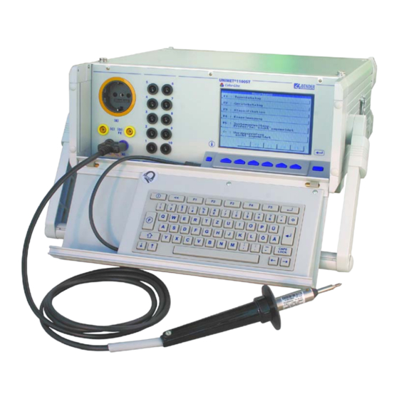
Operating manual
UNIMET® 1000ST
and UNIMET® 1100ST
Test systems for electrical safety
Power in electrical safety
TGH1256en/10.2005
Table of
Contents
Previous
Page
Next
Page
1
2
3
4
5
Advertisement
Table of Contents
Need help?
Do you have a question about the UNIMET 1000ST and is the answer not in the manual?
Ask a question
Questions and answers
Related Manuals for Bender UNIMET 1000ST
Test Equipment Bender UNIMET 1100ST Operating Manual
Test systems for electrical safety (100 pages)
Test Equipment Bender UNIMET 800ST Manual
Test system for electrical safety (100 pages)
Test Equipment Bender UNIMET 300ST Operating Manual
Testing system for electrical safety (62 pages)
Test Equipment Bender UNIMET 810ST Manual
Test system for electrical safety (100 pages)
Test Equipment Bender EDS3090 Manual
Portable equipment for insulation fault location for energised and deenergised ac and dc systems (68 pages)
Test Equipment Bender EDS440-LAF-4 Manual
Insulating fault locator to locate insulation faults in ungrounded dc, ac and three-phase power supplies (it systems) (58 pages)
Test Equipment Bender LINETRAXX MRCDB300 Series Quick Start Manual
Ac/dc sensitive residual current monitoring module for mrcd applications (8 pages)
Test Equipment Bender EDS460-DG Operating Manual
Insulation fault evaluators (76 pages)
This manual is also suitable for:
Unimet 1100st
Table of Contents
Print
Rename the bookmark
Delete bookmark?
Delete from my manuals?
Login
Sign In
OR
Sign in with Facebook
Sign in with Google
Upload manual
Upload from disk
Upload from URL


Need help?
Do you have a question about the UNIMET 1000ST and is the answer not in the manual?
Questions and answers