Table of Contents
Advertisement
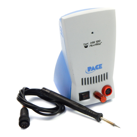
Operation and Maintenance Manual for the
HW 100 HeatWise & TW 100 TempWise Soldering
HW 100 HEATWISE
HW 100 HEATWISE
TW 100 TEMPWISE
TW 100 TEMPWISE
Systems
(5050-0512, Rev B-PRM)
Voltage
System
115 VAC
System
230 VAC
System
115 VAC
System
230 VAC
Part Number
8007-0387
8007-0388
8007-0389
8007-0390
Advertisement
Table of Contents

Related Manuals for Pace HW 100 HeatWise


Summary of Contents for Pace HW 100 HeatWise
- Page 1 Operation and Maintenance Manual for the HW 100 HeatWise & TW 100 TempWise Soldering Systems (5050-0512, Rev B-PRM) Voltage Part Number HW 100 HEATWISE System 115 VAC 8007-0387 HW 100 HEATWISE System 230 VAC 8007-0388 TW 100 TEMPWISE...
-
Page 2: Table Of Contents
System Operations Manual, Rev B Table of Contents Packing Contents .....................3 Specifications ......................3 Safety Guidelines English ......................4 French ......................4 German......................4 Italian ......................5 Portuguese ....................5 Spanish......................6 Swedish .......................6 System Set-Up ......................7 Mounting Options ..................7 Tip & Tool Stand..................7 Adjusting the Angle of the Cubby ..............7 TC 100 Handpiece Connection ..............7 System Power-Up.....................8 Tip Cartridge Installation...................8... -
Page 3: Packing Contents
System Operations Manual, Rev B Packing Contents Description HW 100 System TW 100 System Power Supply HW 100 TW 100 Handpiece TC 100 TC 100 (6010-0132-P1) (6010-0132-P1) Tip & Tool Stand 1257-0258-P1 1257-0258-P1 Power Module 5 1207-0362-01-P1 Power Module 6 1207-0362-03-P1 Power Module 7 1207-0362-05-P1... -
Page 4: Safety Guidelines
Always store the handpiece in its holder. Be sure to place the handpiece in its holder after use and allow for cooling before storing. 5. Always use PACE systems in a well ventilated area. A fume extraction system such as those available from PACE are highly recommended to help protect personnel from solder flux fumes. -
Page 5: Italian
5. Utilizzare sempre I stazioni PACE in una zona be aerata per proteggere il personale dai fumi. É fortemente raccomandato un sistema di aspirazione (dei fumi) come quello disposta dalla PACE. -
Page 6: Spanish
System Operations Manual, Rev B 5. Utilize sempre os sistemas da PACE em locais bem ventilados. Um Sistema de extracção de fumos, como os Sistemas disponiveis na PACE, são altamente recomendados para a protecção dos utilizadores contra os fumos produzidos pela solda e fluxo. -
Page 7: System Set-Up
System Operations Manual, Rev B System Set-Up Set up the HW 100 or TW 100 systems using the following steps and associated images. 1. Store the shipping container in a convenient location. Reuse of these containers will prevent damage if you store or ship your system(s). 2. -
Page 8: System Power-Up
System Operations Manual, Rev B Figure 7 2. Insert connector into power receptacle. 3. Turn the connector housing clockwise to lock in place. System Power Up 1. Insert the female end of the power cord into the AC Power Receptacle on the rear panel of the power source. 2. -
Page 9: Operation
System Operations Manual, Rev B Operation Definitions Please read and become familiar with the definitions of each of the following terms that are used repeatedly in the following operational procedures. Auto-Off: Safety feature that turns power off (10-90 minutes, settable in 10 minute increments) after the system has entered Temperature Setback. -
Page 10: Tw 100 System
System Operations Manual, Rev B 4. Once the tip has reached the desired heat level, the LED indicator will turn green and the system is ready to use. The HW 100 system comes standard with an Auto-Setback and Auto-Off Features. These are pre- programmed for 30 minute SetBack and 30 minute Auto Off, which can be turned off by the switch on the bottom of the unit. -
Page 11: Led Display
System Operations Manual, Rev B NOTE: Read the “Programming Your System” sections of this manual to utilize the full capabilities of the system. LED Display, Normal Operation The LED Display provides a 3-digit display of temperature information. The LED Display will show: 1. -
Page 12: Auto Off Mode
System Operations Manual, Rev B Exiting Temperature Setback: Listed below are 3 ways to exit Temperature Setback. 1. Press and release any key on the front panel (( ). This is the preferred method. 2. Wipe the hot handpiece tip on a wet sponge to thermally load the tip. 3. -
Page 13: Programming Your System
System Operations Manual, Rev B good linkage between tip and sensor. The System will automatically recognize that the InstaCal Module is in use and the LED Display will change to “CAL”. The calibration process will last for approximately 20 to 30 seconds. When completed, the LED Display will change to “CC”... -
Page 14: Temperature Setback
System Operations Manual, Rev B 7. The LED Display now shows the stored default High ("Hi") Temperature Limit with the display alternating to show "Hi" and the stored limit. Choose one of the following: a) Press and release the Program Key ( ) to keep the stored High Temperature Limit. -
Page 15: Exiting Programming Menu
System Operations Manual, Rev B finished, press the Program Key. ( Exiting the Programming Menu 12. The LED Display now reads "End". The Set-Up Mode procedure is now complete. Choose one of the following steps: a) Press and release the Scroll Up ( ) Key to exit Set-Up Mode and return to normal operation. -
Page 16: Tip Cartridges, Accessories & Replacement Parts
) to exit the ICA menu and resume normal operation. PACE does not recommend modifying the ICA offset to compensate for tip geometries. Please use the Cartridge OffSet (COS) value in the set-up menu to compensate for differences in tip geometries. - Page 17 System Operations Manual, Rev B PACE P/N Description 1124-0017-P1 1/16" 60 Degree Chisel 1124-0018-P1 1/32" Conical Sharp Extended 1/16" 30 Degree Chisel 1124-0019-P1 1124-0020-P1 1/8" 90 Degree Chisel 1124-0021-P1 3/128" Conical Sharp Bent 30 Degrees 1124-0022-P1 1/16" Conical Sharp 1124-0023-P1 1/8"...
- Page 18 System Operations Manual, Rev B Accessory and replacement parts for the HW 100 and TW 100 are listed below. Description PACE Part Number Tip Case – Holds 10 Tips 1310-0034-P1 (Tips not included) Tip Stand – Allows for an 1321-0639-P1 additional 10 tips to be stored on the tool stand.
-
Page 19: Corrective Maintenance
Handpiece will Defective Heater Change Tip Cartridge not heat Power Source Contact PACE Malfunction Table 3: Power Source Corrective Maintenance Applicable Regulations The HW 100 & TW 100 systems are available in either 115 VAC or 230 VAC versions, which incorporate a highly responsive, closed loop control system providing up to 55 Watts of total output www.paceworldwide.com... -
Page 20: Service & Warranty Information
Warranty service may be obtained by contacting the appropriate PACE Company or local Authorized PACE distributor as set forth below to determine if return of any item is required, or if repairs can be made by the user in the field. -
Page 21: Contact Information
System Operations Manual, Rev B PACE Incorporated retains the right to make changes to specifications contained herein at any time, without notice. Contact your local authorized PACE Distributor or PACE Incorporated to obtain the latest specifications. The following are trademarks and/or service marks of PACE, Incorporated, MD, USA: ...
Need help?
Do you have a question about the HW 100 HeatWise and is the answer not in the manual?
Questions and answers