Table of Contents
Advertisement
Advertisement
Table of Contents

Related Manuals for Bestcare BESTSTAND SA500


Summary of Contents for Bestcare BESTSTAND SA500
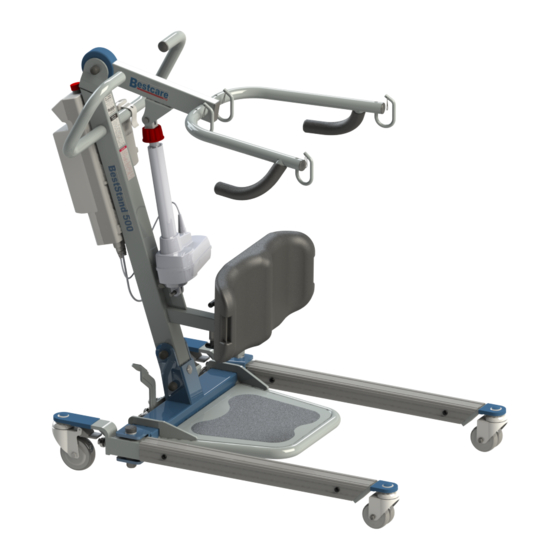
- Page 1 BESTSTAND® S I T - T O - S T A N D L I F T M o d e l : S A 4 0 0 / S A 5 0 0 SA500 model shown Ensure the product has been assembled according to the instructions in this manual.
- Page 2 Thank you for choosing Bestcare! To better serve you, please record the following information for future use: Supplier Name: ___________________________________________ Supplier Telephone: ________________________________________ Product Serial Number: _____________________________________ Date of Purchase: _________________________________________ Date of Manufacture BestStand® SA400 MAX LOAD: 400LB MASS OF LIFT:115LB(52.3KG) The manufacture date can be found on the serial number label that is located at the top of the mast.
-
Page 3: Product Description
Product Description The BestStand® SA400 and SA500 allow the patient to be lifted and transfered safely with minimal physical effort provided by the operator. The SA400 and SA500 use an electric actuator to lift patients weighing up to 400lbs and 500lbs, respectively, from a sitting to a standing position from either a bed or a chair for transferring. -
Page 4: Definitions & Symbols
DEFINITIONS & SYMBOLS n this manual the user refers to the patient or resident and may be used interchangeably at different times. Caregiver refers to the operator or person who is assisting with the transfer. Symbols used in this manual and on the product and their meanings: Warning! Failure to heed this warning may Do Not Bleach. -
Page 5: Safety Instructions
• While being lifted in a sling, always keep the user/patient centered over the base and facing the caregiver operating the lifter. • Never leave the user/patient unattended during lifting. Service personnel may contact Bestcare for any information, instructions, or certain parts for servicing purpose. - Page 6 • DO NOT replace any components of the lift without consulting with Bestcare and must follow proper instruction from Bestcare when replacing any components. • DO NOT service any parts of the lift while in use with a patient.
-
Page 7: Features And Overview
PROPRIETARY AND CONFIDENTIAL 120-400 THE INFORMATION CONTAINED IN THIS MATERIAL: DESCRIPTION: DRAWING IS THE SOLE PROPERTY OF BESTCARE LLC. ANY REPRODUCTION IN PART FINISH: SCALE: SHEET: 1 of 1 OR AS A WHOLE WITHOUT THE WRITTEN PERMISSION OF BESTCARE LLC IS PROHIBITED. - Page 8 SA400 SA500 mm (in) mm (in) 1685.7 (66.4) 1685.7 (66.4) 761.7 (30.0) 761.7 (30.0) 923.9 (36.4) 923.9 (36.4) 93.3 (3.7) 93.3 (3.7) 460.6 (18.1) 460.6 (18.1) 908.5 (35.8) 908.5 (35.8) 775.0 (30.5) 775.0 (30.5) 567.8 (22.4) 567.8 (22.4) 277.9 (10.9) 277.9 (10.9) 721.1 (28.4) 721.1 (28.4)
-
Page 9: Specifications And Options
Second Battery pack Footplate Length 14.5” 14.5” Turning Radius 54.2” 54.2” * Bestcare is committed to continuous improvements of our products therefore the specification, dimensions, and features listed above are for guidance only and are subject to change without prior notice. -
Page 10: Installation
Installation Step 1: Remove the base from box. Step 2: Remove all the plastic caps, then all the bolts, nuts, and washers on the base bracket. Step 3: Insert the mast and align the upper hole on the mast with the upper hole on the bracket. - Page 11 Step 4: Other two holes should be aligned, align the holes if needed. Reinsert and tighten the bolts using the EZ Tools as follows. Step 5: Remove the plastic caps, then all the bolt, nut and washers on the boom. Tighten the bolt and nut using the EZ Tools as follows Step 6: Secure the boom to the mast using the bolt, nut and washer.
- Page 12 Step 7: Secure the lower end of the actuator to the mast bracket using a pin and retaining ring as shown Step 8: Secure the upper end of the actuator to the boom bracket using a pin and retaining ring as shown. Step 9: Attach the footplate to the base using the two hooks by lowering it onto the top surface of the base.
- Page 13 Step 10: Attach the included plastic washer to the kneepad frame as shown in the picture below, and place them in between the kneepad bracket. Secure the parts with the bolt, nut and washers using EZ Tools. Step 11: Insert the kneepad frame into the tube located on the mast. Pull the pin that is below the tube, then insert the tube of the kneepad, and release the handle to secure the kneepad in place.
- Page 14 Step 6: Power Control Unit M5 SCREWS M4 SCREWS 2920 PACIFIC DRIVE UNLESS OTHERWISE SPECIFIED: NORCROSS, GA 30071 ALL DIMENSIONS IN MM DRAWN BY: DATE:...
- Page 15 Operating Instructions Double check all assemblies for tightness and read operating instructions carefully prior to use. For optimum performance the lift should be transported and stored in following condition range: • -25°C to +5°C (-13°F to 41°F), and • +5°C to +35°C (41°F to 95°F) at a non-condensing relative humidity 0% to 90% •...
- Page 16 Power Control Unit Overview Emergency Stop Button Up / Down Button Battery Pack Release Handle LCD Display Panel Battery Pack Charger DC In Not Used Additional Battery Pack (Optional) Charging Cradle Actuator (Optional) Hand Control 1. Connect Actuator as shown above. 2.
- Page 17 Release Pressed in LCD Display Panel Signs When the emergency stop button is released, the LCD Display Panel will show one of the four signs below. • The sign will display for 5 seconds. • Then the lift will go into standby mode and the sign disappears. •...
- Page 18 Operating Lift: Using Hand Control LED Indicator Lifting * Green = In Use * Blank = Standby Lowering Operating Lift: Using LCD Display Panel...
- Page 19 Warning! - Battery Low and Charging is Needed If the battery needs to be charged, the LCD Display Panel will show a blinking low battery sign shown on the left either when the emergency stop button is released or when a button on the LCD Display Panel is pressed.
- Page 20 Available slings compatible with Stand Assist Lift Stand Assist Sling Sling Model Sling Size SL-SA662 SL-SA663 SL-SA664 Stand Assist Buttock Strap Sling Model Strap Size SL-SA669 Standard SL-SA669B Bariatric Sling Model Sling Description Knee Belt WP-SA400E-KB Stand Assist Toileting Sling Sling Model Sling Size SL-TP331...
- Page 21 FITTING STAND ASSIST SLING Attach the shoulder straps to the hooks. Shoulder Strap Loop Shoulder Strap Red Pad Black Strap Waist Belt Belt Buckle Sling Loop Options LONG LOOP LONG LOOP - reclined position CENTER LOOP CENTER LOOP - semi reclined SHORT LOOP SHORT LOOP - most upright 1.
- Page 22 FITTING STAND ASSIST BUTTOCK STRAP DIAGRAM 1 1. Check sling weight capacity for the patient being lifted. Do not exceed maximum safe working load. 2. Review following procedures carefully prior to attempting lift. Call with any questions. 3. Position the sling around the buttocks of the patient. This sling is designed to support the middle and lower part of the body.
- Page 23 LIFT AND TRANSFER FROM BED 1. Fit sling as described in “Fitting Stand Assist Sling”. 2. Push lift towards patient. Open the base of the lift. 3. Position patient’s feet on the footplate and knees against the knee pad. 4. Attached the sling straps to the hooks. 5.
- Page 24 LIFT AND TRANSFER FROM COMMODE BESTCARE TOILETING SLING The Bestcare Toileting Sling is be used with the BestStand® to lift up a patient in a sitting position; it is not meant for the patient to be standing! The Toileting Sling supports the client...
-
Page 25: Maintenance And Inspection
• With proper use and care, the expected lifetime of the lift is 10 years or 20,000 cycles. • The expected lifetime of the electrical components are 3 years. • Contact Bestcare for recycling information First Received Monthly Every 3 Months Boom &... - Page 26 • REPLACE a sling when it show signs of deterioration. Deterioration of sling • Contact Bestcare for “Guideline for Identifying Deteriorated Slings” if needed. Disinfecting of the lift and sling • Inspect slings prior to each use for contamination from previous use.
-
Page 27: Troubleshooting Guide
Troubleshooting Guide The following list of encountered problems and solutions will assist you in determining what may be causing your patient lift not to function as designed. If you have a problem occurring which is not listed below please contact your dealer or technical support for help. Do not attempt to repair or replace components or parts on your lift as this may void your warranty or cause further problems that may result in patient injury. - Page 28 Emergency Lowering Mechanism Contact your dealer immediately if standard troubleshooting techniques do not correct the failure. Do not attempt to lift until all failure and safety issues have been resolved. In case of lift failure, please follow the procedures below to safely lower the user. The Emergency Lowering Device is located at the top of the actuator shaft.
-
Page 29: Warranty Policy
RETURN GOODS POLICY Patient lifts may not be returned unless the wrong lift is shipped in error by Bestcare or the lift is heavily damaged or defective out of the box. For all other items, purchaser may request a RA for purchased goods within thirty (30) days of purchase invoice date. All returns must be received by Bestcare no later than thirty (30) days after authorization or the RA will be voided. - Page 30 Notes...
- Page 31 Notes...
- Page 32 Bestcare LLC 2920 Pacific Drive Norcross, GA 30071 Ver 2020.02 www.bestcarellc.com | © 2019 Bestcare LLC...
Need help?
Do you have a question about the BESTSTAND SA500 and is the answer not in the manual?
Questions and answers