Advertisement
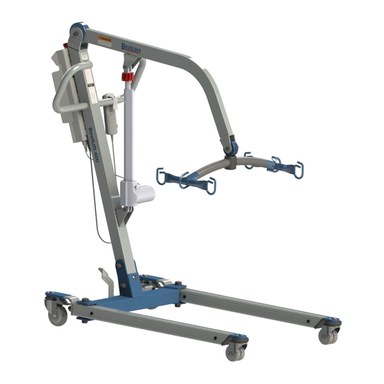
BESTLIFT
F U L L B O D Y P A T I E N T L I F T
BestLift 400 series
MODELS
BestLift 500 series
BestLift 600 series
Ensure the product has been assembled according to the
instructions in this manual.
All operators should have received or read and understood the
instructions for safe and proper operation of the patient lift.
L.L.C.
Advertisement
Table of Contents

Related Manuals for Bestcare BestLift 400 Series


Summary of Contents for Bestcare BestLift 400 Series
- Page 1 BESTLIFT F U L L B O D Y P A T I E N T L I F T L.L.C. BestLift 400 series MODELS BestLift 500 series BestLift 600 series Ensure the product has been assembled according to the instructions in this manual.
- Page 3 Date of Purchase: INSPECT YOUR MERCHANDISE Upon receipt of your Bestcare Lift, verify that all merchandise is complete and free from any shipping damage. Refuse delivery if the packaging appears to be badly damaged. If the merchandise is received damaged or is missing components, contact the shipping...
-
Page 4: Safety Instructions
SAFETY INSTRUCTIONS mechanical equipment requires. Please pay careful attention to the following important information regarding the care, maintenance, and operation of the patient lift. Carefully read these instructions before PLEASE NOTE THE FOLLOWING: Special care must be taken with users/patients who cannot themselves provide assistance while being lifted. - Page 5 DEFINITIONS & SYMBOLS In this manual the user refers to the patient or resident and may be used interchangeably at different times. Caregiver refers to the operator or person who is assisting with the transfer. Symbols used in this manual and their meanings: Warning! Failure to heed this warning may result in damage to the product or serious injury to the operator and/or user.
-
Page 6: Product Features
PRODUCT FEATURES DESCRIPTION & APPLICATIONS Designed to provide the perfect combination of patient safety, weight capacity and maneuverability. This lift is manufactured to meet the needs of the general patient population in hospitals and nursing homes. Caregivers appreciate the ease of operation and patients are reassured by the stability and overall comfort provided. -
Page 7: Specifications
Optional 6 Point Spreader Bar Emergency Release Weigh Scale Optional Optional Optional *Bestcare is committed to continuous improvements of our products therefore the specs, dimensions, and features listed above are for guidance only and subject to change without prior notice. - Page 8 ASSEMBLY Prior to assembly, unpack all parts from the shipping carton and check for any missing parts. Contact you dealer immediately if a part is missing. Parts List for PL400 SERIES Boom Mast Base Spreader bar w/ Sling hooks Pendant / Hand Control Actuator Control box and Battery Pack Rear Caster w/ Brake...
- Page 9 Parts List for PL600 SERIES Boom Mast Base Spreader bar w/ Sling hooks Pendant / Hand Control Actuator Control box and Battery Pack Rear Caster w/ Brake Front dual casters STEP BY STEP ASSEMBLY Engage the brakes. Remove the bolts from the bottom of the mast and base.
- Page 10 SPREADER BAR ASSEMBLY FOR PL400 & PL600 SERIES Attach the spreader bar to the boom and insert pin. Insert keeper ring to secure spreader bar to boom. SPREADER BAR ASSEMBLY FOR PL500 SERIES Attach the spreader bar to the boom and insert pin.
- Page 11 ACTUATOR ASSEMBLY FOR PL400E B. Attach the top of the actuator to A. Attach the bottom of actuator to the bracket on the boom and insert the bracket on the mast and insert pin. Insert keeper ring through hole pin. Insert keeper ring through hole in pin to secure actuator to upper in pin to secure base of actuator bracket.
-
Page 12: Battery Installation
BATTERY INSTALLATION FOR PERFORMANCE SERIES (for LEGACY electronics assembly see page 16) Install the control box. Slide the control box over and onto the metal tab mounted at the bottom of the Mast. Line up the control box with the hole at the top of the mast and insert the screw to hold the control box in place. -
Page 13: Lcd Indicators
FEATURES: Smart charging function for longer battery life Battery capacity indicator on battery pack Soft start and stop for lifting actuator Soft and Hardware over-current protection Actuator’s Over-duty protection with sign on LCD Emergency stop button interrupts the power supply to the actuator and makes the actuator stop immediately in case of sudden danger Internal charger... - Page 14 EMERGENCY STOP FOR PERFORMANCE ELECTRONICS ONLY Emergency stop button interrupts the power supply to the actuators and makes the actuators stop immediately in case of sudden danger. press RED button turn RED button clockwise LOCKED UNLOCKED NOT BE USED FOR OVER 3 DAYS TO MAINTAIN OPTIMAL BATTERY LIFE AND PERFORMANCE. FEATURES OF POWER PLUG: C-CLAMP : the power plug...
- Page 15 (extra wall-mount charger and battery pack) AC on LED (green) Charge on LED Battery pack release (yellow) Battery indicator AC Power Plug Step 1: Install two mounting bolts (M5 or gauge 10 having at least 8mm head) onto the mounting surface that are 12.4 in. / 31.6cm apart as shown in Fig. A. Step 2: Turn the lock mechanism to the unlocked position Fig.B.
-
Page 16: Checking The Battery
(for PERFORMANCE electronic assembly see page 12) Attach the Control Box Hanging Bracket to the Mast and tighten the nuts. Once the bracket is secure, then place the Legacy Electronic Box inside. * refer to page 15 for charging instructions Emergency button Battery indicator Battery Test Button... -
Page 17: Charging The Battery
CHARGING THE BATTERY Ensure the power is switched “ON” (the red “RESET” button should be up). Insert charging plug into charging port on the control box. Plug charger to power supply. All lights of battery indicator should be “ON” while charging. It takes approximately 2-3 hours to fully charge the batteries from one green light. -
Page 18: Operating Instructions
OPERATING INSTRUCTIONS Double check all assemblies for tightness and read operating instructions carefully prior to use. Do not attempt to use patient lift unless the patient exhibits control over the upper body, strength to grasp the handles, ability to bear some weight and Turn on the power by twisting the RED RESET BUTTON clockwise. - Page 19 Turn the lift “ON” by turning the red “RESET” button clockwise. Turn the lift “OFF” by pressing down the “RESET” button. TRANSFER FROM BED User/patient should be in the center of the bed. Position user onto his/her side by rolling user towards you. Roll the sling in half, approximately.
- Page 20 Attach Loop A and D of the sling to Hook A on Spreader Bar; attach Loop B and C to Hook B. Lift the user above the bed by using the hand control. Pull lift away from bed. Position user over the wheelchair or chair then lower the patient onto the surface.
-
Page 21: Maintenance And Inspection
MAINTENANCE & INSPECTION The operator of the lift shall inspect the BestLift before each use. Check all bolts for tightness. Make sure the base can be easily widened, and that all lift parts are in place. Make sure that casters can be turned freely, and that caster brakes can be engaged. - Page 22 FIRST EVERY 3 RECEIVED BASE & FOOT PEDAL Apply grease to caster ball bearings if needed. Check welding joints for rust and crack. AS NEEDED ACTUATOR & CONTROL BOX to the mast. Make sure the actuator is secured to the boom and mast with pins and key rings Make sure actuator plug into control box is not loose.
-
Page 23: Troubleshooting Guide
TROUBLESHOOTING GUIDE The following list of encountered problems and solutions will assist you in determining what may be causing your patient lift not to function as designed. If you have a problem occurring which is not listed below please contact your dealer or technical support for help. Do not attempt to repair or replace components or parts on your lift as this may void your warranty or cause further problems that may result in patient injury. - Page 24 In case there is a failure with the actuator or electronics and the user is left suspended in mid-air, please follow the procedures below to safely lower the user to a safer position. Contact your dealer immediately if standard troubleshooting techniques do not correct the failure.
- Page 25 PL500-series Turn clockwise to lower PL600-series Turn clockwise to lower NOTE: THE EMERGENCY LOWERING DEVICE IS INTENDED FOR USE DURING LIFT FAILURE. THIS DEVICE WILL ALLOW LOWERING OF PATIENTS ONLY. PLEASE CONTACT YOUR DEALER IMMEDIATELY IN CASE OF FAILURE.
- Page 26 NOTES...
- Page 27 RA number or the shipment will not be received or any credit issued. When a part is returned to Bestcare LLC for warranty inspection a $50 service charge will apply if the part is not defective.
- Page 28 L.L.C. Bestcare LLC , GA 300 tel. 678-679-6690 free 1-877-822-9033 www.bestcarellc.com | © 2013 Bestcare LLC...
Need help?
Do you have a question about the BestLift 400 Series and is the answer not in the manual?
Questions and answers