Table of Contents
Advertisement
Quick Links
Advertisement
Table of Contents

Related Manuals for Supero C9Z390-CG


Summary of Contents for Supero C9Z390-CG
- Page 1 C9Z390-CG/CGW USER’S MANUAL Revision 1.0...
- Page 2 The information in this User’s Manual has been carefully reviewed and is believed to be accurate. The vendor assumes no responsibility for any inaccuracies that may be contained in this document, makes no commitment to update or to keep current the information in this manual, or to notify any person or organization of the updates.
- Page 3 This manual is written for system integrators, PC technicians, and knowledgeable PC users. It provides information for the installation and use of the C9Z390-CG/CGW motherboard. Manual Organization Chapter 1 describes the features, specifications and performance of the motherboard, and provides detailed information on the Intel® Z390 chipset.
- Page 4 Supermicro C9Z390-CG/CGW Motherboard User’s Manual Checklist Congratulations on purchasing your computer motherboard from an ac- knowledged leader in the industry. Supermicro boards are designed with the utmost attention to detail to provide you with the highest standards in quality and performance.
- Page 5 Standardized Warning Statements Standardized Warning Statements The following statements are industry-standard warnings, provided to warn the user of situations which have the potential for bodily injury. Should you have questions or experience difficulty, contact Supermicro's Technical Support department for assistance. Only certified technicians should attempt to install or configure components.
- Page 6 Supermicro C9Z390-CG/CGW Motherboard User’s Manual ¡Advertencia! Existe peligro de explosión si la batería se reemplaza de manera incor- recta. Reemplazar la batería exclusivamente con el mismo tipo o el equivalente recomendado por el fabricante. Desechar las baterías gasta- das según las instrucciones del fabricante.
- Page 7 Standardized Warning Statements 製品の廃棄 この製品を廃棄処分する場合、 国の関係する全ての法律 ・ 条例に従い処理する必要が あります。 警告 本产品的废弃处理应根据所有国家的法律和规章进行。 警告 本產品的廢棄處理應根據所有國家的法律和規章進行。 Warnung Die Entsorgung dieses Produkts sollte gemäß allen Bestimmungen und Gesetzen des Landes erfolgen. ¡Advertencia! Al deshacerse por completo de este producto debe seguir todas las leyes y reglamentos nacionales.
- Page 8 Supermicro C9Z390-CG/CGW Motherboard User’s Manual Contacting Supermicro Headquarters Address: Super Micro Computer, Inc. 980 Rock Ave. San Jose, CA 95131 U.S.A. Tel: +1 (408) 503-8000 Fax: +1 (408) 503-8008 Email: marketing@supermicro.com (General Information) support@supermicro.com (Technical Support) Website: www.supermicro.com Europe Address: Super Micro Computer B.V.
- Page 9 Contacting Supermicro Where to Find More Information For your system to work properly, please follow the links below to download all necessary drivers/utilities and the user's manual for your motherboard. Supermicro product manuals: http://www.supermicro.com/support/ manuals/ Product Drivers and utilities: https://www.supermicro.com/wftp/driver/ If you have any questions, please contact our support team at support@ supermicro.com.
-
Page 10: Table Of Contents
Supermicro C9Z390-CG/CGW Motherboard User’s Manual Table of Contents Preface Chapter 1 Introduction Overview ................1-1 Chipset Overview ..............1-1 Motherboard Features ............1-2 Special Features ..............1-5 PC Health Monitoring .............. 1-5 ACPI Features ............... 1-6 Power Supply ................ 1-7 Super I/O ................ - Page 11 Table of Contents H/W Monitor ............... 4-48 Save & Exit ................. 4-50 BIOS Update ............... 4-52 Appendix A BIOS Error Beep Codes BIOS Error Beep Codes ............A-1 Appendix B Software Installation Instructions Installing Drivers ..............B-1 Configuring SuperDoctor ® 5 ........... B-2 Appendix C UEFI BIOS Recovery Instructions An Overview to the UEFI BIOS ..........
- Page 12 Supermicro C9Z390-CG/CGW Motherboard User’s Manual Notes...
-
Page 13: Chapter 1 Introduction
The C9Z390-CG/CGW motherboard supports an 8th/9th Gen Intel® Core i9/i7/i5/i3/Pentium®/Celeron® processor in an LGA1151 socket. With the Intel Z390 chipset built in, the C9Z390-CG/CGW motherboard offers substantial system performance and storage capability in a sleek package. Please refer to our website (http://www.supermicro.com/prod-... -
Page 14: Motherboard Features
Supermicro C9Z390-CG/CGW Motherboard User’s Manual 1-3 Motherboard Features Single 8th/9th Generation Intel Core™ i9/i7/i5/i3 Pentium/Celeron processor in an LGA1151 H4 type socket Supports up to 128GB (available only for selected 9th Memory Gen processors) of unbuffered, non-ECC, DDR4 memory with speeds of up to 3733+ MHz (OC) - Page 15 Hard Drive Connections SATA 3.0 (6Gb/s) Six (6) SATA0-5 via Intel Z390 USB Devices C9Z390-CG/CGW One (1) USB 3.1 Gen 2 Type C port on the I/O back panel Three (3) USB 3.1 Gen 2 Type A ports on the I/O back panel One (1) front accessible USB 3.1 Gen 2 port...
- Page 16 Supermicro C9Z390-CG/CGW Motherboard User’s Manual PECI (Platform Environment Configuration Interface) System 2.0 support Management System resource alert via SuperDoctor® 5 SuperDoctor 5, NMI Chassis Intrusion header and detection Watch Dog Timer BIOS flash upgrade utility CD Utilities Drivers and software for Intel Z390 chipset utilities...
-
Page 17: Special Features
Chapter 1: Introduction 1-4 Special Features Recovery from AC Power Loss Basic I/O System (BIOS) provides a setting for you to determine how the system will respond when AC power is lost and then restored to the system. You can choose for the system to remain powered off, (in which case you must press the power switch to turn it back on), or for it to automatically return to a power-on state. -
Page 18: Acpi Features
Supermicro C9Z390-CG/CGW Motherboard User’s Manual System Resource Alert This feature is available when the system is used with SuperDoctor 5 in the Windows and Linux operating systems. SuperDoctor is used to notify the user of certain system events. For example, you can also... -
Page 19: Power Supply
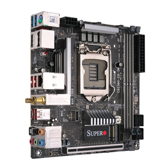
Chapter 1: Introduction 1-7 Power Supply As with all computer products, a stable power source is necessary for proper and reliable operation. It is even more important for processors that have high CPU clock rates or overclocked processors. This motherboard accommodates a 24-pin ATX power supplies. Although most power supplies generally meet the specifications required by the CPU, some are inadequate. - Page 20 Supermicro C9Z390-CG/CGW Motherboard User’s Manual C9Z390-CG/CGW Motherboard Image Note: All graphics shown in this manual were based upon the latest PCB Revision available at the time of publishing of the manual. The motherboard you've received may or may not look exactly the same...
- Page 21 Chapter 1: Introduction C9Z390-CG/CGW Motherboard Layout JUSBLAN2 AUDIO FP LAN CTRL DP1/DP2 HD AUDIO KB/MOUSE USB 2/3 (3.0) JSPDIF_OUT (For C9Z390-CGW only) HDMI LAN2 USB 4/5 (3.1) MH12 USB 6/7(3.1) LAN1 JRLED1 22110 WIFI+BT (For C9Z390-CGW only) MH11 2280 J9702...
- Page 22 Supermicro C9Z390-CG/CGW Motherboard User’s Manual C9Z390-CG/CGW Block Diagram PCI-E x16 SLOT6 PCI-E 3.0 x8 PCI-E 3.0 x16 SVID IMVP8/9 IMVP8/9 8.0 GT/s 8.0 GT/s PCI-E x8 (IN x16) SLOT6 PCI-E x8 (IN x16) SLOT3 PCI-E 3.0 x4 INTEL LGA1151 PCI-E x4 (IN x16) SLOT3 8.0 GT/s...
- Page 23 Chapter 1: Introduction C9Z390-CG/CGW Quick Reference JUSBLAN2 AUDIO FP LAN CTRL DP1/DP2 HD AUDIO KB/MOUSE USB 2/3 (3.0) JSPDIF_OUT (For C9Z390-CGW only) HDMI LAN2 USB 4/5 (3.1) MH12 USB 6/7(3.1) LAN1 JRLED1 22110 WIFI+BT (For C9Z390-CGW only) MH11 2280 J9702...
- Page 24 Supermicro C9Z390-CG/CGW Motherboard User’s Manual Connector Description 12V_PUMP_PWR1 12V power connector for CPU pump of liquid cooling AUDIO FP Front Panel Audio Header Onboard Battery COM1 COM1 Header CPU_FAN1/FAN2 CPU Fan Headers CPU SLOT1 PCI-E 3.0 x4 PCI-Express x4 Slot (PCI-E 3.0 x4 link) CPU SLOT3 PCI-E 3.0 x8...
- Page 25 Chapter 1: Introduction Connector Description KB/ MOUSE PS/2 Keyboard/Mouse Port LAN1 RJ45 GbE LAN Port LAN2 RJ45 10GbE LAN Port PCI-E M.2-E1 M.2 E-key Connector (Pre-installed Intel Wireless-AC 9560 WIFI module) PCI-E M.2-M1/M.2-M2 PCI-E M.2 Connectors (Small form factor devices and other portable devices for high speed NVMe SSDs) SYS_FAN1/FAN2/FAN3 System Fan Headers...
- Page 26 Supermicro C9Z390-CG/CGW Motherboard User’s Manual Notes 1-14...
-
Page 27: Chapter 2 Installation
Chapter 2: Installation Chapter 2 Installation 2-1 Installation Components and Tools Needed Screws Phillips-Head Screwdriver Intel ® LGA 1151 Processor DDR4 DIMMs PC Chassis Heatsink with Fan Power Supply Video Card (Optional) SATA/USB Optical Drive (Optional) SATA Hard Disk Drive... -
Page 28: Static-Sensitive Devices
Supermicro C9Z390-CG/CGW Motherboard User’s Manual 2-2 Static-Sensitive Devices Electrostatic-Discharge (ESD) can damage electronic components. To avoid damaging your system board, it is important to handle it very carefully. The following measures are generally sufficient to protect your equipment from ESD. -
Page 29: Processor And Heatsink Installation
Chapter 2: Installation 2-3 Processor and Heatsink Installation Attention! When handling the processor package, avoid placing direct pressure on the label area of the fan. Important: • Always connect the power cord last, and always remove it before adding, removing, or changing any hardware components. Make sure that you install the processor into the CPU socket before you install the CPU heatsink. - Page 30 Supermicro C9Z390-CG/CGW Motherboard User’s Manual 2. Gently lift the load lever to open the load plate. Remove the plastic cap. 3. Use your thumb and your index finger to hold the CPU at the North center edge and the South center edge of the CPU.
- Page 31 Chapter 2: Installation 5. Do not rub the CPU against the surface or against any pins of the socket to avoid damaging the CPU or the socket. 6. With the CPU inside the socket, inspect the four corners of the CPU to make sure that the CPU is properly installed.
- Page 32 Supermicro C9Z390-CG/CGW Motherboard User’s Manual Installing a CPU Heatsink 1. Apply the proper amount of thermal grease to the heatsink. 2. Place the heatsink on top of the CPU so that the four mount- ing holes on the heatsink are aligned with those on the retention mechanism.
- Page 33 Chapter 2: Installation Removing a Heatsink Warning: We do not recommend that the CPU or the heatsink be removed. However, if you do need to remove the heatsink, please follow the instruc- tions below to uninstall the heatsink to avoid damaging the CPU or other components.
-
Page 34: Installing Ddr4 Memory
Supermicro C9Z390-CG/CGW Motherboard User’s Manual 2-4 Installing DDR4 Memory Note: Check the Supermicro website for recommended memory modules. Attention! Exercise extreme care when installing or removing DIMM modules to prevent any possible damage. DIMM Installation JUSBLAN2 AUDIO FP LAN CTRL... - Page 35 DIMMA2 DIMMA1 Towards the CPU The C9Z390-CG/CGW supports up to 128GB (available only for selected 9th Gen processors) of Unbuffered (UDIMM) non-ECC DDR4 memory with speeds of up to 3733+MHz (OC) in four 288-pin memory slots. Populating these DIMM modules with a pair of memory modules of the same type and size will result in interleaved memory, which will improve memory performance.
- Page 36 Supermicro C9Z390-CG/CGW Motherboard User’s Manual Memory Population Guidelines When installing memory modules, the DIMM slots should be populated in the following order: DIMMA2, DIMMB2, then DIMMA1, DIMMB1. • Always use DDR4 DIMM modules of the same size, type, and speed.
-
Page 37: Motherboard Installation
Chapter 2: Installation 2-5 Motherboard Installation All motherboards have standard mounting holes to fit different types of chassis. Make sure that the locations of all the mounting holes for both motherboard and chassis match. Although a chassis may have both plas- tic and metal mounting fasteners, metal ones are highly recommended because they ground the motherboard to the chassis. - Page 38 Supermicro C9Z390-CG/CGW Motherboard User’s Manual Installing the Motherboard 1. Install the I/O shield into the back of the chassis. 2. Locate the mounting holes on the motherboard. (See the previous page.) 3. Locate the matching mounting holes on the chassis. Align the mounting holes on the motherboard against the mounting holes on the chassis.
-
Page 39: Installation (Optional)
Chapter 2: Installation 2-6 M.2 Installation (optional) Two M.2 (M-key) connectors are supported by the C9Z390-CG/CGW. M.2 devices are used for solid state storage and internal expansion. Follow the steps below in order to install an M.2 device. 1) Locate one of two standoffs. -
Page 40: Connectors/Io Ports
Supermicro C9Z390-CG/CGW Motherboard User’s Manual 2-7 Connectors/IO Ports The I/O ports are color coded in conformance with the industry standards. See the figure below for the colors and locations of the various I/O ports. I/O Back Panel JUSBLAN2 AUDIO FP... - Page 41 SuperSpeed Transmitter F. USB 7 StdA_SSTX+ Differential Pair GND_DRAIN Ground for Signal G. USB 0/1 Return H. USB 8/9 USB 2.0 Differential Pair C9Z390-CG/CGW JUSBLAN2 AUDIO FP LAN CTRL DP1/DP2 HD AUDIO KB/MOUSE JSPDIF_OUT USB 2/3 (3.0) (For C9Z390-CGW only) LAN2 USB 4/5 (3.1)
- Page 42 Supermicro C9Z390-CG/CGW Motherboard User’s Manual Front Panel USB 10 (3.1 Gen 2) Pin Definitions Pin# Definition Pin# Definition Pin# Definition VBUS RX2+ TX1+ SBU1 RX2- TX1- SBU2 VBUS RX1+ TX2+ RX1- TX2- VBUS A. USB 10 JUSBLAN2 AUDIO FP LAN CTRL...
- Page 43 LED (Yellow, +3V3SB) TD2+ Ground TD2- Ground TD3+ Ground TD3- Ground ATX PS/2 Keyboard/Mouse Port The ATX PS/2 keyboard and mouse port is located on the back panel above USB 2/3. A. PS/2 Keyboard/Mouse Port B. LAN1 C. LAN2 C9Z390-CG/CGW 2-17...
- Page 44 Supermicro C9Z390-CG/CGW Motherboard User’s Manual HD AUDIO Ports This motherboard features a 7.1+2 Channel High Definition Audio (HDA) codec that provides 10 DAC channels. The HD Audio connections on the I/O back panel simultaneously supports multiple-streaming 7.1 sound playback with two channels of independent stereo output through the front panel stereo out for front, rear, center and subwoofer speakers.
- Page 45 Chapter 2: Installation Front Control Panel JF1 contains header pins for various buttons and indicators that are normally located on a control panel at the front of the chassis. These connectors are designed specifically to use with Supermicro chassis. See the figure below for the descriptions of the front control panel buttons and LED indicators.
- Page 46 Supermicro C9Z390-CG/CGW Motherboard User’s Manual Front Control Panel Pin Definitions POWER LED POWER LED Pin Definitions (JF1) The Power LED connection is located on Pin# Definition pins 15 and 16 of JF1. Refer to the table PWR LED (+) on the right for pin definitions.
- Page 47 Chapter 2: Installation Overheat (OH)/Fan Fail LED OH/Fan Fail LED Pin Definitions (JF1) Connect an LED cable to OH/Fan Fail Pin# Definition connections on pins 7 and 8 of JF1 to provide warnings for chassis overheat/ OH/Fan Fail LED fan failure. Refer to the tables on the right for more information.
- Page 48 Supermicro C9Z390-CG/CGW Motherboard User’s Manual Power Button Power Button Pin Definitions (JF1) The Power Button connection is located on pins 1 and 2 of JF1. Momentarily Pin# Definition contacting both pins will power on/off Signal the system. This button can also be con-...
-
Page 49: Connecting Cables
Chapter 2: Installation 2-8 Connecting Cables This section provides brief descriptions and pin-out definitions for on- board headers and connectors. Be sure to use the correct cable for each header or connector. ATX Main PWR and CPU PWR ATX Power 24-pin Connector Connectors Pin Definitions Pin#... - Page 50 Refer to the table on the right for pin definitions. Pump Power Header The C9Z390-CG/CGW has one +12V header for optional CPU liquid cool- ing systems. When using a liquid cooling system, attach the pump power cable to the PUMP_PWR1 header.
- Page 51 Chapter 2: Installation Speaker Header Speaker Header Pin Definitions On the JD1 header, pins 3 and 4 are Pin Setting Definition used for a buzzer. If you wish to use an Pins 3-4 Buzzer external speaker, close pins 1-4 with a Pins 1-4 External Speaker cable.
- Page 52 Supermicro C9Z390-CG/CGW Motherboard User’s Manual Serial (COM) Header Serial (COM ) Header Pin Definitions There is one serial (COM) header on Pin# Definition Pin# Definition the motherboard. Refer to the table on the right for pin definitions. Ground Power SMB (I2C) Headers...
- Page 53 Chapter 2: Installation DOM PWR Connector DOM PWR Connector Pin Definitions The Disk-On-Module (DOM) power con- Pin# Definition nector, located at JSD1, provides 5V power to a solid state DOM storage Ground device connected to one of the SATA ports. Refer to the table on the right for Ground pin definitions.
- Page 54 Supermicro C9Z390-CG/CGW Motherboard User’s Manual M.2 Connectors M.2 is formerly known as Next Generation Form Factor (NGFF). The three M.2 connectors are designed for internal mounting de- vices. The M.2 M-Key 2242/2280/22110 (PCI-E M.2-M1) and 2260/2280/22110 (PCI-E M.2-M2) provide native PCI-E SSD sup- port.
- Page 55 Chapter 2: Installation Front Panel Audio Header 10-pin Audio Header Pin Definitions A 10-pin Audio header at AUDIO FP is Pin# Signal supported on the motherboard. This Microphone_Left header allows you to connect the moth- Audio_Ground erboard to a front panel audio control Microphone_Right panel, if needed.
-
Page 56: Jumper Settings
Supermicro C9Z390-CG/CGW Motherboard User’s Manual 2-9 Jumper Settings Explanation of Jumpers To modify the operation of the motherboard, jumpers can be used to choose between optional settings. Jumpers create shorts between two pins to change the function of the connector. Pin 1 is identified with a square solder pad on the printed circuit board. - Page 57 Chapter 2: Installation CLEAR CMOS CLEAR CMOS is used to clear the saved system setup configuration stored in the CMOS chip. Pressing this button will erase all user settings and revert everything to their factory defaults. Watch Dog Watch Dog Jumper Settings Watch Dog (JWD1) is a system monitor Pin#...
- Page 58 Supermicro C9Z390-CG/CGW Motherboard User’s Manual Manufacturing Mode Close pins 2 and 3 of Jumper JPME2 Manufacturing Mode Jumper Settings to bypass SPI flash security and force Pin# Definition the system to operate in Manufacturing Normal (Default) Mode, allowing the user to flash the sys-...
-
Page 59: Onboard Indicators
Chapter 2: Installation 2-10 Onboard Indicators LAN LEDs 1G/10G LAN Activity Indicator Two LAN ports are on the I/O back panel. LED Settings Both Ethernet LAN ports have two LEDs Color Status Definition (Light Emitting Diode). The yellow LED Yellow Flashing Active indicates activity, while the Link LED... - Page 60 JSTBY1 Supermicro C9Z390-CG/CGW Motherboard User’s Manual LED7201 Status Display LED1 LED4 is made up of two alpha- numeric displays that will display a status or POST code, when the motherboard is powered on. Please download the following AMI publication for a complete list of POST codes: https://ami.com/ami_downloads/Aptio_V_Status_Codes.pdf...
-
Page 61: Hard Drive Connections
Chapter 2: Installation 2-11 Hard Drive Connections SATA Connections SATA 3.0 Connectors Pin Definitions Six Serial ATA (SATA) 3.0 connectors Pin# Signal (I-SATA0~5) are supported by the Ground Intel Z390 chip. Refer to the table on the SATA_TXP right for pin definitions. SATA_TXN Ground SATA_RXN... - Page 62 Supermicro C9Z390-CG/CGW Motherboard User’s Manual Notes 2-36...
-
Page 63: Chapter 3 Troubleshooting
Chapter 3: Troubleshooting Chapter 3 Troubleshooting 3-1 Troubleshooting Procedures Use the following procedures to troubleshoot your system. If you have followed all of the procedures below and still need assistance, refer to the ‘Technical Support Procedures’ and/or ‘Returning Merchandise for Service’ section(s) in this chapter. - Page 64 Supermicro C9Z390-CG/CGW Motherboard User’s Manual 5. The battery on your motherboard may be old. Check to make sure that it still supplies ~3VDC. If it does not, replace it with a new one. No Video 1. If the power is on, but you have no video--in this case, you will need to remove all the add-on cards and cables first.
-
Page 65: Technical Support Procedures
Chapter 3: Troubleshooting 3. If the above steps do not fix the Setup Configuration problem, contact your vendor for repairs. 3-2 Technical Support Procedures Before contacting Technical Support, please make sure that you have followed all the steps listed below. Also, note that as a motherboard manufacturer, Supermicro does not sell directly to end users, so it is best to first check with your distributor or reseller for troubleshooting services. -
Page 66: Frequently Asked Questions
Supermicro C9Z390-CG/CGW Motherboard User’s Manual 3-3 Frequently Asked Questions Question: What type of memory does my motherboard support? Answer: The C9Z390-CG/CGW supports up to 128GB (available only for selected 9th Gen processors) of unbuffered Non-ECC DDR4. See Section 2-4 for details on installing memory. -
Page 67: Battery Removal And Installation
Chapter 3: Troubleshooting Question: I think my BIOS is corrupted. How can I recover my BIOS? Answer: Please see Appendix C - BIOS Recovery for detailed instructions. 3-4 Battery Removal and Installation Battery Removal To remove the onboard battery, follow the steps below: 1. -
Page 68: Returning Motherboard For Service
Supermicro C9Z390-CG/CGW Motherboard User’s Manual Battery Installation 1. To install an onboard battery, follow the steps 1 and 2 above and continue below: 2. Identify the battery's polarity. The positive (+) side should be fac- ing up. 3. Insert the battery into the battery holder and push it down until you hear a click to ensure that the battery is securely locked. -
Page 69: Chapter 4 Uefi Bios
UEFI BIOS 4-1 Introduction This chapter describes the AMI BIOS Setup Utility for the C9Z390-CG/CGW. The ROM BIOS is stored in a Flash EEPROM and can be easily updated. This chapter describes the basic navigation of the AMI BIOS Setup Util- ity setup screens. - Page 70 Supermicro C9Z390-CG/CGW Motherboard User’s Manual The AMI BIOS GUI Setup Utility uses a mouse pointer navigation system similar to standard graphical user interfaces. Hover and click an icon to select a section, or click a down arrow to select from an options list.
-
Page 71: Ez Mode
Chapter 4: UEFI BIOS 4-2 EZ Mode While in EZ Mode, the following information will be displayed: BIOS Version - The current BIOS version CPU Information - The model, speed, and voltage of installed CPU Memory Frequency - The frequency of installed memory System Temp - Displays CPU and PCH temperatures CPU Profile - Allows changing of the CPU profile by clicking the left or right arrows... - Page 72 Supermicro C9Z390-CG/CGW Motherboard User’s Manual X.M.P. - Allows changing the X.M.P. profile Intel Rapid Storage Technology - Allows for enabling Intel Rapid Storage Technology Fan Profile - Displays current fan speeds...
-
Page 73: Overclocking
Chapter 4: UEFI BIOS 4-3 Overclocking CPU Overclocking CPU Profile This feature allows for preset CPU overclocking profiles to be selected. The options are Stable, Default, and Performance. Advanced CPU OC Setting This feature controls the CPU overclocking settings. The options are Manual, 4.3GHz, 4.4GHz, 4.5GHz, 4.6GHz, 4.7GHz, 4.8GHz, 4.9GHz, 5.0GHz, 5.1GHz, 5.2GHz, 5.3GHz, 5.4GHz, and 5.5GHz. - Page 74 Supermicro C9Z390-CG/CGW Motherboard User’s Manual FCLK Frequency for Early Power On Select the FCLK frequency for early power on. The options are Normal (800MHz), 1GHz, 400MHz, and Auto. BCLK Aware Adaptive Voltage This feature enables BCLK Aware Adaptive Voltage, which helps avoid high voltage overrides by forcing pcode to be aware of the BCLK frequency when making calculations.
- Page 75 Chapter 4: UEFI BIOS TVB Voltage Optimizations This feature enables thermal base voltage optimizations for processors that implement Intel Thermal Velocity Boost (TVB). The options are Disabled and Enabled. CPU feature Hyper-Threading This feature enables hyper-threading, which is a software method to control logical processor threads.
- Page 76 Supermicro C9Z390-CG/CGW Motherboard User’s Manual Thermal Monitor This feature enables the CPU thermal monitor. The options are Dis- abled and Enabled. Ring Ring Max OC Ratio Enter a value for the maximum overclock ratio for CPU Ring. The default is 0.
- Page 77 Chapter 4: UEFI BIOS PSYS PMax Power Enter a value for the PSYS PMax Power. The range is 0-8192. The default is 0. Acoustic Noise Settings Acoustic Noise Mitigation This feature enables Acoustic Noise Mitigation, which mitigates acoustic noise on certain CPUs when they are in deep C-states. If this feature is set to Enabled, the following features may be configured: Pre-Wake Time...
- Page 78 Supermicro C9Z390-CG/CGW Motherboard User’s Manual AC Loadline Enter a value for AC Loadline. DC Loadline Enter a value for DC Loadline. PS Current Threshold1 Enter a value for PS Current Threshold1. The range is 0-512. The default is 80. PS Current Threshold2 Enter a value for PS Current Threshold2.
- Page 79 Chapter 4: UEFI BIOS VR Current Limit Enter a value for the voltage regulator current limit, with each whole number equating to 1/4A (i.e., 400 = 100A). Enter 0 for Auto. VR Voltage Limit Enter a value (in mV) for the voltage regulator voltage limit. The range is 0-7999.
- Page 80 Supermicro C9Z390-CG/CGW Motherboard User’s Manual PS Current Threshold1 Enter a value for PS Current Threshold1. The range is 0-512. The default is 80. PS Current Threshold2 Enter a value for PS Current Threshold2. The range is 0-512. The default is 20.
- Page 81 Chapter 4: UEFI BIOS TDC Enable This feature enables TDC. The options are Disabled and Enabled. TDC Current Limit Enter a value for the TDC Current Limit, with each whole number equating to 1/8A (i.e., 1000 = 125A). The range is 0-32767. The default is 240.
- Page 82 Supermicro C9Z390-CG/CGW Motherboard User’s Manual Memory profile This feature controls the memory profile. The options are Default pro- file, Custom profile, and XMP profile 1. *When the Memory profile feature (above) is set to "Custom profile", the following memory timing configurations will become available.
- Page 83 Chapter 4: UEFI BIOS tRDWR_dd tWRRD_sg tWRRD_dg tWRRD_dr tWRRD_dd tWRWR_sg tWRWR_dg tWRWR_dr tWRWR_dd tCKE ODT RTT WR(CHA) This feature controls ODT RTT WR(CHA). The options are Auto, 0, 80, 120, 240, and 255. ODT RTT PARK(CHA) This feature controls ODT RTT PARK(CHA). The options are Auto, 0, 34, 40, 48, 60, 80, 120, and 240.
- Page 84 Supermicro C9Z390-CG/CGW Motherboard User’s Manual IOLatency_CH1_DIMM0 DllBwEn[0] DllBwEn[1] DllBwEn[2] DllBwEn[3] Graphics OverClocking GT OverClocking Frequency Enter a value for the overclocked RP0 frequency (in multiples of 50 MHz) in the GT domain. The default is 0. GT Voltage Mode This feature controls the voltage mode in the GT domain. The options are Adaptive and Override.
- Page 85 Chapter 4: UEFI BIOS GT Extra Turbo Voltage Enter a value for the extra turbo voltage (in mV) that will be applied while GT is operating in turbo mode. The default is 0. GTU Voltage Offset Enter a value for the offset voltage (in mV) that will be applied to the GT domain.
- Page 86 Supermicro C9Z390-CG/CGW Motherboard User’s Manual PCH Voltage Enter a value for the PCH voltage override. The default is 1010. CPU_IO Voltage Enter a value for the CPU IO voltage override. The default is 936. Load Line Calibration This feature configures Load Line Calibration. The options are Disabled, Auto, Level 1, Level 2, Level 3, and Level 4.
-
Page 87: Cpu
Chapter 4: UEFI BIOS 4-4 CPU The following information is displayed in this section: • Type - the brand, model name, model number of the CPU, and rated clock speed • Speed - the detected CPU speed • ID - the unique CPU ID •... - Page 88 Supermicro C9Z390-CG/CGW Motherboard User’s Manual CPU Configuration The following CPU information will be displayed: • Type - the brand, model name, model number of the CPU, and rated clock speed • ID - the unique CPU ID • Speed - the detected CPU speed •...
- Page 89 Chapter 4: UEFI BIOS Hardware Prefetcher (Available when supported by the CPU) If this feature is set to Enabled, the hardware prefetcher will prefetch streams of data and instructions from the main memory to the L2 cache to improve CPU performance. The options are Disabled and Enabled.
- Page 90 Supermicro C9Z390-CG/CGW Motherboard User’s Manual Machine Check Select Enable to activate Machine Check. The options are Disabled and Enabled. MonitorMWait This feature enables the Monitor/Mwait instructions. The Monitor in- structions monitor a region of memory for writes, and MWait instruc- tions instruct the CPU to stop until the monitored region begins to write.
- Page 91 Chapter 4: UEFI BIOS C States C-State architecture, a processor power management platform developed by Intel, can further reduce power consumption from the basic C1 (Halt State) State that blocks clock cycles to the CPU. Select Enabled for CPU C-State support. The options are Disabled and Enabled.
- Page 92 Supermicro C9Z390-CG/CGW Motherboard User’s Manual IO MWAIT Redirection When enabled, this feature will map and send the I/O read instruc- tions to the I/O registers. The options are Disabled and Enabled. Package C State Limit Select Auto for the AMI BIOS to automatically set the limit on the C-State package register.
-
Page 93: Memory
Chapter 4: UEFI BIOS 4-5 Memory The following information is displayed: • Memory RC Version • Memory Frequency • Memory Timings (tCL-tRCD-tRP-tRAS) • DIMM#A1 ~ DIMM#B2 information Maximum Memory Frequency This feature selects the type/speed of the memory installed. The options are 1333, 1600, 1867, 2133, 2400, and 2667. - Page 94 Supermicro C9Z390-CG/CGW Motherboard User’s Manual Force Single Rank When enabled, only Rank0 will be used in each DIMM. The options are Disabled and Enabled. Memory Remap PCI memory resources will overlap with the total physical memory if 4GB of memory (or above) is installed on the motherboard. When this occurs,...
-
Page 95: Advanced
Chapter 4: UEFI BIOS 4-6 Advanced Setup Mode This feature sets the default mode to start after entering BIOS. The op- tions are EZ Mode and Advanced Mode. Boot Feature Fast Boot This feature enables the system to boot with a minimal set of required devices to launch. - Page 96 Supermicro C9Z390-CG/CGW Motherboard User’s Manual Wait for "F1" If Error Use this feature to force the system to wait until the "F1" key is pressed if an error occurs. The options are Disabled and Enabled. Re-try Boot If this feature is enabled, the BIOS will automatically reboot the system from a specified boot device after its initial boot failure.
- Page 97 Chapter 4: UEFI BIOS RGB Led Control This feature enables RGB LED controls. The options are Disabled and Enabled. NCT6792D Super IO Configuration Super IO Chip NCT6792D Serial Port 1 Configuration Serial Port This feature will Enable or Disable Serial Port 1 (COM1). Click to check the box to enable Serial Port 1.
- Page 98 Supermicro C9Z390-CG/CGW Motherboard User’s Manual Console Redirection Settings Terminal Type This feature allows the user to select the target terminal emulation type for Console Redirection. Select VT100 to use the ASCII Character set. Select VT100+ to add color and function key support. Select ANSI to use the Extended ASCII Character Set.
- Page 99 Chapter 4: UEFI BIOS VT-UTF8 Combo Key Support Select Enabled to enable VT-UTF8 Combination Key support for ANSI/ VT100 terminals. The options are Disabled (unchecked) and Enabled (checked). Recorder Mode Select Enabled to capture the data displayed on a terminal and send it as text messages to a remote server.
- Page 100 Supermicro C9Z390-CG/CGW Motherboard User’s Manual Console Redirection Settings Out-of-Band Mgmt Port The feature selects a serial port in a client server to be used by the Windows Emergency Management Services (EMS) to communicate with a remote host server. The options are dependent on the avail- able COM ports.
- Page 101 Chapter 4: UEFI BIOS PEG Port Configuration CPU SLOT 6 PCI-E 3.0 X16 CPU SLOT 3 PCI-E 3.0 X8(IN X16) CPU SLOT 1 PCI-E 3.0 X4 Enable Root Port Select Enable to activate the Root Port. The options are Disabled, Enabled, and Auto.
- Page 102 Supermicro C9Z390-CG/CGW Motherboard User’s Manual SG Delay After Hold Reset Enter a value for Switchable Graphics Delay after hold reset. The default is 100. External Gfx Card Primary Display Configuration Primary PEG This feature allows the user to select the primary PCI-Express Graph- ics (PEG) slot.
- Page 103 Chapter 4: UEFI BIOS VDD Enable This feature enables VDD in the BIOS. The options are Disabled and Enabled. PM Support This feature enables PM support. The options are Disabled and Enabled. PAVP Enable This feature enables PAVP support. The options are Disabled and Enabled. Cdynmax Clamping Enable This feature enables Cdynmax Clamping.
- Page 104 Supermicro C9Z390-CG/CGW Motherboard User’s Manual PCH SLOT5 ASPM This feature enables the control of Active State Power Management (ASPM) of PCH Slot4. The options are Disabled, L0s, L1, L0sL1, and Auto. PCH SLOT5 L1 Substates This feature controls the L1 substates settings for PCH Slot4. The options are Disabled, L1.1, and L1.1&L1.2.
- Page 105 Chapter 4: UEFI BIOS SATA and RST Configuration SATA Controller(s) This feature enables SATA device(s). The options are Disabled and En- abled. SATA Mode Selection This feature controls the SATA mode. The options are AHCI and Intel RST With Intel Optane System Acceleration. RAID Mode Selection This feature is only available when SATA Mode Selection is set to Intel RST With Optane System Acceleration.
- Page 106 Supermicro C9Z390-CG/CGW Motherboard User’s Manual PCH-FW Configuration The following information is displayed: • ME Firmware Version • ME Firmware Mode • ME Firmware SKU ME FW Image Re-Flash This feature enables an update to the PCH firmware from an image in a USB flash drive attached to a USB port.
- Page 107 Chapter 4: UEFI BIOS Port 60/64 Emulation This feature enables I/O port 60h/64h emulation for legacy USB keyboard support on non-USB aware operating systems. The options are Disabled and Enabled. Connectivity Configuration CNVi WiFi&BT This feature controls the connectivity mode. Selecting Enable enables WIFI &...
- Page 108 Supermicro C9Z390-CG/CGW Motherboard User’s Manual Onboard LAN2 SUPPORT Use this feature to enable the onboard LAN2 device. The options are Disabled and Enabled. Onboard LAN Option ROM type Use this feature to select the type of option ROM installed. The options are EFI and Legacy.
- Page 109 Chapter 4: UEFI BIOS Ipv6 HTTP Support Use this feature to enable IPv6 HTTP boot support. The options are Disabled and Enabled. IPSEC Certificate This feature enables IPSEC certificate for Ikev. The options are Disabled and Enabled. PXE boot wait time Enter a value for the wait time (in seconds) to press the ESC key to abort the PXE boot.
- Page 110 Supermicro C9Z390-CG/CGW Motherboard User’s Manual Platform Hierarchy This feature enables Platform Hierarchy. The options are Disabled and Enabled. Storage Hierarchy This feature enables Storage Hierarchy. The options are Disabled and Enabled. Endorsement Hierarchy This feature enables Endorsement Hierarchy. The options are Disabled and Enabled.
- Page 111 Chapter 4: UEFI BIOS Secure Boot The following information is displayed: • System Mode • Secure Boot Attempt Secure Boot Select Enabled for Secure Boot flow control. This feature is available when the platform key (PK) is pre-registered, the platform operates in the user mode, and CSM is disabled in the Setup utility.
- Page 112 Supermicro C9Z390-CG/CGW Motherboard User’s Manual Remove 'UEFI CA' from DB This feature removes UEFI CA from the database. Restore DB defaults This feature restores database variables to factory defaults. Platform Key (PK) This feature uploads and installs a secure Platform Key. You may insert a factory default key or load from a file.
- Page 113 Chapter 4: UEFI BIOS Authorized TimeStamps This feature uploads and installs an Authorized Time Stamp. You may insert a factory default key or load from a file. When prompted, select Yes to load factory defaults and No to load from a file. Append Authorized TimeStamp This feature uploads and adds an Authorized TimeStamp into the Key Management.
- Page 114 Supermicro C9Z390-CG/CGW Motherboard User’s Manual Intel(R) Rapid Storage Technology This submenu will only appear if the following requirements are met when entering BIOS: Boot mode select within the Save & Exit menu, is set to DUAL or UEFI. SATA Mode Selection within the Advanced menu and then the SATA And RST Configuration submenu, is set to Intel RST with Intel Optane System Acceleration.
- Page 115 Chapter 4: UEFI BIOS Driver Health This submenu will only appear if the following requirements are met when entering BIOS: Boot mode select within the Save & Exit menu, is set to DUAL or UEFI. Onboard LAN Option ROM Type within the Advanced menu and then the PCIe/PCI/PnP Configuration submenu, is set to EFI.
-
Page 116: H/W Monitor
Supermicro C9Z390-CG/CGW Motherboard User’s Manual 4-7 H/W Monitor System Temperature The following information is displayed: • CPU Temperature - the CPU temperature detected by PECI • System Temperature - the system internal temperature • Peripheral Temperature - the detected peripheral device temperature •... - Page 117 Chapter 4: UEFI BIOS • VDIMM • VCPU_IO • VDIMM_2.5 • PCH 1.05V • 3.3V_DL • VCPU_STPLL • • VBAT Fan Control Fan Speed Control Mode This feature allows the user to decide how the system controls the speeds of the onboard fans. The CPU temperature and the fan speed are cor- relative.
-
Page 118: Save & Exit
Supermicro C9Z390-CG/CGW Motherboard User’s Manual 4-8 Save & Exit Boot mode select Use this feature to select the type of device to be used for system boot. The options are Legacy, UEFI, and Dual. FIXED BOOT ORDER Priorities The Boot Options below (depending on Boot Mode) prioritize the order of bootable devices from which the system will boot. - Page 119 Chapter 4: UEFI BIOS Add New Boot Option Use this feature to add a new boot option. Delete New Boot Option Use this feature to delete a new boot option. UEFI Application Boot Priorities Use this feature to specify the Boot Device Priority sequence from avail- able UEFI Applications.
-
Page 120: Bios Update
Supermicro C9Z390-CG/CGW Motherboard User’s Manual 4-9 BIOS Update The following information is displayed: • BIOS Version • BIOS Tag • Date • Time Start Update Use this utility to prepare BIOS Update with ME. 1. Click "Start Update" to enter the SuperFlash utility. - Page 121 Chapter 4: UEFI BIOS 5. Select the filename (i.e., "C7B360-CB-MW") in the pop-up menu. 6. Select Start Flash to flash the BIOS. A pop-up message will appear to show the progress of the BIOS flash. 7. If the flash is successful, a pop-up message will indicate the result. Select OK to complete the BIOS flash and to reboot the system.
- Page 122 Supermicro C9Z390-CG/CGW Motherboard User’s Manual Notes 4-54...
-
Page 123: Appendix A Bios Error Beep Codes
Appendix A: POST Error Beep Codes Appendix A BIOS Error Beep Codes During the POST (Power-On Self-Test) routines, which are performed each time the system is powered on, errors may occur. Non-fatal errors are those which, in most cases, allow the system to continue with bootup. - Page 124 Supermicro C9Z390-CG/CGW Motherboard User’s Manual Notes...
-
Page 125: Appendix B Software Installation Instructions
Appendix B: Software Installation Instructions Appendix B Software Installation Instructions B-1 Installing Drivers After you've installed the Windows operating system, a screen as shown below will appear. You are ready to install software programs and drivers that have not yet been installed. To install these software programs and drivers, click the icons to the right of these items. -
Page 126: Configuring Superdoctor ® 5
Supermicro C9Z390-CG/CGW Motherboard User’s Manual ® B-2 Configuring SuperDoctor The Supermicro SuperDoctor 5 is a hardware monitoring program that functions in a command-line or web-based interface in Windows and Linux operating systems. The program monitors system health information such as CPU temperature, system voltages, system power consumption, fan speed, and provides alerts via email or Simple Network Management Protocol (SNMP). -
Page 127: Appendix C Uefi Bios Recovery Instructions
Appendix C: UEFI BIOS Recovery Appendix C UEFI BIOS Recovery Instructions Attention! Do not upgrade the BIOS unless your system has a BIOS-related issue. Flashing the wrong BIOS can cause irreparable damage to the system. In no event shall Supermicro be liable for direct, indirect, special, incidental, or consequential damages aris- ing from a BIOS update. -
Page 128: To Recover The Main Bios Block Using A Usb-Attached Device
Supermicro C9Z390-CG/CGW Motherboard User’s Manual C-3 To Recover the Main BIOS Block Using a USB- Attached Device This feature allows the user to recover a BIOS image using a USB- attached device without additional utilities used. A USB flash device such as a USB Flash Drive, or a USB CD/DVD ROM/RW device can be used for this purpose. - Page 129 Appendix C: UEFI BIOS Recovery 4. After locating the new BIOS binary image, the system will enter the BIOS Recovery menu as shown below. Note: At this point, you may decide if you want to start with BIOS Recovery. If you decide to proceed with BIOS Recovery, follow the procedures below.
- Page 130 Supermicro C9Z390-CG/CGW Motherboard User’s Manual 7. Using a different system, extract the BIOS package into a USB flash drive. 8. Press <DEL> during system boot to enter the BIOS Setup utility. Select and enter the "Save & Exit" main menu from the left menu panel.
- Page 131 Appendix C: UEFI BIOS Recovery 10. When the BIOS update process is complete, unplug the AC power cable from the power supply, clear CMOS, and plug the AC power cable in the power supply again to power on the system. 11.
- Page 132 Supermicro C9Z390-CG/CGW Motherboard User’s Manual Notes...
- Page 133 (Disclaimer Continued) The products sold by Supermicro are not intended for and will not be used in life support systems, medical equipment, nuclear facilities or systems, aircraft, aircraft devices, aircraft/emergency com- munication devices or other critical systems whose failure to perform be reasonably expected to result in significant injury or loss of life or catastrophic property damage.
Need help?
Do you have a question about the C9Z390-CG and is the answer not in the manual?
Questions and answers