Table of Contents
Advertisement
Quick Links
Advertisement
Table of Contents

Subscribe to Our Youtube Channel
Related Manuals for Supero C2SEE


Summary of Contents for Supero C2SEE
- Page 1 C2SEA C2SEE USER’S MANUAL Revision 1.0a...
- Page 2 Clara County in the State of California, USA. The State of California, County of Santa Clara shall be the exclusive venue for the resolution of any such disputes. Supermicro's total liability for all claims will not exceed the price paid for the hardware product.
-
Page 3: About This Motherboard
C2SEE motherboard. About this Motherboard The C2SEA/C2SEE supports single Core™ 2 Extreme/Core™ 2 Quad/Core™ 2 Duo Processor with a system bus speed of 1333 MHz/1066 MHz/800 MHz. The Intel Core™ 2 Extreme/Core™ 2 Quad/Core™ 2 Duo Processor supports the 775-Land Grid Array Package that interfaces with the motherboard via an LGA775 socket. -
Page 4: Contacting Supermicro
C2SEA/C2SEE User’s Manual Contacting Supermicro Headquarters Address: Super Micro Computer, Inc. 980 Rock Ave. San Jose, CA 95131 U.S.A. Tel: +1 (408) 503-8000 Fax: +1 (408) 503-8008 Email: marketing@supermicro.com (General Information) support@supermicro.com (Technical Support) Web Site: www.supermicro.com Europe Address: Super Micro Computer B.V. - Page 5 Preface Notes...
-
Page 6: Table Of Contents
1-1 Overview ... 1-1 Checklist ... 1-1 C2SEA/C2SEE Image ... 1-2 C2SEA/C2SEE Layout ... 1-3 C2SEA/C2SEE Quick Reference ... 1-4 Motherboard Features ... 1-6 Intel G45/G43 Express Chipset: System Block Diagram ... 1-8 1-2 Chipset Overview ... 1-9 1-3 Recovery from AC Power Loss ... 1-10 1-4 PC Health Monitoring ... - Page 7 2-6 Connecting Cables ... 2-14 ATX/Auxiliary Power Connectors ... 2-14 Universal Serial Bus (USB) ... 2-15 GLAN1 Port ... 2-15 Overheat LED/Fan Fail LED ... 2-16 Chassis Intrusion ... 2-16 Fan Headers ... 2-17 VGA Connector ... 2-17 ATX PS/2 Keyboard and PS/2 Mouse Ports ... 2-18 Serial Ports ...
- Page 8 C2SEA/C2SEE User’s Manual No Power ... 3-1 No Video ... 3-2 Memory Errors ... 3-2 Losing the System’s Setup Confi guration ... 3-2 3-2 Technical Support Procedures ... 3-3 3-3 Frequently Asked Questions ... 3-3 3-4 Returning Merchandise for Service ... 3-5 Chapter 4: BIOS 4-1 Introduction ...
-
Page 9: Chapter 1: Introduction
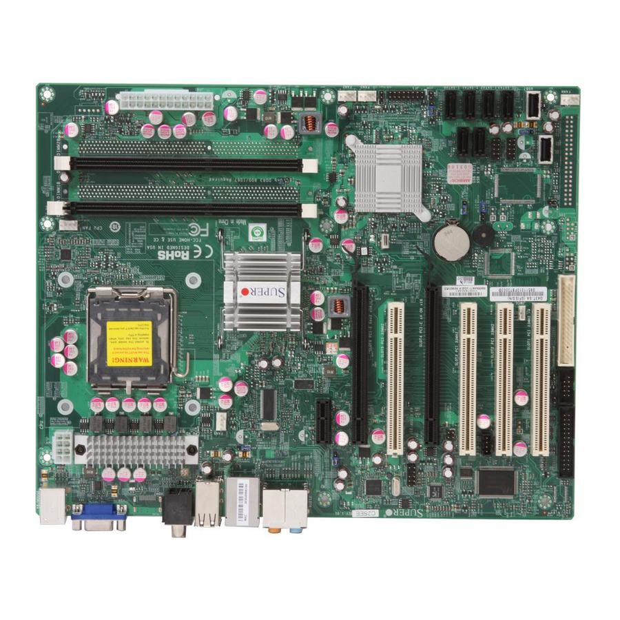
Checklist Congratulations on purchasing your computer motherboard from an acknowledged leader in the industry. Supermicro boards are designed with the utmost attention to detail to provide you with the highest standards in quality and performance. Please check that the following items have all been included with your motherboard. - Page 10 C2SEA/C2SEE User’s Manual C2SEA Motherboard Image Note: All pictures and drawings shown in this manual were based upon the latest PCB Revision available at the time of publishing of the manual. The motherboard you have received may or may not look exactly the same as...
-
Page 11: Important Notes To The User
• Jumpers not indicated are for testing only. • See Chapter 2 for detailed information on jumpers, I/O ports and JF1 front panel connections. • " " indicates the location of Pin 1. Differences between the C2SEA and C2SEE Models C2SEA Chipset Intel G45... -
Page 12: C2Sea/C2See Quick Reference
C2SEA/C2SEE User’s Manual PCIEx1 PCIE Gen2 x16 CTRL PCI 33 MHz PCIE x4 on x16 PCI 33 MHz S I/O PCI 33 MHz PCI 33 MHz Printer C2SEA/C2SEE Quick Reference Jumper Label Description JBT1 CMOS Clear Onboard Speaker Enable C1/JI... - Page 13 Connector Label 1394_1, 1394_2 19/20 Audio, CD1, FP 7, 13, Audio, S/PDIF_Out 10, 4 COM 1 Fans 1-5 44, 41, 40, 22, HDMI JLED JPW1, JPW2 JWOL JWOR Printer LAN1 SATA 0-5 29, 28, 27, 26, 33, 32 SPKR1 USB 0~1, 2~5 6, 5 USB 6, 7, 8~9, 23, 24,...
-
Page 14: Motherboard Features
• One (1) PCI-Express x1 (Slot7) • Two (2) 32-bit PCI 33MHz (Slot1, Slot2) (C2SEA) • Four (4) 32-bit PCI 33MHz (Slot1, Slot2, Slot3, and Slot5) (C2SEE) BIOS • 8 Mb Firmware SPI AMI Flash BIOS • DMI 2.3, PCI 2.3, ACPI 1.0/2.0/3.0, SMBIOS 2.5, Plug and Play (PnP), and... - Page 15 ACPI Features • Slow blinking LED for suspend state indicator • BIOS support for USB keyboard • Main switch override mechanism • External modem ring-on Onboard I/O • Built in ICH10 SATA Controller, 6 connectors for up to 6 devices •...
-
Page 16: Block Diagram
FSB: 1333/1066/800 PCIE_x16 MUX & Level Shift PCIE_X1 Realtek RTL8111C PCIE_x1 ICH10 PCI_E x1 Slot PCI_32_BUS ITE 8213F IDE PCI 32 x4 (C2SEE) PCI 32 x2 (C2SEA) TI TSB43AB22A SPI EEPROM Realtek ALC888 Parallel C2SEA/C2SEE PCI_E x16 HDMI(C2SEA) -
Page 17: Chipset Overview
Chipset Overview The Intel G45/G43 Express Chipset is specially designed for use with Intel Core™ 2 Extreme/Core Quad/Core Duo LGA 775 processors. It consists of two primary com- ponents: the Graphics and Memory Controller Hub (GMCH), and the I/O Controller Hub (ICH10). -
Page 18: Recovery From Ac Power Loss
BIOS chapter of this manual to change this setting. The default set- ting is Power-Off. PC Health Monitoring This section describes the PC health monitoring features of the C2SEA/C2SEE. The motherboard has an onboard System Hardware Monitor chip that supports PC health monitoring. -
Page 19: Wake-On-Lan (Wol)
It is even more important for processors that have high CPU clock rates of 1 GHz and faster. C2SEA/C2SEE accommodates 12V ATX power supplies. Although most power supplies generally meet the specifi cations required by the CPU, some are inadequate. -
Page 20: Versatile Media Capabilities
I/O Virtualization Technology (VT-d) With the Intel ICH10 built in, the C2SEA/C2SEE supports I/O Virtualization Technology (VT-d) that enables multiple operating systems and applications to run in independent partitions. Each partition uses its own subset of host physical memory, and behaves like a virtual machine (VM), providing isolation and protection across multiple partitions. -
Page 21: Chapter 2: Installation
Static-Sensitive Devices Electrostatic Discharge (ESD) can damage electronic com ponents. To prevent dam- age to your system board, it is important to handle it very carefully. The following measures are generally suffi cient to protect your equipment from ESD. Precautions •... -
Page 22: Motherboard Installation
C2SEA/C2SEE User's Manual Motherboard Installation All motherboards have standard mounting holes to fi t different types of chassis. Make sure that the locations of all the mounting holes for both motherboard and chassis match. Although a chassis may have both plastic and metal mounting fasteners, metal ones are highly recommended because they ground the mother- board to the chassis. -
Page 23: Processor And Heatsink Installation
Processor and Heatsink Installation Warning: When handling the processor package, avoid placing direct pressure on the label area of the fan. Notes: 1. Always connect the power cord last and always remove it before add- ing, removing or changing any hardware components. Make sure that you install the processor into the CPU LGA 775 socket before you install the CPU heatsink. - Page 24 C2SEA/C2SEE User's Manual 3. Use your thumb and your index fi n- ger to hold the CPU at the top center edge and the bottom center edge of the CPU. 4. Align CPU Pin1 (the CPU corner marked with a triangle) against the socket corner that is marked with a triangle cutout.
- Page 25 Installing the Heatsink 1. Locate the CPU Fan on the mother- board. (Refer to the layout on the right for the CPU Fan location.) 2. Position the heatsink in such a way that the heatsink fan wires are closest to the CPU fan and are not interfered with other components.
- Page 26 C2SEA/C2SEE User's Manual 8. Repeat Step 6 to insert all four heatsink fasteners into the mounting holes. 9. Once all four fasteners are securely insert- ed into the mounting holes and the heatsink is properly installed on the motherboard, con- nect the heatsink fan wires to the CPU Fan connector.
-
Page 27: Installing Dimms
Memory Support The C2SEA motherboard supports up to 8 GB Unbuffered non-ECC DDR3@1333/1066/800 MHz in 4 DIMMs, and the C2SEE board supports up to 4 GB Unbuffered non-ECC DDR3@1333/1066/800 MHz in 2 DIMMs. Populating DIMM1A,DIMM2A, and/or DIMM1B, DIMM2B with memory modules of the same size and of the same type will result in dual channel, two-way interleaved memory which is faster than the single channel, non-interleaved memory. -
Page 28: Installing And Removing Dimms
C2SEA/C2SEE User's Manual Possible System Memory Allocation & Availability System Device Size Firmware Hub fl ash memory (System 1 MB BIOS) Local APIC 4 KB Area Reserved for the chipset 2 MB I/O APIC (4 Kbytes) 4 KB PCI Enumeration Area 1... -
Page 29: Control Panel Connectors/Io Ports
The I/O ports are color coded in conformance with the PC 99 specifi cation. See The fi gure below for the colors and locations of the various I/O ports. 1. Back Panel Connectors/IO Ports C2SEA/C2SEE Back Panel I/O Port Locations and Defi nitions Back Panel Connectors 1. -
Page 30: Front Control Panel
These connectors are designed specifi - cally for use with Supermicro server chassis. See Figure 2-4 for the descriptions of the various control panel buttons and LED indicators. Refer to the following section for descriptions and pin defi... -
Page 31: Front Control Panel Pin Defi Nitions
(for any hard drives on the system, including SAS and Serial ATA). See the table on the right for pin defi nitions. Fan1 Fan5 Intel G45 (C2SEA) G43 (C2SEE) Slot7 PCI-E x1 C2SEA/C2SEE JPL1 Slot6 PCI-E Gen2 x16 SPI BIOS Intel CTRL... -
Page 32: Nic1 Led Indicators
C2SEA/C2SEE User's Manual NIC1 LED Indicators The NIC (Network Interface Control- ler) LED connection for GLAN port1 is located on pins 11 and 12 of JF1. Attach NIC LED cables to display network activity. Refer to the table on the right for pin defi nitions. -
Page 33: Reset Button
Note: Do not close or short Pins 1 & 2 since this will cause the system to continuously reboot. Fan1 Fan5 Intel G45 (C2SEA) G43 (C2SEE) Slot7 PCI-E x1 C2SEA/C2SEE JPL1 Slot6 PCI-E Gen2 x16 SPI BIOS Intel CTRL... -
Page 34: Connecting Cables
C2SEA/C2SEE User's Manual Connecting Cables ATX/Auxiliary Power Connectors A 24-pin main power connector is located at JPW1, and a 8-pin power connector is located at JPW2 on the motherboard. These power connectors meet the SSI EPS 12V specifi cation. Note: The 8-pin 12V PWR sup- ply is also required to provide adequate power to the processor. -
Page 35: Universal Serial Bus (Usb)
A Giga-bit Ethernet port is located above USB Ports 0~1 on the IO back- plane. This GLAN port accepts RJ45 type cables. Fan5 Intel G45 (C2SEA) G43 (C2SEE) Slot7 PCI-E x1 C2SEA/C2SEE JPL1 Slot6 PCI-E Gen2 x16 SPI BIOS CTRL... -
Page 36: Chassis Intrusion
C2SEA/C2SEE User's Manual Overheat LED/Fan Fail (JOH) The JOH header is used to connect an LED to provide warning of chassis overheating. This LED will blink to in- dicate a fan failure. Refer to the table on right for pin defi nitions. -
Page 37: Fan Headers
Fan Headers The C2SEA/C2SEE has fi ve chassis fan headers (Fan 1 to Fan 5). Fan 1 is the CPU Fan. Fan 2 to Fan 5 are system/ chassis fans. Note: Pins 1-3 of a 4-pin fan headers are backward compatible with the tradi- tional 3-pin fans. -
Page 38: Atx Ps/2 Keyboard And Ps/2 Mouse Ports
C2SEA/C2SEE User's Manual ATX PS/2 Keyboard and PS/2 Mouse Ports The ATX PS/2 keyboard and the PS/2 mouse are located on the backplane. See the table on the right for pin defi ni- tions. (The mouse port is above the keyboard port. -
Page 39: Wake-On-Ring
(You must also have a LAN card with a Wake-On-LAN connector and cable to use this feature.) Fan1 Fan5 Intel G45 (C2SEA) G43 (C2SEE) Slot7 PCI-E x1 C2SEA/C2SEE JPL1 Slot6 PCI-E Gen2 x16 SPI BIOS CTRL CMOS CLEAR... -
Page 40: High-Defi Nition Audio (Hda)
C2SEA/C2SEE User's Manual High-Defi nition Audio (HDA) The C2SEA/C2SEE features a 7.1+2 Channel High-Defi nition Audio (HDA) (J8) codec that provides 10 DAC channels, simultaneously supporting 7.1 sound playback and two channels of independent stereo sound output (multiple streaming) through the front panel stereo out for the front L&R, rear L&R, center and subwoofer... -
Page 41: Front Panel Audio Header
fi ts your cable's connector. Only one CD header can be used at any one time. See the tables at right for pin defi nitions. Fan1 Fan5 Intel G45 (C2SEA) G43 (C2SEE) Slot7 PCI-E x1 C2SEA/C2SEE JPL1 Slot6 PCI-E Gen2 x16 SPI BIOS CTRL... -
Page 42: S/Pdif_Out Connector
C2SEA/C2SEE User's Manual S/PDIF_Out Connector An S/PDIF_Out connector is located next to the Backpanel USB ports on the moth- erboard. The S/PDIF(Sony/Philips Digital Interface Format) connector is used for transporting stereo digital audio signals. It is commonly used to connect the output of a DVD player to a home theater receiver that supports Dolby Digital or DTS surround sound. -
Page 43: 1394_1/1394_2 Connections
LED Indication of power supplied to the system. See the table on the right for pin defi nitions. Fan1 Fan5 Intel G45 (C2SEA) G43 (C2SEE) Slot7 PCI-E x1 C2SEA/C2SEE JPL1 Slot6 PCI-E Gen2 x16 SPI BIOS CTRL CMOS CLEAR... -
Page 44: Jumper Settings
C2SEA/C2SEE User's Manual Jumper Settings Explanation of Jumpers To modify the operation of the motherboard, jumpers can be used to choose between optional settings. Jumpers create shorts between two pins to change the function of the connector. Pin 1 is identifi ed with a square solder pad on the printed circuit board. -
Page 45: Watch Dog Enable
1 and 2 of this jumper to use this feature. See the table on the right for jumper settings. The default setting is Enabled. Fan1 Fan5 Intel G45 (C2SEA) G43 (C2SEE) Slot7 PCI-E x1 C2SEA/C2SEE JPL1 Slot6 PCI-E Gen2 x16 SPI BIOS CTRL... -
Page 46: Pci/Pci-Exp. Slots To Smb Speeds
C2SEA/C2SEE User's Manual PCI/PCI-E Slots to SMB Speeds Jumpers JI C1/JI C2 allow you to connect PCI/PCI-Exp. Slots to the System Manage- ment Bus. The default setting is open to disable the connection. See the table on the right for jumper settings. -
Page 47: Ide Enable/Disable
JPAC enables or disables the onboard audio connections. See the table on the right for jumper settings. The default setting is Enabled. Fan1 Fan5 Intel G45 (C2SEA) G43 (C2SEE) Slot7 PCI-E x1 C2SEA/C2SEE JPL1 Slot6 PCI-E Gen2 x16 SPI BIOS CTRL CMOS CLEAR... -
Page 48: Usb Wake-Up
C2SEA/C2SEE User's Manual USB Wake-Up Use JPUSB jumpers to "wake-up" your system by pressing a key on a USB keyboard or by clicking the USB mouse of your system. The JPUSB jumpers are used together with the USB Wake-Up feature in the BIOS. Enable both the jumpers and the BIOS setting to allow the system to "wake-up via USB devices". -
Page 49: Onboard Speaker Enable
Close pins 3-4 to use the onboard speaker. Connect a cable to pins 1-4 to use an external speaker. Fan1 Fan5 Intel G45 (C2SEA) G43 (C2SEE) Slot7 PCI-E x1 C2SEA/C2SEE JPL1 Slot6 PCI-E Gen2 x16 SPI BIOS CTRL CMOS CLEAR... -
Page 50: Onboard Indicators
C2SEA/C2SEE User's Manual Onboard Indicators GLAN LED Indicators There is a Gigabit-LAN port (LAN1) on the motherboard. This Gigabit Ethernet LAN port has two LED indicators. The yellow LED indicates activity; while the Link LED may be green, amber or off to indicate the speed of the connection. -
Page 51: Led Location
LED is on, the power is on. Unplug the power cable before removing or installing components. See the layout below for the LED location. Fan1 Fan5 Intel G45 (C2SEA) G43 (C2SEE) Slot7 PCI-E x1 C2SEA/C2SEE JPL1 Slot6 PCI-E Gen2 x16 SPI BIOS CTRL CMOS CLEAR... -
Page 52: Parallel Port Connector
C2SEA/C2SEE User's Manual Parallel Port Connector and IDE Hard Drive Connections Note the following when connecting the hard disk drive cables: • A red mark on a wire typically designates the location of pin 1. Parallel Port Connector The parallel (printer) connector is located at J13 on the motherboard. -
Page 53: Ide Connector
Pin 2 of JPD1 to enable the IDE connector before using it. See the table on the right for pin defi nitions. Fan1 Fan5 Intel G45 (C2SEA) G43 (C2SEE) Slot7 PCI-E x1 C2SEA/C2SEE JPL1 Slot6 PCI-E Gen2 x16 SPI BIOS CTRL... - Page 54 C2SEA/C2SEE User's Manual Notes 2-34...
-
Page 55: Chapter 3: Troubleshooting
Troubleshooting Troubleshooting Procedures Use the following procedures to troubleshoot your system. If you have followed all of the procedures below and still need assistance, refer to the ‘Technical Support Procedures’ and/or ‘Returning Merchandise for Service’ section(s) in this chapter. Always disconnect the AC power cord before adding, changing or installing any hardware components. -
Page 56: No Video
C2SEA/C2SEE User's Manual Turn the power switch on and off to test the system. The battery on your motherboard may be old. Check to verify that it still sup- plies ~3VDC. If it does not, replace it with a new one. -
Page 57: Technical Support Procedures
Technical Support Procedures Before contacting Technical Support, please take the following steps. Also, note that as a motherboard manufacturer, Supermicro does not sell directly to end-users, so it is best to fi rst check with your distributor or reseller for troubleshooting services. - Page 58 Question: How do I utilize the onboard HD sound? Answer: The onboard HD sound available on the C2SEA/C2SEE can be enabled with the audio driver software that was included in your motherboard package. When activated, sound will be routed through the jacks next to the LAN Port according to the audio connection descriptions listed on Page 2-8.
-
Page 59: Returning Merchandise For Service
Chapter 3: Troubleshooting Answer: Because the chipset does not support memory remapping, and PCI-E memory requires a great deal of memory, so there is a memory hole located around the 4GB memory address. Question: How do I connect the ATA100/66 cable to my IDE device(s)? Answer: The 80-wire/40-pin high-density ATA100/66 IDE cable that came with your system has two connectors to support two drives. - Page 60 C2SEA/C2SEE User's Manual Notes...
-
Page 61: Chapter 4: Bios
Introduction This chapter describes the AMI BIOS Setup Utility for the C2SEA/C2SEE. The AMI ROM BIOS is stored in a Flash EEPROM and can be easily updated. This chapter describes the basic navigation of the AMI BIOS Setup Utility setup screens. -
Page 62: Main Setup
C2SEA/C2SEE User’s Manual screens. An AMI BIOS identifi cation string is displayed at the left bottom corner of the screen, below the copyright message. Warning!! Do not shut down or reset the system while updating BIOS to prevent possible boot failure. - Page 63 Chapter 4: AMI BIOS Processor When you select this option, the AMI BIOS will automatically display the status of processors as shown below: Speed Count Core System Memory This option allows the AMI BIOS to display the status of memory modules installed in the system.
-
Page 64: Advanced Setup
C2SEA/C2SEE User’s Manual Advanced Setup Confi gurations Use the arrow keys to select Boot Setup and hit <Enter> to access the submenu items: BIOS Features QuickBoot If Enabled, this option will skip certain tests during POST to reduce the time needed for system boot. -
Page 65: Acpi Configuration
ACPI Confi guration Use this feature to confi gure ACPI (Advanced Confi guration and Power Interface) power management settings for your system. ACPI Aware OS Select Yes to enable ACPI support for the OS. Disable this feature if ACPI is not supported by your OS. -
Page 66: Processor & Clock Options
C2SEA/C2SEE User’s Manual Processor & Clock Options Warning When you fi rst enter the Advanced Setup screen, the Setup Warning will be displayed. Follow the instructions and set the correct value for each item to ensure that the system functions properly. -
Page 67: Advanced Chipset Settings
it cannot, thus preventing a worm or a virus from creating a fl ood of codes to overwhelm the processor or damage the system during an attack. The default is Enabled. (Refer to Intel and Microsoft Web Sites for more information.) Core-Multi-Processing (Available when supported by the CPU) Set to Enabled to use a processor's Second Core and beyond. -
Page 68: Video Function Confi Guration
C2SEA/C2SEE User’s Manual Confi guring DRAM Timing by SPD Select Enable to allow the BIOS to read the SPD (Serial Presence Detect) chip which is built in the memory module in order to get the exact memory specifi ca- tions. The options are Enabled and Disabled. - Page 69 DVMT/Fixed Memory This option allows the user to set the amount of memory to be used for the operation of DVMT/Fixed Mode. The options are 128 MB, 256 MB and Maximum DVMT. Flat Panel Type This option allows the user to select the Flat Panel Type. The options are Type 1~ Type 16.
- Page 70 C2SEA/C2SEE User’s Manual Active State Power Management Select Enabled to enable Active-State Power Management for signal transactions between L0 and L1 Links on the PCI Express Bus in order to maximize power- saving and transaction speeds. The options are Enabled and Disabled.
-
Page 71: Usb Configuration
Chapter 4: AMI BIOS USB Confi guration This feature allows the user to confi gure USB settings for the motherboard. USB Devices Enabled This item displays the USB devices that are detected by the BIOS. Legacy USB Support Select Enabled to use Legacy USB devices. If this item is set to Auto, Legacy USB support will be automatically enabled if a legacy USB device is installed on the motherboard, and vise versa. - Page 72 C2SEA/C2SEE User’s Manual Confi gure SATA#1 As This feature allows the user to select the drive type for SATA#1. The options are IDE and AHCI. Primary IDE Channels Master/Slave, Secondary IDE Channels Maser/Slave and Third IDE Channels Maser/Slave These settings allow the user to set the parameters of Primary IDE Master/Slave, Secondary IDE Master/Slave and Third IDE Master/Slave slots.
- Page 73 DMA Mode Select Auto to allow the BIOS to automatically detect IDE DMA mode when the IDE disk drive support cannot be determined. Select SWDMA0 to allow the BIOS to use Single Word DMA mode 0. It has a data transfer rate of 2.1 MBs. Select SWDMA1 to allow the BIOS to use Single Word DMA mode 1.
-
Page 74: Pcipnp Configuration
C2SEA/C2SEE User’s Manual Hard Disk Detect Time Out Use this feature to set the system time-out value to allow the BIOS to detect the HDD devices installed in the system. The options are Disabled, 1, 2, 3, 4, 5, 6, and 7 (seconds). -
Page 75: Super Io Configuration
Chapter 4: AMI BIOS PCI Slot1~Slot5 Select Yes to enable OPROM for a PCI slot specifi ed. The options are Yes (to en- able OPROM for the slot specifi ed) and No. Load Onboard LAN Option ROM Select Enabled to load the onboard LAN Option ROM. The options are Enabled and Disabled. -
Page 76: Remote Access Configuration
C2SEA/C2SEE User’s Manual Remote Access Confi guration Remote Access This feature allows the user to enable the function of Remote Access. The options are Disabled and Enabled. If the item Remote Access is set to Enabled, the following items will display: Serial Port Mode This feature allows the user to set the serial port mode for Console Redirection. -
Page 77: Hardware Health Configuration
Hardware Health Confi guration This feature allows the user to monitor Hardware Health of the system and review the status of each item when displayed. System Temperature, CPU Temperature Fan Speed Control Modes This feature allows the user to decide how the system controls the speeds of the onboard fans. -
Page 78: Security Setup
C2SEA/C2SEE User’s Manual Security Settings The AMI BIOS provides a Supervisor and a User password. If you use both pass- words, the Supervisor password must be set fi rst. Supervisor Password Is: This item indicates if a supervisor password has been entered for the system. Clear means such a password has not been used and Set means a supervisor password has been entered for the system. -
Page 79: Boot Configuration
Boot Confi guration Use this feature to confi gure Boot Settings: Boot Device Priority This feature allows the user to specify the sequence of priority for the Boot De- vice. The settings are 1st Floppy Drive and Disabled. The default settings are the fol- lowing: •... -
Page 80: Exit
C2SEA/C2SEE User’s Manual Exit Options Select the Exit tab from the AMI BIOS Setup Utility screen to enter the Exit BIOS Setup screen. Save Changes and Exit When you have completed the system confi guration changes, select this option to leave the BIOS Setup Utility and reboot the computer, so the new system con- fi... - Page 81 Chapter 4: AMI BIOS Load Fail-Safe Defaults To set this feature, select Load Fail-Safe Defaults from the Exit menu and press <Enter>. The Fail-Safe settings are designed for maximum system stability, but not for maximum performance. 4-21...
- Page 82 C2SEA/C2SEE User’s Manual Notes 4-22...
-
Page 83: Appendix A: Amibios Error Beep Codes
Appendix A BIOS Error Beep Codes During the POST (Power-On Self-Test) routines, which are performed each time the system is powered on, errors may occur. Non-fatal errors are those which, in most cases, allow the system to continue the boot-up process. The error messages normally appear on the screen. Fatal errors are those which will not allow the system to continue the boot-up procedure. - Page 84 C2SEA/C2SEE User’s Manual Notes...
-
Page 85: Installing The Windows Os
After the Windows XP/2000/2003 OS Installation is completed, the system will automatically reboot. Insert the Supermicro Setup CD that came with your motherboard into the CD Drive during system boot, and the main screen as shown on Page C-1 will display. Follow the instructions given in Appendix C to complete other... - Page 86 C2SEA/C2SEE User's Manual Notes...
-
Page 87: Software Installation Instructions
Software Installation Instructions C-1 Installing Drivers After you've installed the Windows Operating System, a screen as shown below will appear. You are ready to install software programs and drivers that have not yet been installed. To install these software programs and drivers, click the icons to the right of these items. - Page 88 C2SEA/C2SEE User's Manual C-2 Confi guring Supero Doctor III The Supero Doctor III program is a Web-base management tool that supports remote management capability. It includes Remote and Local Management tools. The local management is called the SD III Client. The Supero Doctor III program included on the CDROM that came with your motherboard allows you to monitor the environment and operations of your system.
- Page 89 Supero Doctor III Interface Display Screen-II (Remote Control) Note: SD III Software Revision 1.0 can be downloaded from our Web site at: ftp://ftp.supermicro.com/utility/Supero_Doctor_III/. You can also download SDIII User's Guide at: http://www.supermicro.com/PRODUCT/ Manuals/SDIII/UserGuide.pdf. For Linux, we will still recommend that you...
- Page 90 C2SEA/C2SEE User's Manual Notes...
- Page 91 (Disclaimer continued) The products sold by Supermicro are not intended for and will not be used in life support systems, medical equipment, nuclear facilities or systems, aircraft, aircraft devices, aircraft/emergency communication devices or other critical systems whose failure to perform be reasonably expected to result in signifi cant injury or loss of life or catastrophic property damage.
Need help?
Do you have a question about the C2SEE and is the answer not in the manual?
Questions and answers