Table of Contents
Advertisement
Quick Links
Operation Manual
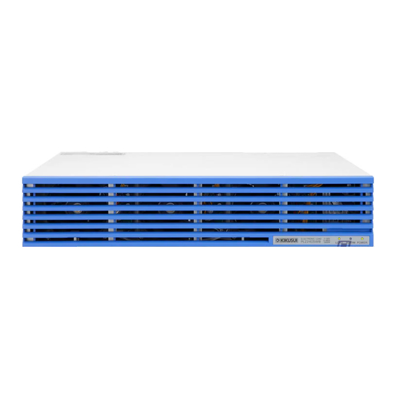
Electronic load booster
PLZ2405WB
This product can be connected in parallel with a PLZ1205W electronic
load to increase input current. You can connect up to four units to a
single PLZ1205W. The PLZ1205W operates as a master unit and the
PLZ2405WB as a slave unit.
Number of boosters
Maximum power
1 unit
3 600 W
2 units
6 000 W
3 units
8 400 W
4 units
10 800 W
About this manual
This manual contains an overview of the PLZ2405WB electronic load
booster and information about connection, specifications, and the
like. For information on how to perform parallel operation, see the
PLZ1205W Series Electronic Load User's Manual.
These manuals are intended for users of this product and their
instructors. Explanations are given under the presumption that the
reader has knowledge of power supplies.
Every effort has been made to ensure the accuracy of this manual.
However, if you have any questions or find any errors or omissions,
please contact your Kikusui agent or distributor.
If you find any misplaced or missing pages in the manuals, they will
be replaced. If the manual gets lost or soiled, a new copy can be
provided for a fee. In either case, please contact your Kikusui agent
or distributor. At that time, inform your agent or distributor of the "Part
No." written on the front cover of this manual.
After you have finished reading this manual, store it so that you can
use it for reference at any time.
PLZ2405WB
PART NO. Z1-006-330, I0034101
Jan 2021
Maximum current
720 A
1 200 A
1 680 A
2 160 A
Features
•
Connecting the maximum of number of boosters (four) in parallel
with the PLZ1205W (master unit) creates a 10.8 kW, 2 160 A load.
The master unit shows the total current and total power. The entire
set of units connected in parallel can be used as a single load.
•
Connection is easy. Only a single signal cable needs to be con-
nected between the master unit and a booster and between each
booster.
•
There is no power switch. The on and off of the AC input power
supply is controlled by the master unit.
Checking the Package Contents
Check that all accessories are included and that the main unit and
accessories have not been damaged during transportation. If the main
unit or any of the accessories are damaged or missing, contact your
Kikusui agent or distributor. We recommend that you save all packing
materials, in case the product needs to be transported at a later date.
Accessories
The attached power cord varies depending on the shipment destination.
or
Rating: 125 V/10A
Rateing: 250 V and 10A
Plug: NEMA5-15
Plug: CEE7/7
[85-AA-0004]
[85-10-1070]
Power cord (1 pc., length: 2.5 m)
Top
[Q1-500-158]
Bottom
[Q1-500-159]
Load input terminal cover
[M1-100-134]
[M5-101-009]
[M4-100-009]
[M5-100-009]
Load input terminal screw set
(2 sets)
Operation manual
(this manual; 1 copy)
China RoHS sheet (1pc.)
KIKUSUI ELECTRONICS CORP.
1-1-3, Higashiyamata, Tsuzuki-ku, Yokohama,
224-0023, Japan
TEL: +81-45-482-6353 Fax: +81-45-482-6261
www.kikusui.co.jp/en
or
Rating: 250 V and 10A
Plug: GB1002
[85-10-0791]
Ferrite Core
Cable
Parallel operation signal
cable kit (PC01-PLZ-5W)
Screws for the load input
terminal cover (2 pcs.)
[M3-112-018]
Safety Information (1pc.)
1
Advertisement
Table of Contents

Related Manuals for Kikusui PLZ2405WB


Summary of Contents for Kikusui PLZ2405WB
- Page 1 If the manual gets lost or soiled, a new copy can be Load input terminal cover Parallel operation signal provided for a fee. In either case, please contact your Kikusui agent cable kit (PC01-PLZ-5W) or distributor. At that time, inform your agent or distributor of the “Part No.”...
- Page 2 Notations Used in this Manual Component Names Front panel • In this manual, the PLZ1205W and PLZ2405WB are sometimes referred to as a load. • The PLZ1205W is sometimes referred to as the master unit. • The PLZ2405WB is sometimes referred to as a booster.
- Page 3 [A] (53.49) (67.43) (85.01) (107.2) Booster (PLZ2405WB) 1. Excerpt from Japanese laws related to electrical equipment. Booster (PLZ2405WB) —Note— A cable’s temperature is determined by the resistive loss based on the current, the ambient temperature, and the cable’s external thermal resistance.
- Page 4 DUT. Example: Connection of two boosters. Master unit (PLZ1205W) − − Booster (PLZ2405WB) Place the bottom half of the load input terminal cover underneath the load input terminals. Booster (PLZ2405WB) This completes the procedure for connecting the load cables.
- Page 5 3 m or less in length. If obtain- Turn the master unit’s POWER switch off. This will also turn the ing a power cord is difficult, contact your Kikusui agent or distributor. boosters off.
- Page 6 Electrical specifications The product is calibrated before shipment. To maintain long-term per- formance, we recommend periodic calibration. Unless specified otherwise, the specifications are for the following To have your PLZ2405WB calibrated, contact your Kikusui agent or settings and conditions. distributor. •...
- Page 7 6. Pollution is addition of foreign matter (solid, liquid or gaseous) that may pro- duce a reduction of dielectric strength or surface resistivity. Pollution Degree 2 assumes that only non-conductive pollution will occur except for an occasional temporary conductivity caused by condensation. PLZ2405WB...
- Page 8 Copyright Reproduction and reprinting of this operation manual, whole or par- tially, without our permission is prohibited. Both unit specifications and manual contents are subject to change without notice. © 2016 Kikusui Electronics Corporation PLZ2405WB...
Need help?
Do you have a question about the PLZ2405WB and is the answer not in the manual?
Questions and answers