Sign In
Upload
Manuals
Brands
Kikusui Manuals
Power Supply
PLZ2405WB
Kikusui PLZ2405WB Manuals
Manuals and User Guides for Kikusui PLZ2405WB. We have
2
Kikusui PLZ2405WB manuals available for free PDF download: User Manual, Operation Manual
Kikusui PLZ2405WB User Manual (134 pages)
Electronic Load
Brand:
Kikusui
| Category:
Extender
| Size: 4 MB
Table of Contents
Table of Contents
1
About Operation Manual
2
Checking the Package Contents
3
Product Overview
3
Notations Used in this Manual
4
Safety Precautions
4
Precautions Concerning Installation Location
4
Contents
5
Component Names
8
Installation and Preparation
12
Rack Mounting the PLZ-5W Series
12
Removing the Handle and the Rubber Feet
12
Attaching the Rack Adapter or Bracket
12
Connecting the Power Cord
13
Checking Whether the Power Is on or off
14
Turning the Power on
14
Turning the Power off
14
Connecting to the Load Input Terminals
15
Connecting to the Load Input Terminals on the Rear Panel
15
Connecting to the Load Input Terminals on the Front Panel
17
Notes Regarding Load Input Terminals
18
Basic Functions
19
Panel Operations
19
Using the Function Keys
19
Inputting Numbers/Characters
20
Load On/Load off
20
Setting the Operation Mode
21
Setting Constant Current (CC) Mode
21
Setting Constant Resistance (CR) Mode
21
Setting Constant Voltage (CV) Mode
22
Setting Constant Power (CP) Mode
22
Adding CV Mode to CC Mode (CC+CV)
23
Adding CV Mode to CR Mode (CR+CV)
24
Setting Arbitrary I-V Characteristics (ARB) Mode
25
Setting the Current Range / Voltage Range
27
Setting the Slew Rate
27
Setting the Short Function
28
Switching Function
29
Setting the Switching Level
29
Setting the Switching Interval
29
Turning the Switching Function On/Off
31
Timing of Trigger Signal Output
31
Alarm Function
32
Alarm Types and Operation
32
Setting Overcurrent Protection (OCP)
33
Setting Overpower Protection (OPP)
33
Setting Undervoltage Protection (UVP)
34
Setting Watchdog Protection (WDP)
35
When an Alarm Occurs
35
Clearing an Alarm
35
Measurement Function
36
Overview of the Measurement Function
36
Starting/Stopping Measurement
36
Obtaining the Measurement Data
36
Setting Triggers
37
Recording Integrated Data
39
Recording Current Capacity/Power Capacity/Elapsed Time
39
Displaying the Integrated Data
40
Advanced Functions
41
Changing the Response Speed
41
Soft Start
42
Remote Sensing
43
Connecting the Sensing Cables
43
Enabling Remote Sensing
44
Trigger Function
45
Auto Load off Timer
45
Types of Memory
46
ABC Preset Memories
47
Saving to ABC Preset Memories
47
Recalling ABC Preset Memory Entries
48
Setup Memory
48
Saving to the Setup Memory
48
Recalling the Setup Memory
49
Checking the Setup Memory Details
49
Synchronized Operation
50
Connection for Synchronized Operation
50
Synchronizing the Load On/Off Operation
51
Synchronizing Measurements
52
Synchronizing the Start of Sequences
52
Synchronizing the Resuming of Sequences
53
Remote Control
54
Releasing Remote Control
54
Sequence Function
55
Overview of the Sequence Function
55
Programs and Steps
55
Main Features
55
Program Settings
56
How to View the Program Editing Screen
56
Creating a Program
56
Setting the Number of Loops of a Program
57
Setting the Voltage of CV Mode Addition (+CV)
57
Setting Protection Functions
58
Changing a Program Name
58
Deleting a Program
59
Setting Steps
60
Creating Steps
60
Deleting a Step
62
Sequence Creation Tutorial
62
Newly Creating Program1
63
Registering Steps to Program1
63
Executing, Pausing, and Stopping Sequences
66
Executing a Sequence
66
Pauses the Sequence
66
Stopping a Sequence
67
Setting Triggers
67
External Control
69
Preparation for External Control
69
Precautions for High-Speed Load Simulations
69
Connecting the EXT CONT Connector
70
EXT CONT Connector Pin Arrangement
71
Load Setting Control
72
Constant Current (CC), Constant Resistance (CR), and Constant Power (CP) Control
72
Constant Voltage (CV) Control
73
Controlling the Current to be Superimposed on the Constant Current (CC)
74
Control of Load On/Load off
75
Load On/Off Control Input
75
Load-On Status Signal Output
76
Control of the Current Range
76
Range Control Input
76
Range Status Output
76
Control of the Alarm Signal
77
Alarm Input
77
Alarm Clearing Input
77
Alarm Status Output
77
Trigger Input/Output
78
Trigger Input
78
Trigger Output
78
Digital I/O
78
Using the Current Monitor Signal
79
Current Monitor Output
79
Parallel Operation
80
Overview of Parallel Operation
80
Parallel Operation Using the same Model
81
Performing Connections for Parallel Operation
81
Performing Parallel Operation
83
Slew Rate and Response Speed Settings During Parallel Operation
83
Protection Function During Parallel Operation (Parallel Operation Anomaly Detection)
83
Canceling Parallel Operation
83
System Settings
84
Displaying/Changing the Basic Settings
84
Panel Settings at Startup
85
Screen Saver
85
Key Lock
86
Setting the Beep Sound
87
Setting the DIGITAL2 Signal Input/Output
87
Displaying/Changing the Interface Settings
88
Resetting the Interface Settings
89
Returning the Interface Settings to the Factory Default Settings
89
Displaying SCPI Errors
90
Setting the Date/Time
90
Factory Default Settings and Reset Settings
91
Restoring the Factory Default Settings
91
Restoring the Reset Settings
91
Main Settings at Factory Default and at Reset
92
Updating
94
Displaying the Device Information
94
Maintenance
95
Inspection
95
Cleaning the Panels
95
Overhaul
95
Backup Battery Replacement
95
Calibration
95
Malfunctions and Causes
96
Specifications
98
Ratings
98
Constant Current (CC) Mode
98
Constant Resistance (CR) Mode
99
Constant Voltage (CV) Mode
99
Constant Power (CP) Mode
100
Arbitrary I-V Characteristics (ARB) Mode
100
Measurement Function
100
Switching Function
101
Slew Rate
101
Soft Start
101
Alarm Feature
102
Sequence Function
102
Other Functions
103
Common Specifications
103
General Specifications
105
External Dimensions
106
Appendix
107
Selecting the Load Cables
107
Methods to Stabilize Operation
108
Reducing the Load Cable Inductance
108
Optimizing the Response Speed
109
Using Remote Sensing
109
Slew Rate for Small Currents
110
Operating Area
111
Basic Operation Modes
111
Operation of the Constant Current (CC) Mode
112
Operation in Constant Resistance (CR) Mode
113
Constant Power (CP) Mode Operation
115
Constant Voltage (CV) Mode Operation
116
Operation When CV Mode Is Added to CC Mode
118
Operation When CV Mode Is Added to CR Mode
119
Operating Area of each Model
121
Response Time and Waveform When an OPP Is Activated
124
Response Time
124
Waveform
124
Main Specifications for Parallel Operation
126
Parallel Operation Using the same Type of Electronic Loads
126
Parallel Operation Using Boosters
128
Options
129
Rack Adapters, Brackets
129
GPIB Converter (PIA5100)
130
Parallel Operation Signal Cable Kit (PC01-PLZ-5W)
130
Low Inductance Cable
130
Large Current Load Cable
130
Index
131
Advertisement
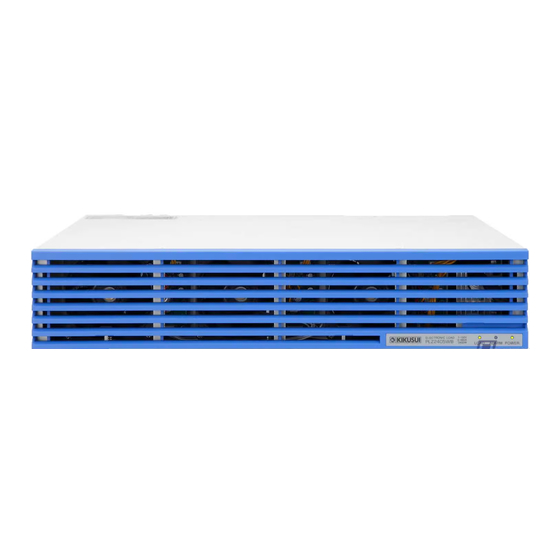
Kikusui PLZ2405WB Operation Manual (9 pages)
Electronic Load Booster
Brand:
Kikusui
| Category:
Power Supply
| Size: 0 MB
Table of Contents
Features
1
Checking the Package Contents
1
About this Manual
1
Component Names
2
Safety Precautions
2
Notations Used in this Manual
2
Notes on Usage
2
Connecting the Master Unit
3
Connecting to the DUT
3
Connecting the DUT
4
Connecting the Power Cord
5
Performing Parallel Operation
5
Rack Mount Brackets
6
Specifications
6
Calibration
6
Outline Drawing
7
Advertisement
Related Products
Kikusui PLZ205W
Kikusui PLZ164W
Kikusui PLZ334W
Kikusui PLZ1004W
Kikusui PLZ164WA
Kikusui PLZ664WA
Kikusui PLZ405W
Kikusui PLZ1205W
Kikusui PCR-L Series
Kikusui PCR4000MA
Kikusui Categories
Power Supply
Test Equipment
Measuring Instruments
Controller
Racks & Stands
More Kikusui Manuals
Login
Sign In
OR
Sign in with Facebook
Sign in with Google
Upload manual
Upload from disk
Upload from URL