Table of Contents
Advertisement
User's Manual
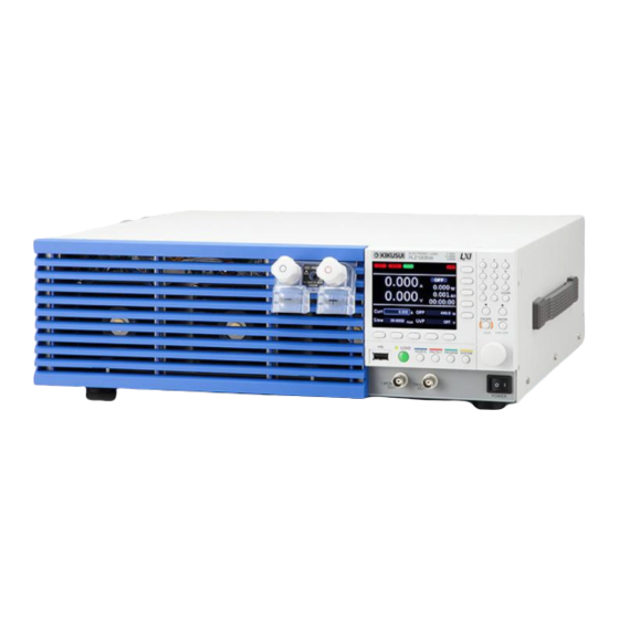
PLZ-5W Series Electronic Load
PLZ205W
PLZ405W
PLZ1205W
PART NO. IB027945
Apr. 2018
Component Names 8
Installation and Preparation 12
Basic Functions 19
Advanced Functions 54
Sequence Function 74
External Control 91
Parallel Operation 105
System Settings 111
Maintenance 127
Specifications 128
Appendix 141
Contents 5
Advertisement
Table of Contents

Related Manuals for Kikusui PLZ205W


Summary of Contents for Kikusui PLZ205W
- Page 1 PART NO. IB027945 Apr. 2018 Contents 5 User’s Manual Component Names 8 PLZ-5W Series Electronic Load Installation and Preparation 12 PLZ205W PLZ405W Basic Functions 19 PLZ1205W Advanced Functions 54 Sequence Function 74 External Control 91 Parallel Operation 105 System Settings 111...
-
Page 2: About The Plz-5W Series Manuals
The specifications of this product and the contents of this sumption that the reader has knowledge of power sup- document are subject to change without prior notice. plies. Copyright© 2016 Kikusui Electronics Corporation PLZ-5W series manual construction • User’s manual (this manual) This manual is intended for first-time users of this prod- uct. -
Page 3: Accessories
Power cord (1 pc., length: 2.5 m) PLZ-5W series lineup [M1-100-119] Top [Q1-500-156] Model Maximum oper- Operating Power ating current voltage PLZ205W 40 A 1 V to 150 V 200 W [M5-101-008] PLZ405W 80 A 1 V to 150 V 400 W [M4-100-008]... -
Page 4: Notations Used In This Manual
Notations Used in This Manual Installation Location When installing this product, be sure to observe the “Pre- • In this manual, electronic load PLZ205W, PLZ405W, or cautions When Choosing the Installation Location” in the PLZ1205W is sometimes referred to as PLZ-5W. -
Page 5: Table Of Contents
Contents About the PLZ-5W Series Manuals ....2 Turning the switching function on/off....39 Timing of trigger signal output ......39 Accessories ............3 Alarm Function ..........40 Product Overview ..........3 Alarm types and operation ........40 Notations Used in This Manual......4 Setting overcurrent protection (OCP) ....42 Safety Precautions ..........4 Setting overpower protection (OPP)..... - Page 6 Digital I/O............103 Sequence Function Using the Current Monitor Signal ....104 Current monitor output ........104 Overview of the Sequence Function....74 Programs and steps ..........74 Main functions ............74 Parallel Operation Program Configuration ........75 How to view the program editing screen ....75 Creating a program ..........75 Overview of Parallel Operation.......105 Setting the number of loops ........76...
- Page 7 Troubleshooting ..........173 Specifications Index ..............175 Ratings ............... 128 Constant current (CC) mode ......129 Constant resistance (CR) mode ......130 Constant voltage (CV) mode ......130 Constant power (CP) mode ........ 131 Arbitrary I-V characteristics (ARB) mode.... 131 Measurement function ........131 Switching function..........
-
Page 8: Component Names
Press the ( ) side to switch the power on, and the ( ) side to switch the p.13 power off. Feet PLZ205W/PLZ405W: 4 locations on bottom panel. p.168 PLZ1205W: 4 locations on bottom panel, 4 locations on side panel. DC INPUT terminal on Used for simple connection with the DUT. - Page 9 Controls Name Function Display area Displays the settings, measured values, and other information. p.10 Function keys Each function key executes the item that is displayed above that key (func- p.20 tion area). Sub-function keys Each sub-function key executes the item that is displayed to the left of that p.20 key (sub-function area).
- Page 10 Display Name Function Selected operation mode. Displays the selected operation mode. p.25 Current range Displays the current range. p.34 Voltage range Displays the voltage range. p.34 Remote Indicates that the product is being controlled remotely. p.73 Operation mode in use Displays the currently running operation mode.
- Page 11 Rear panel PLZ205W PLZ405W (PLZ205W example) 8 9 10 PLZ1205W 8 9 10 Name Function EXT CONT connector External control connector. A cover for the pins is provided. p.91 SENSING connector Remote sensing connector. p.56 DC OUT connector Used during GPIB converter (option) use.
-
Page 12: Installation And Preparation
If the supplied power cord cannot be used because the rated voltage or the plug shape is incompatible, have a qualified engineer replace it with an appropriate power cord that is 3 m or less in length. If obtaining a power cord is difficult, contact your Kikusui agent or distributor. -
Page 13: Checking Whether The Power Is On Or Off
Installation and Preparation Checking Whether the Power Is On or Off Turning the power on POWER switch Check that the power cord is connected correctly. Check that nothing is connected to the DC INPUT (load input) terminals on the front and rear panels. -
Page 14: Connecting To The Dut
Installation and Preparation Connecting to the DUT The PLZ-5W has load input terminals on both its front and rear panels. The specifications of the PLZ-5W are for the load input terminals on the rear panel. For information on selecting load cables, refer to “Selecting the Load Cables” (p.141) in the “Appendix”. -
Page 15: Connecting To The Load Input Terminals On The Rear Panel
Installation and Preparation | Connecting to the DUT Connecting to the load input terminals on the rear panel Connect the DUT to the load input terminals on the rear panel. Risk of electric shock. WARNING • Be sure to attach the cover for the load input terminals on the rear panel. •... - Page 16 Installation and Preparation | Connecting to the DUT Align the tabs of the top cover for the load input terminals on the rear panel with those of the bottom cover. Align the tabs of the load input terminal cover according to the load cable diameter. You can adjust the diameter of the holes that the load cables pass through by changing the posi- tion that the top and bottom covers are put together.
-
Page 17: Connecting To The Load Input Terminals On The Front Panel
Installation and Preparation | Connecting to the DUT Connecting to the load input terminals on the front panel The load input terminals on the front panel enable you to easily connect the DUT to the PLZ-5W. The specifications of the PLZ-5W are for the load input terminals on the rear panel. The load input terminals on the front panel may not meet the specifications. -
Page 18: Notes Regarding Load Input Terminals
Installation and Preparation | Connecting to the DUT Connect the load cables to the output terminals of the DUT. Connect the positive (+) polarity of the load input terminal on the front panel to the positive (+) polarity of the DUT, and the negative (-) polarity of the load input terminal on the front panel to the negative (-) polarity of the DUT. -
Page 19: Basic Functions
Basic Functions Panel Operations This chapter explains the front panel operations in general. Switching the display There are two display modes: function display and main display. The function display shows functions that can be executed on each screen. The main display shows measured values with large numbers. Pressing a menu key shows the function display of the corresponding menu screen. -
Page 20: Using The Function Keys
Basic Functions | Panel Operations Using the function keys On the function display (p.19), the available functions are shown in the function area and sub-function area. You can execute or select the functions by pressing the corresponding function key or sub-function key. - Page 21 Basic Functions | Panel Operations Operation example (Selection of constant resistance mode) Press SOURCE, Mode, and then CR. In the above step example, press the buttons in the following order. Mode Mode LOAD SOURCE SOURCE User’s Manual PLZ-5W...
-
Page 22: Inputting Numbers And Characters
Basic Functions | Panel Operations Inputting numbers and characters You can enter numbers and characters in input areas from the front panel or external keyboard. Number input and character input switch automatically according to the input area. If numbers or characters are selected in an input area, they can be changed. If only a cursor is shown in an input area, you can enter characters or numbers at the cursor position. -
Page 23: Changing Values
Basic Functions | Panel Operations Changing values To change a selected value (e.g., load value), use the numeric keypad or rotary knob. If you enter a value with the numeric keypad, following input, press the ENTER key to confirm the value. Use the numeric keypad or the rotary knob to change the value. -
Page 24: Load On/Off
Basic Functions Load On/Off “Load on” refers to a condition in which a current is running through the PLZ-5W. “Turning the load on” refers to the operation of running a current through the PLZ-5W. Conversely, “load off” refers to a condition in which a current is not running through the PLZ-5W. “Turning the load off”... -
Page 25: Setting The Operation Mode
Basic Functions Setting the Operation Mode The PLZ-5W has the following five operation modes. Mode switching can be done only while the load is off. Constant current (CC) A current value is specified and the current is kept constant even when the voltage mode changes. -
Page 26: Setting The Current In Cc Mode
Basic Functions | Setting the Operation Mode Setting the current in CC mode In CC mode, the current is kept constant even when the voltage changes. For details on CC mode, see “Operation of the constant current (CC) mode” (p.148). Set the operation mode to CC mode (p.25). -
Page 27: Setting The Voltage In Cv Mode
Basic Functions | Setting the Operation Mode Setting the voltage in CV mode In CV mode, the PLZ-5W runs current so that the voltage at the load input end of the PLZ-5W is constant. For details on CV mode, see “Constant voltage (CV) mode operation” (p.152). Set the operation mode to CV mode (p.25). -
Page 28: Setting The Load Value In Cc+Cv Mode
Basic Functions | Setting the Operation Mode Setting the load value in CC+CV mode You can add CV mode in CC mode. For details on CC+CV mode, see “Operation when CV mode is added to CC mode” (p.154). Set the operation mode to CC+CV mode (p.25). Press Level and then Voltage. -
Page 29: Setting The Load Value In Cr+Cv Mode
Basic Functions | Setting the Operation Mode Setting the load value in CR+CV mode You can add CV mode in CR mode. CV mode can be added even while the load is turned on. For details on CR+CV mode, see “Operation when CV mode is added to CR mode” (p.155). Set the operation mode to CR+CV mode (p.25). -
Page 30: Setting The Load Value In Arb Mode
Basic Functions | Setting the Operation Mode Setting the load value in ARB mode In ARB mode, arbitrary I-V characteristics can be set by registering multiple I-V characteristic points (set of voltage value and current value). Three up to 100 points can be registered, and the space between two points is linearly interpolated. - Page 31 Basic Functions | Setting the Operation Mode Basic operations on the I-V characteristics editing screen The left column is voltage, and the right is current. In each row, you can enter a single point of your choice. Edit the selected cell (when the cell can be edited) Selected cell (blue) Use the rotary knob to move...
- Page 32 Basic Functions | Setting the Operation Mode Example: Setting I-V characteristics You can smoothly set the I-V characteristics by first setting the number of rows and then setting the row with the maximum voltage and proceeding to rows with lower voltages. As an example, let’s set the I-V characteristics while referring to the table below.
- Page 33 Basic Functions | Setting the Operation Mode Use the numeric keypad or the rotary knob to enter the cur- rent value “0.8”, and then press ENTER. The current value in row 5 is set to 0.8 A. In the same manner, set the voltage and current values in rows 4 through 2.
-
Page 34: Setting The Current Range And Voltage Range
Press SOURCE and then Range. Use the sub-function keys to set the current range and the voltage range. L range Current Range M range H range L range Voltage range H range PLZ205W example This completes the setting. User’s Manual PLZ-5W... -
Page 35: Setting The Slew Rate
Basic Functions Setting the Slew Rate You can set the speed of change when the current is changed. The slew rate functions in the following cases. • When the setting is changed to change the current value (including the switching function). •... -
Page 36: Setting The Short Function
Basic Functions Setting the Short Function The load input terminals can be shorted artificially by activating the short function. In constant current (CC) mode, the maximum current value, and in constant resistance (CR) mode, the minimum voltage value, is set, and the relay contact (30 Vdc/1 A) of the EXT CONT connector (p.92) closes. -
Page 37: Switching Function
Basic Functions Switching Function Switching refers to the operation of executing two settings repetitively. The switching function is suitable for transient response characteristics testing of regulated DC power supplies. When the switching operation is in progress, a trigger signal is output from the TRIG OUT connector on the front panel (p.39). -
Page 38: Setting The Switching Interval
Basic Functions | Switching Function Setting the switching interval Set the switching interval using the length of time at the high level or the duty ratio (ratio of high level to one cycle) for the frequency or cycle. Freq [Hz] or Period [s] Set: Load value in CC mode or CR mode Depth: Switching level... -
Page 39: Turning The Switching Function On/Off
Basic Functions | Switching Function Turning the switching function on/off If you want to turn on the switching function, set the switching level (p.37) and switching interval (p.38) advance. Press SOURCE and then Switching. Press Switching On or Switching Off. The switching function switches on and off each time you press the key. -
Page 40: Alarm Function
Basic Functions Alarm Function This function detects anomalies and protects the DUT. Alarm types and operation There are two types of alarm based on urgency level: alarm 1 (high urgency) and alarm 2 (low urgency). Alarm 1 (high urgency) This alarm detects anomalies and automatically turns off the load. The operating conditions of this alarm are fixed. - Page 41 Basic Functions | Alarm Function Operating range The operating range of the alarms is linked to the current and the voltage ranges. For details on the oper- ating area of each operation mode, see “Operating Area” (p.147). Overvoltage detection activation voltage (165 V) Rated voltage OPP setting range UVP setting range...
-
Page 42: Setting Overcurrent Protection (Ocp)
Basic Functions | Alarm Function Setting overcurrent protection (OCP) This function either puts a limit on the current (OCPL) or turns off the load of the PLZ-5W (OCPT) when a current that is equal to or exceeds the set value is running through the PLZ-5W. You can set the overcur- rent protection setting and the operation when an alarm occurs. -
Page 43: Setting Overpower Protection (Opp)
Basic Functions | Alarm Function Setting overpower protection (OPP) This function either puts a limit on the power (OPPL) or turns off the load of the PLZ-5W (OPPT) when a current that is equal to or exceeds the set value is applied to the PLZ-5W. You can set the overpower pro- tection setting and the operation when an alarm occurs. -
Page 44: Setting Undervoltage Protection (Uvp)
Basic Functions | Alarm Function Setting undervoltage protection (UVP) This function turns off the load of the PLZ-5W when the voltage applied to the PLZ-5W becomes equal to or less than the UVP setting. You can also turn UVP off. You can set this function when the load is off. -
Page 45: Setting Watchdog Protection (Wdp)
Basic Functions | Alarm Function Setting watchdog protection (WDP) This function turns off the load of the PLZ-5W when SCPI communication is performed for a length of time that is equal to or exceeds the WDP setting. Press SYSTEM. The Configure screen appears. If the Configure screen does not appear, press Configure. -
Page 46: Clearing An Alarm
Basic Functions | Alarm Function Clearing an alarm Remove the cause of the alarm. Press ENTER. The alarm is cleared. If the cause of the alarm remains, the alarm will occur again. User’s Manual PLZ-5W... -
Page 47: Recording Measurements
Basic Functions Recording Measurements The PLZ-5W shows the latest measured values (current, voltage, power) on the display. It can also store them in the internal memory (data logging function).Recorded measurements are obtained by remote con- trol. By setting measurement recording conditions (p.48), you can control the timing that measurements are recorded. -
Page 48: Setting Recording Conditions
Basic Functions | Recording Measurements Setting recording conditions You can set the following measurement recording conditions. Condition Value Description – Trigger Set the measurement recording timing and the number of times to record measurements. – Source Event (trigger source) that defines the measurement recording condi- tion. - Page 49 Basic Functions | Recording Measurements Measurement recording flowchart Start Initiate COUNT = 0 Other Source Trigger application Immediate Delay INTERVAL TIMER = 0 Measurement recording (Sense Aperture) INTERVAL TIMER start COUNT = COUNT + 1 COUNT = Count Enable Interval Disable INTERVAL TIMER =...
-
Page 50: Aborting A Measurement Recording
Basic Functions | Recording Measurements Setting recording conditions Press MEASURE and then Acquire. Use the rotary knob to select a measurement recording condition (p.48), and then press Edit. Use the numeric keypad or the rotary knob to enter a value, and then press ENTER. Repeat step 2 and step 3 to set the recording conditions. -
Page 51: Recording Integrated Data
Basic Functions Recording Integrated Data Recording current capacity, power capacity, and elapsed time Current capacity, power capacity, and elapsed time (hereafter referred to as integrated data) start/stop being recorded in synchronization with load on/off and are reset automatically at the start of recordings in the factory default condition. - Page 52 Basic Functions | Recording Integrated Data Recording integrated data manually In the integrated data recording method, if Integral Gate is set to None, the integrated data can be recorded manually. Press MEASURE and then Data. Press Start. Integrated data recording starts. Press Stop.
-
Page 53: Showing Or Hiding Integrated Data
Basic Functions | Recording Integrated Data Showing or hiding integrated data You can show or hide integrated data. This is useful for example for battery discharge tests. By factory default, the integrated data is not shown. Press MEASURE and then More. Use the rotary knob to select the item, and then press Edit. -
Page 54: Advanced Functions
Advanced Functions Changing the Response Speed Set the response speed for the constant voltage (CV) mode or constant resistance (CR) mode according to the conditions and purpose of use of the DUT. The factory default setting is “Normal”. You can make the response speed faster by setting “Fast”. -
Page 55: Soft Start
Advanced Functions Soft Start Soft start is a function that controls the rise time of the load current. Soft start functions only when all the following conditions are met. • The rise time of the soft start has been set. •... -
Page 56: Remote Sensing
Advanced Functions Remote Sensing You can change a voltage measurement point from a load input terminal to an arbitrary sensing point. By setting sensing points at the DUT end, influences such as voltage drops caused by the resistance of the load cables can be reduced, and the load current can be stabilized. -
Page 57: Enabling Or Disabling Remote Sensing
Advanced Functions | Remote Sensing Attach the sensing terminal cover. Connect the sensing cables to the DUT. Connect the positive (+S) polarity of the SENSING connector to the positive (+) polarity of the DUT, and connect the negative (-S) polarity of the SENSING connector to the negative (−) polarity of the DUT. -
Page 58: Auto Load Off Timer
Advanced Functions Auto Load Off Timer The auto load off timer automatically turns off the load after a specified time elapses from load on. There is a ±1 second error between the elapsed time recording (p.51) and elapsed time dis- play (p.53). -
Page 59: Types Of Memory
Advanced Functions Types of Memory The PLZ-5W has two types of memory, ABC preset memories and setup memory. ABC preset memories are for storing three sets (A, B, and C) of load values. Because you can recall saved settings just by pressing a key, this feature is useful when you want to switch between the three sets of values in order. -
Page 60: Abc Preset Memories
Advanced Functions ABC Preset Memories Load values can be saved in any of the three memories A, B, or C. In CC mode, CR mode, CP mode, the load values for each current range can be saved. In CV mode, the load values for each voltage range can be saved. In ARB mode, the number of table rows and load values can be saved. -
Page 61: Saving To Abc Preset Memories
Advanced Functions | ABC Preset Memories Saving to ABC preset memories You can save settings regardless of whether the load is on or off. Alarm operating conditions are not saved. Enter the load values for the operation mode and range to be saved. Press ABC to select ABC. -
Page 62: Recalling Abc Preset Memory Entries
Advanced Functions | ABC Preset Memories Recalling ABC preset memory entries You can recall settings regardless of whether the load is on or off. If the settings that you recall cause alarm operating conditions to be exceeded, an alarm will occur. Alarm operating conditions are not saved to ABC preset memories. -
Page 63: Setup Memory
Advanced Functions Setup Memory The setup memory can store up to 20 sets (0 to 19) of the current conditions of the items listed below. The current conditions can also be saved in a USB memory device. • Operation mode •... -
Page 64: Saving To The Setup Memory
Advanced Functions | Setup Memory Saving to the setup memory Saving over previous settings (internal memory and USB memory) Set the operation mode, range, and settings to be saved. Press SYSTEM and then Recall Save. USB memory device USB memory device Internal memory Internal memory Use the rotary knob to select the setup memory. - Page 65 Advanced Functions | Setup Memory Changing the memory name (USB memory device only) Press SYSTEM and then Recall Save. Insert a USB memory device into the USB port on the front panel. An “sdxx” folder is displayed. The “xx” changes depending on the USB memory device. Use the rotary knob to select the setup memory, and press Rename.
-
Page 66: Checking The Setup Memory Details
Advanced Functions | Setup Memory Checking the setup memory details Press SYSTEM and then Recall Save. Use the rotary knob to select the setup memory. Press Property. The detailed information of the setup memory is displayed. The detailed information can be scrolled by using the rotary knob. -
Page 67: Synchronized Operation
• Synchronizing the load on/off operation • Synchronizing measurement recording (remote control only) • Synchronizing the starting and resuming of sequences You can interconnect different PLZ-5W models (e.g., PLZ205W and PLZ1205W). Synchronized operation is possible even during parallel operation. Simple setting using LAN cables Common LAN cables (straight-through) up to 30m long can be used. - Page 68 Advanced Functions | Synchronized Operation Connect all the PLZ-5Ws with LAN cables. Connect the OUT port of EXT SYNC of a PLZ-5W to the IN port of EXT SYNC of another unit with a LAN cable. Connection example EXT SYNC OUT LAN cable EXT SYNC IN EXT SYNC OUT...
-
Page 69: Synchronizing The Load On/Off Operation
Advanced Functions | Synchronized Operation Synchronizing the load on/off operation You can synchronize the load on/off operation on multiple synchronized PLZ-5Ws. Press SOURCE and then More. Press Sync Enable. Load on/off synchronization switches between enabled and disabled each time you press the key. When load on/off synchronization is enabled, “Load On”... -
Page 70: Synchronizing Measurement Recording
Advanced Functions | Synchronized Operation Synchronizing measurement recording Measurement recording (p.47) can be synchronized among multiple synchronized PLZ-5Ws. To synchro- nize, you need to enter a command through remote control. Press MEASURE and then Acquire. Use the rotary knob to select Source, and then press Edit. Use the rotary knob to select MSync, and then press ENTER. -
Page 71: Synchronizing The Start Of Sequences
Advanced Functions | Synchronized Operation Synchronizing the start of sequences The start of sequences can be synchronized among multiple synchronized PLZ-5Ws. To synchronize, you first need to create a sequence (p.74). Press SOURCE and then More. Use the rotary knob to select Source, and then press Edit. Use the rotary knob to select MSync, and then press ENTER. -
Page 72: Synchronizing The Resuming Of Sequences
Advanced Functions | Synchronized Operation Synchronizing the resuming of sequences A sequence will stop at a step with Wait (pre) set to MSync (p.80). The resuming of a paused sequence (trigger wait) can be synchronized on multiple synchronized PLZ- 5Ws. To synchronize, you first need to create a sequence (p.74). Press Sequence, Transient, and then Initiate on all PLZ-5Ws to be synchronized. -
Page 73: Remote Control
Advanced Functions Remote Control In addition to using the front panel, you can also control the PLZ-5W remotely by sending commands. For details on remote control, see the Communication Interface Manual on the included CD-ROM. The following environment is required to view the Communication Interface Manual. Browser: Internet Explorer or Google Chrome PDF reader: Adobe Reader Releasing remote control... -
Page 74: Overview Of The Sequence Function
Sequence Function Overview of the Sequence Function Sequence is a function that executes a sequence of operations set in advance. Programs and steps A sequence consists of programs and steps. A program is a collection of steps. Steps are executed in order one at a time, starting from step 1. -
Page 75: Program Configuration
Sequence Function Program Configuration Different programs can be created for each operation mode (except ARB mode). How to view the program editing screen Press SEQUENCE and then Program to display the sequence editing screen. When you change the operation mode (p.25), programs that were created in each operation mode are dis- played. -
Page 76: Setting The Number Of Loops
Sequence Function | Program Configuration Use the numeric keypad or the rotary knob to enter the program name, and then press ENTER. You can enter up to 255 characters for the program name. For information about registering steps to a program, see “Setting Steps” (p.80). An empty program is created. -
Page 77: Setting The Voltage Of Cv Mode Addition (+Cv)
Sequence Function | Program Configuration Setting the voltage of CV mode addition (+CV) If the CV mode addition function is enabled (CC+CV or CR+CV) in operation mode, you can set the +CV voltage in the program. Press SEQUENCE and then Program. Use the rotary knob to select the program, and then press Select. -
Page 78: Setting Protection Functions
Sequence Function | Program Configuration Setting protection functions You can set overcurrent protection (OCP), overpower protection (OPP), and undervoltage protection (UVP) in a program. The protection functions that you can set varies depending on the operation mode. Press SEQUENCE and then Program. Use the rotary knob to select the program, and then press Select. -
Page 79: Changing A Program Name
Sequence Function | Program Configuration Changing a program name Press SEQUENCE and then Program. Use the rotary knob to select the program, and then press Select. A check mark appears to the left of the selected program name. Press Rename. Use the numeric keypad or the rotary knob to enter the program name, and then press ENTER. -
Page 80: Setting Steps
Sequence Function Setting Steps Creating steps Press SEQUENCE and then Program. Use the rotary knob to select the program, and then press Select. A check mark appears to the left of the selected program name. Press Steps. The step editing screen appears. If a new step editing screen is opened, the first step with the initial value is registered. - Page 81 Sequence Function | Setting Steps Step settings Level Use the numeric keypad or the rotary knob to set the load value of each operation mode. The values that you can set varies depending on the current operation mode (A, SIE, V, W). This does not appear if the CC, CR, or CP external control is enabled in CC mode, CR mode, or CP mode (including CC+CV and CR+CV) or if the CV external control is enabled in CV mode (including CC+CV and CR+CV).
- Page 82 Sequence Function | Setting Steps Wait (post) Set the post-trigger source (Trig IN). If you set Trig IN, the program pauses after executing a step. Releases the pause state when a trigger is received (p.102). Trig IN switches between on and off each time you press the Trig IN key. ...
-
Page 83: Deleting Steps
Sequence Function | Setting Steps Deleting steps Press SEQUENCE and then Steps. Use the rotary knob to select the step, and then press Delete. The selected step is deleted. Press Save. The program is updated. This completes the setting. User’s Manual PLZ-5W... -
Page 84: Sequence Creation Tutorial
Sequence Function Sequence Creation Tutorial In this example, we will actually create a sequence from the front panel. We will enter the following program in CC mode for the PLZ1205W. Program name: Program1, number of loops: 2 Current Execution time Load Transition Trigger output Step 1... -
Page 85: Registering Steps To Program1
Sequence Function | Sequence Creation Tutorial Registering steps to Program1 When registering steps to a program, we recommend that you save the program after setting all the steps. There is no need to save a program after setting each step. Creating step 1 Use the rotary knob to select Program1, and then press Select. - Page 86 Sequence Function | Sequence Creation Tutorial Creating step 2 Press Insert. Step 2 is inserted. Use the ← key to select a cell in the Level column of Step 2 (row 2), and then press Edit. Set step 2 as follows: Level: 6, Dwell: 12, Load: On (Immedi- ate).
- Page 87 Sequence Function | Sequence Creation Tutorial Creating step 4 Press Insert. Step 4 is inserted. Use the ← key to select a cell in the Level column of Step 4 (row 4), and then press Edit. Set step 4 as follows: Level: 3, Dwell: 15, Load: On (Immedi- ate).
-
Page 88: Executing, Pausing, And Stopping Sequences
Sequence Function Executing, Pausing, and Stopping Sequences When you finish setting the program and steps, you can run the sequence. You can pause or stop the sequence while it is running. By setting triggers (p.89), you can control the timing at which sequences are to be started. -
Page 89: Pausing A Sequence
Sequence Function | Executing, Pausing, and Stopping Sequences Pausing a sequence Press Suspend during sequence execution. The sequence is paused. Press Resume to resume the sequence. Aborting a sequence Pressing Abort during sequence execution stops the sequence execution in progress (if the load is on, it remains on). - Page 90 Sequence Function | Executing, Pausing, and Stopping Sequences Trigger application examples Example: Source is set to Immediate Initiate key press End of sequence Sequence Delay Example: Source is set to BUS, DIGITAL2, or MSync Initiate key press Trigger application End of sequence Sequence Delay...
-
Page 91: External Control
External Control Preparation for External Control The PLZ-5W can be controlled and monitored from an external device. The BNC connectors (I MON OUT, TRIG OUT) are isolated from the chassis and load input terminals. Control Functions that can be controlled/monitored Connector Analog control Controlling the load values of CC, CP, CR, and CV modes using voltage. -
Page 92: Ext Cont Connector Pin Arrangement
External Control | Preparation for External Control EXT CONT connector pin arrangement EXT CONT connector pin number Pin no. In/Out Signal name Description – STATUS COM Status signal common for pins 2, 3, 14 to 16. RANGE STATUS 0 Range status output (p.100). RANGE STATUS 1 RANGE CONT 0 Range control input (p.100). -
Page 93: Connecting To The Ext Cont Connector
To connect the signal cable to the EXT CONT connector, use the external control connector kit that comes with the PLZ-5W. For information about how to use this kit, see the TE Connectivity (formerly AMP) cata- log. For information about how to obtain these tools or replacement parts, contact your Kikusui agent or distributor. - Page 94 External Control | Preparation for External Control Connecting the signal cable Turn off the PLZ-5W’s POWER switch. Remove the protection plate of the EXT CONT connector. #4-40×5/32 Connect the signal cable to the EXT CONT connector. Connect the signal cable to the external controller. This completes the external control connection procedure.
-
Page 95: Load Setting Control
External Control Load Setting Control Constant current (CC), constant resistance (CR), and con- stant power (CP) control You can control the load values (current, conductance, power) of CC, CR, and CP modes using external voltage. When you apply an external voltage between 0 V to 10 V to the EXT CONT connector, a load set- ting proportional to the change can be obtained. -
Page 96: Constant Voltage (Cv) Control
External Control | Load Setting Control Constant voltage (CV) control You can control the voltage in CV mode, CC+CV mode, or CR+CV mode using external voltage. When you apply an external voltage of 0 V to 10 V to the EXT CONT connector, the voltage varies proportionally to that external voltage. -
Page 97: Controlling The Current To Be Superimposed On The Constant Current (Cc)
External Control | Load Setting Control Controlling the current to be superimposed on the constant current (CC) You can control the current to be superimposed to the current value of CC mode with an external voltage. When you apply an external voltage between 0 V to 10 V to the EXT CONT connector, the load current becomes the sum of the current proportional to the external voltage change and the Present current set- ting. -
Page 98: Controlling Load On/Off
External Control Controlling Load On/Off You can control load on/off with an external signal. You can also monitor the load on/off state. Load on/off control input You can externally control load on/off with an external signal, by using an external contact. The priority relationship between the operation of the external contact and the operation of the LOAD key on the front panel is as shown in the following figure. -
Page 99: Load-On Status Signal Output
External Control | Controlling Load On/Off Load-on status signal output To externally monitor the load on/load off state, use pin 16 of the EXT CONT connector. Use pin 1 as the common. Maximum applied voltage: 30 V EXT CONT Load on Load off Maximum current: 4 mA Photocoupler... -
Page 100: Current Range Control
Current Range Control You can control the current range with an external control signal. You can also monitor the current range state by using range status output. Current Range Range control input Range status output PLZ205W PLZ405W PLZ1205W RANGE RANGE RANGE... -
Page 101: Controlling Alarms
External Control Controlling Alarms You can use an external control signal to activate the PLZ-5W’s alarm. You can also monitor alarm occur- rences. Alarm input Use pin 6 of the EXT CONT connector. Use pin 10 as the common. An +5 V EXT CONT alarm is activated and the load is turned off when the input to pin 6 is a... -
Page 102: Trigger Input/Output
External Control Trigger Input/Output There is a trigger output connector (TRIG OUT) on the front panel, and a trigger input connector (EXT CONT pin 9) on the rear panel. Trigger input When Wait(post) is set to Trig IN in a sequence step setting (p.80), the sequence is paused at the end of the step. -
Page 103: Digital I/O
External Control Digital I/O The rear-panel EXT CONT connectors include digital outputs DIGITAL0 (pin 11), DIGITAL1 (pin 12), and DIGITAL2 (pin 13) and digital input DIGITAL2 (pin 13). The input and output of DIGITAL2 can be switched (p.115).Digital output is used as a logic signal output during a step of a sequence. Digital input is used as a trigger input for sequence and measurement functions. -
Page 104: Using The Current Monitor Signal
External Control Using the Current Monitor Signal Current monitor output You can monitor the current value by using the current monitor signal output. The current monitor signal is output from the I MON OUT connector and across pins 23 and 24 (pin 23 is common) of the EXT CONT connector. -
Page 105: Parallel Operation
The setting accuracy and measurement accuracy can be improved by performing calibration in a parallel state. To have your PLZ-5W calibrated, contact your Kikusui agent or distributor. • The current ripple during parallel operation is approximately equal to the value in the specifications for independent operation multiplied by the number of units in parallel oper- ation. -
Page 106: Parallel Operation Using The Same Model
• Do not leave one end of the parallel operation signal cable connected to the PARALLEL connector when the other end is not connected. Number of Maximum current / Maximum power slave units PLZ205W PLZ405W PLZ1205W 80 A/400 W 160 A/800 W... -
Page 107: Making Connections For Parallel Operation
Parallel Operation | Parallel Operation Using the Same Model Making connections for parallel operation Connect the PLZ-5Ws to be operated in parallel to the DUT, and connect each unit using parallel operation signal cables. Turn the load off of all PLZ-5Ws to be connected in parallel. Connect the load input terminals of each unit to the DUT. - Page 108 Parallel Operation | Parallel Operation Using the Same Model Connect all the electronic loads to be operated in parallel with parallel operation signal cables. Connect the PARALLEL OUT connector and IN connector with a parallel operation signal cable. Master unit PARALLEL OUT Slave unit Parallel operation...
-
Page 109: Performing Parallel Operation
Alarm detected during parallel opera- alarm, the PLZ-5W may have mal- tion. functioned. If this happens, contact your Kikusui agent or distributor. Parallel Slave Front Master unit A current of 80 A or higher Press ENTER on the master unit. -
Page 110: Canceling Parallel Operation
Parallel Operation | Parallel Operation Using the Same Model Display Applicable unit Operating condition Clearing method Parallel Master Lost Slave unit The master unit cannot be Restart Alarm detected. Alarm Slave unit An alarm of another unit was Press ENTER on the master unit. detected. -
Page 111: System Settings
System Settings Displaying and Changing CONFIG Settings You can set the following parameters using the CONFIG settings. Parameter Description Value Remote Sensing Enable/Disable Remote sensing (p.57). Power On RST/RCL0/Resume Panel settings at startup (p.112). Watchdog Enable/Disable Watchdog protection setting (p.45). Delay 1 second to 3600 seconds (1 second unit) Time until watchdog times out. -
Page 112: Panel Settings At Startup
System Settings | Displaying and Changing CONFIG Settings Panel settings at startup The panel setting state at power-on can be selected. Press SYSTEM. If the Configure screen does not appear, press Configure. Use the rotary knob to select Power on, and then press Edit. Use the rotary knob to select the following items. -
Page 113: Screen Saver
System Settings | Displaying and Changing CONFIG Settings Screen saver The display dims when there is no panel activity for a specified length of time. Press SYSTEM. If the Configure screen does not appear, press Configure. Use the rotary knob to select Screen Saver, and then press Edit. Use the rotary knob to select Enable, and then press ENTER. -
Page 114: Key Lock
System Settings | Displaying and Changing CONFIG Settings Key lock You can prohibit operation of the keys to prevent erroneous operations such as settings getting changed or memories and sequences getting overwritten. Setting the key lock level You can set three different key lock levels according to the type of keys whose operation is prohibited. Press SYSTEM. -
Page 115: Setting The Beep Sound
System Settings | Displaying and Changing CONFIG Settings Setting the beep sound You can enable or disable beep sounds that are emitted in case of invalid operation, alarm occurrence, or SCPI error. Press SYSTEM. If the Configure screen does not appear, press Configure. Use the rotary knob to select the following items under Beeper, and then press Edit. -
Page 116: Displaying/Changing The Interface Settings
– model name and serial number. Desired Description Enter the service name (up to mDNS service name setting 63 characters). Factory default is KIKUSUI XXXX Electronic – Load (XXXX = model name) and serial number. Dynamic DNS Enable/Disable Setting of dynamic DNS ... -
Page 117: Resetting The Interface Settings
System Settings | Displaying/Changing the Interface Settings Press SYSTEM and then Interface. The Interface screen appears. If the Interface screen does not appear, press Interface again. Press Modify, and use the rotary knob to select a setting. Press Edit, use the numeric keypad or the rotary knob to enter the value, and then press ENTER. -
Page 118: Returning The Interface Settings To The Factory Default Values
System Settings | Displaying/Changing the Interface Settings Returning the interface settings to the factory default values Press SYSTEM and then Interface. If the Interface screen does not appear, press Interface again. Press Modify and then Default. A confirmation screen appears. Press ENTER. -
Page 119: Displaying Scpi Errors
System Settings Displaying SCPI Errors You can check the content of the SCPI error when an SCPI error occurs during remote control. Up to 16 errors are displayed. If the 17th error occurs, the 16th error changes to “-350 Queue overflow,” and subsequent errors are not displayed. -
Page 120: Setting The Date/Time
System Settings Setting the Date/Time The date and time are used when saving setup memory. If you change the time zone, the year, month, and day change according to it. If the PLZ-5W is connected to LAN and can access the Internet, the year, month, and day will be updated automatically when you set the time zone. -
Page 121: Factory Default Settings And Reset Settings
System Settings Factory Default Settings and Reset Settings The PLZ-5W provides “factory default settings” and “reset settings” as default settings. Restoring the factory default settings Restoring the factory default settings deletes all the user data*. For details about the factory default setting, see “Main settings at factory default and at reset” (p.123). *: The user data is deleted in accordance with the NISPOM (National Industrial Security Program Operat- ing Manual) standard. -
Page 122: Restoring The Reset Settings
System Settings | Factory Default Settings and Reset Settings Restoring the reset settings You can reset some of the settings to their factory defaults at power-on. For the items that are reset, see “Main settings at factory default and at reset” (p.123). You can also reset only the interface settings (p.117). -
Page 123: Main Settings At Factory Default And At Reset
SOURCE key, MEASURE key, SEQUENCE key, and SYSTEM key, are listed below. All items that have the mark in the “Reset” column are returned to their factory default values upon reset. SOURCE function settings Item Factory default Reset PLZ205W PLZ405W PLZ1205W Operation mode Current Conductance ... - Page 124 System Settings | Factory Default Settings and Reset Settings MEASURE function settings Item Factory default Reset Measurement function Number of measurement values to be recorded Delay Measurement interval function (Interval) Disable Measurement interval time (Interval Time) 0.1 s ...
-
Page 125: Updating
Updating You can update the PLZ-5W firmware by using a USB memory device. If there is an update, you can obtain it from the download service on the Kikusui website (http://www.kiku- sui.co.jp/en/download/). Save the update files (Update.img, CHECKSUM.md5) in the root directory of the USB mem- ory device. -
Page 126: Displaying The Device Information
System Settings Displaying the Device Information You can display the model name, serial number, firmware version, IP address, and other device informa- tion. Press SYSTEM and then Information. The device information is displayed. You can scroll the screen by turning the rotary knob. If a connection is established when IP Address >... -
Page 127: Maintenance
When the battery is exhausted, the time becomes inaccurate. For information about replacing the battery, contact your Kikusui agent or distributor. Calibration The PLZ-5W is calibrated before shipment. To maintain long-term performance, we recommend periodic calibration. To have your PLZ-5W calibrated, contact your Kikusui agent or distributor. User’s Manual PLZ-5W... -
Page 128: Specifications
In switching mode, for every slew rate setting of 1 A/μs, the minimum operating voltage (including the voltage drop due to the wiring inductance component) increases by approx. 150 mV for the PLZ205W, approx. 125 mV for the PLZ405W, and approx. 75 mV for the PLZ1205W. -
Page 129: Constant Current (Cc) Mode
Specifications | Constant current (CC) mode Item PLZ205W PLZ405W PLZ1205W Operating range H range 0 A to 40 A 0 A to 80 A 0 A to 240 A M range 0 A to 4 A 0 A to 8 A... -
Page 130: Constant Resistance (Cr) Mode
Specifications | Constant resistance (CR) mode Item PLZ205W PLZ405W PLZ1205W H range 40 S to 0.002 S 80 S to 0.004 S 240 S to 0.012 S Operating range (0.025 Ω to 500 Ω) (0.0125 Ω to 250 Ω) (0.0042 Ω to 83.333 Ω) M range 4 S to 0.0002 S... -
Page 131: Constant Power (Cp) Mode
Specifications | Constant power (CP) mode Item PLZ205W PLZ405W PLZ1205W Operating H range 20 W to 200 W 40 W to 400 W 120 W to 1200 W range M range 2 W to 20 W 4 W to 40 W... -
Page 132: Switching Function
Specifications | Ammeter Item PLZ205W PLZ405W PLZ1205W Display H range 0.000 A to 40.000 A 0.000 A to 80.000 A 0.00 A to 240.00 A M range 0.0000 A to 4.0000 A 0.0000 A to 8.0000 A 0.000 A to 24.000 A L range 0.00 mA to 400.00 mA 0.00 mA to 800.00 mA 0.0000 A to 2.4000 A... -
Page 133: Slew Rate
Specifications | Slew rate Item PLZ205W PLZ405W PLZ1205W Operation mode Setting H range 0.01 A/µs to 10 A/µs 0.02 A/µs to 20 A/µs 0.06 A/µs to 60 A/µs range M range 0.001 A/µs to 1 A/µs 0.002 A/µs to 2 A/µs 0.006 A/µs to 6 A/µs... -
Page 134: Alarm Function
Specifications | Alarm Function Alarm 1 Item PLZ205W PLZ405W PLZ1205W Overvoltage detection Turns off the load when a voltage that is 110 % or higher of the range’s rating is applied. Reverse-connection detection Turns off the load when a reverse voltage (-0.6 V) is applied to the load input terminals or when a reverse current (approx. -
Page 135: Other Functions
Specifications | Other functions Item PLZ205W PLZ405W PLZ1205W Possible remote sensing compensa- Approx. 7 V (total potential difference between the input terminals and sensing tion voltage terminals). Number of units in Same model 5 units 5 units 5 units parallel operation –... -
Page 136: Common Specifications
Specifications | Common specifications EXT CONT connector Item Specifications Load on/off control input Logic level switchable. Pulled up to 5 V by a 10 kΩ resistor. The thresholds are HIGH: 3.5 V to 5 V, LOW: 0 V to 1.5 V. Range control input The range can be switched between L, M, and H using a 2 bit signal. - Page 137 Specifications | BNC connector Item Specifications Trigger output Transmits 10 μs pulses during step execution when trigger output is set in a sequence. Transmits 1 μs pulses during switching operation. Output impedance 200 Ω, output voltage: approx. 5 V Current monitor output Outputs 0 V to 2 V for 0 % to 100 % of the rated current of each range.
-
Page 138: General Specifications
Specifications | General specifications Item PLZ205W PLZ405W PLZ1205W Input voltage range 100 Vac to 240 Vac (90 Vac to 250 Vac) single phase Input frequency range 47 Hz to 63 Hz Power consumption 50 VAmax 50 VAmax 85 VAmax Inrush current (peak value) -
Page 139: External Dimensions
Specifications | External dimensions PLZ205W, PLZ405W 4- 5 (0.20) (Four holes for 4- 30 (1.18) attaching the 4-M3 screw holes (Rubber foot diameter) rubber feet) (Max. screw insertion depth: 6 mm (0.24)) 62 (2.44) 275 (10.83) 63 (2.48) 70 (2.76) 275 (10.83) - Page 140 Specifications | External dimensions (continued) PLZ1205W (Four holes for 4-M3 screw holes 4- 30 (1.18) attaching the (Max. screw insertion (Rubber foot diameter) rubber feet) depth: 6 mm (0.24)) 62 (2.44) 275 (10.83) 63 (2.48) 70 (2.76) 275 (10.83) 55 (2.17) MAX35 MAX480 (18.90) (1.38)
-
Page 141: Appendix
(-) output wires of the load cable side by side or bundling them together is more effective against unwanted noise. The Kikusui-recommended currents shown in the above table are allowable currents that have been reduced in consideration of the potential bundling of load cables. Use these values as a guide- line when connecting cables. - Page 142 Appendix | Selecting the Load Cables Limitations of the remote sensing All wires have resistance. As the wire becomes longer or the current becomes larger, the voltage drop in the wire becomes greater. This results in a smaller voltage being applied at the load input terminal. The PLZ-5W has a sensing function (p.56) that compensates for this voltage drop, which is the total potential...
-
Page 143: Methods To Stabilize Operation
Appendix Methods to Stabilize Operation Using the PLZ-5W with fast response speed may cause instable oscillation or other operation instability. To achieve stabilization, the load cable inductance must be reduced and an appropriate response speed must be set. Reducing the load cable inductance Relationship between voltage induction when current is changed and induc- tance Load cables have inductance L. -
Page 144: Optimizing The Response Speed
Appendix | Methods to Stabilize Operation Preventing large voltage variation when load current changes suddenly Use the shortest cables possible to connect the PLZ-5W and DUT, and twist the cables. If the load cable is long or has a large loop, the inductance of the wiring will be increased and large voltage variation will occur owing to current changes when the load current changes suddenly. -
Page 145: Using Remote Sensing
Appendix | Methods to Stabilize Operation Using remote sensing Remote sensing (p.56) can be used to stabilize load current. In CP mode the response speed cannot be specified, but the operation can be stabilized by using remote sensing. User’s Manual PLZ-5W... -
Page 146: Slew Rate For Small Currents
Appendix Slew Rate for Small Currents If the load current is made small in current (CC) mode, the specified slew rate may not be achieved. The following graph shows the current settings verses the logical current rise times and actual current rise times when the slew rate is set to the maximum value in each range. -
Page 147: Operating Area
Appendix Operating Area As shown in the figure, the PLZ-5W can be used within the area enclosed by the constant voltage line according to the rated voltage (L1), the constant power line according to the rated power (L2), the constant current line according to the rated current (L3), and the constant voltage line according to the minimum operating voltage (L4) (operating area where the specifications are guaranteed). -
Page 148: Operation Of The Constant Current (Cc) Mode
Appendix | Operating Area Operation of the constant current (CC) mode Operation of the constant current mode When the PLZ-5W is used in CC mode, the PLZ-5W operates as a constant current load as shown in the following figure. The PLZ-5W sinks specified current I even when output voltage V1 of the constant-volt- age power supply changes. -
Page 149: Operation In Constant Resistance (Cr) Mode
Appendix | Operating Area Operation in constant resistance (CR) mode Operation in constant resistance mode When the PLZ-5W is used in CR mode, the PLZ-5W operates as a constant resistance load as shown in the following figure. When voltage V1 of the constant-voltage power supply varies, the PLZ-5W sinks cur- rent to maintain I = V/R, with the specified resistance R fixed. - Page 150 Appendix | Operating Area Transition of the operating point: Overcurrent protection (OCP) operation Operating area Constant current line (OCP setting) OCP trip point Constant resistance line (Constant resistance settings: R Logarithmic scale Input current (A) If the OCP setting I is smaller than the current value I at point B, when the PLZ-5W resistance is decreased (R...
-
Page 151: Constant Power (Cp) Mode Operation
Appendix | Operating Area Constant power (CP) mode operation Constant power mode operation When the PLZ-5W is used in CP mode, the PLZ-5W operates as a constant power load as shown in the following figure. When voltage V1 of the constant-voltage power supply increases, input current I decreases so that the power consumed by the PLZ-5W, P=V×I, is kept constant. -
Page 152: Constant Voltage (Cv) Mode Operation
Appendix | Operating Area Constant voltage (CV) mode operation In CV mode, the PLZ-5W sinks current so that the voltage at the load input end of the PLZ-5W is constant. Constant voltage mode operation When the PLZ-5W is used in CV mode, the PLZ-5W operates as a constant voltage load (shunt regulator) as shown in the following figure. - Page 153 Appendix | Operating Area Transition of the operating point: Overcurrent protection (OCP) operation Constant current line Operating area (OCP setting) OCP trip point Constant voltage line (constant voltage setting) Logarithmic scale Input current (A) We assume that OCP setting I is smaller than current I at point N and denote the voltage of the con- stant voltage power supply as V...
-
Page 154: Operation When Cv Mode Is Added To Cc Mode
Appendix | Operating Area Operation when CV mode is added to CC mode Constant current+constant voltage mode operation When CV mode is added to CC mode, the PLZ-5W operates as a constant current and load constant volt- age load (shunt regulator), as shown in the following figure. When operating as a constant current load, the PLZ-5W sinks specified current I even when output voltage V of the constant-voltage power supply changes. -
Page 155: Operation When Cv Mode Is Added To Cr Mode
Appendix | Operating Area Operation when CV mode is added to CR mode Constant resistance + constant voltage mode operation When CV mode is added to CR mode, the PLZ-5W operates as a constant resistance load and constant voltage load (shunt regulator), as shown in the following figure. When the PLZ-5W operates as a constant resistance load and voltage V of the constant-voltage power supply is varied, the PLZ-5W sinks current to meet I=V/R according to the specified resistance R. - Page 156 Appendix | Operating Area Transition of the operating point: Overcurrent protection (OCP) operation Constant resistance line Operating area (Constant resistance settings: R OCP trip point OPP setting Constant current line (OCP setting) Constant voltage line (constant voltage setting) OCP1 Logarithmic scale Input current (A) We assume that OCP setting I is less than the current produced by tripping of the overpower protec-...
-
Page 157: Operating Area Of Each Model
Appendix | Operating Area Operating area of each model Operating area of the PLZ205W H range Operating area where specifications are guaranteed Operating area where Actual operating area specifications are guaranteed Actual operating area 0.05 0.05 Low voltage area 0.01... - Page 158 Appendix | Operating Area Operating area of the PLZ405W H range Operating area where specifications are guaranteed Actual operating area Operating area where specifications are guaranteed Actual operating area 0.05 0.05 Low voltage area 0.01 Input current (A) Input current (A) ...
- Page 159 Appendix | Operating Area Operating area of the PLZ1205W H range Operating area where specifications are guaranteed Operating area where Actual operating area specifications are guaranteed Actual operating area 0.05 0.05 Low voltage area 0.01 1000 Input current (A) Input current (A) ...
-
Page 160: Response Time And Waveform When An Opp Is Activated
Appendix Response Time and Waveform When an OPP Is Activated This section indicates the response time and waveform when an overpower protection (OPP) is activated when the action to perform is set to Limit. Response time The OPP response time varies depending on the amplitude of the load power and the amplitude of the load current exceeding the OPP setting. -
Page 161: Waveform
Appendix | Response Time and Waveform When an OPP Is Activated waveform When the load power is twice the rated power (when set to rated current) When the load current changes Power is twice the rated power. Power is twice the rated power. 10 V Load voltage Preset current... - Page 162 Appendix | Response Time and Waveform When an OPP Is Activated When the load power is 30 times the rated power (when set to rated current) When the load current changes Power is 30 times Power is 30 times the rated power.
-
Page 163: Operating Range During Parallel Operation
Model name Number of H range M range L range slaves PLZ205W 0 A to 80 A 0 A to 8 A 0 A to 0.8 A 0 A to 120 A 0 A to 12 A 0 A to 1.2 A... - Page 164 Model name Number of H range M range L range slaves PLZ205W 80 S to 0.004 S 8 S to 0.0004 S 0.8 S to 0.04 mS 120 S to 0.006 S 12 S to 0.0006 S 1.2 S to 0.06 mS 160 S to 0.008 S...
-
Page 165: Parallel Operation Using Boosters
Appendix | Operating Range during Parallel Operation Parallel operation using boosters CC mode Operating range Model name Number of H range M range L range boosters PLZ1205W + 0 A to 720 A 0 A to 72 A 0 A to 7.2 A PLZ2405WB 0 A to 1200 A 0 A to 120 A... - Page 166 Appendix | Operating Range during Parallel Operation CP mode Operating range Model name Number of H range M range L range boosters PLZ1205W + 360 W to 3600 W 36 W to 360 W 3.6 W to 36 W PLZ2405WB 600 W to 6000 W 60 W to 600 W...
-
Page 167: Options
Appendix Options This product has the following options. For information about options, contact your Kikusui agent or distributor. Rack adapters, brackets These are rack mounting options. Be sure to use support angles (auxiliary brackets) to safely support the product. Name... - Page 168 • To reinstall the handle that has been removed, use screw locking agent (e.g., 1401B by ThreeBond International, Inc.) to prevent screws from loosening. PLZ205W/PLZ405W Cover Bracket Screw (M4×8)
- Page 169 Appendix | Options PLZ1205W Foot on the side panel Rivet Bracket Handle Cover Screw (M4×8) Foot Rivet Hook the pin with a Screw pin flat-blade screwdriver to remove it. Remove the two handle covers. Unfasten the two screws, and remove the entire handle. While pulling down the rubber feet (four locations) of the bottom panel, loosen their screw pin with a screwdriver and remove the feet.
- Page 170 When mounting the PLZ-5W on a rack, be sure to use support angles (auxiliary brackets) to safely support the product. For information on rack mounting, see the manual of the relevant frame and bracket. PLZ205W/ PLZ405W KRA3 KRA150 Rack adapter Unit: mm (inches) ...
-
Page 171: Gpib Converter (Pia5100)
Appendix | Options GPIB converter (PIA5100) This converter converts RS232C or USB of the PLZ-5W to GPIB, enabling connection of a remote control- ler using GPIB. Perform the connection as shown below. Remote control device RS232C or USB PIA5100 PLZ-5W DC OUT (5 V) GPIB The GPIB communication specifications are as follows. -
Page 172: Large Current Load Cable
Appendix | Options Large current load cable This load cable supports large current. It supports currents up to 1000 A.For details, see the Large Current Load Cable Manual in the included CD-ROM. User’s Manual PLZ-5W... - Page 173 In some cases, the problem can be solved quite easily. If none of the items apply to your case, we recommend that you initialize the PLZ-5W to its factory default settings (p.121). If following the remedy does not solve your problem, contact your Kikusui agent or distrib- utor.
- Page 174 Appendix | Troubleshooting The load cannot be turned on. Check item Possible cause Remedy A sequence is in operation. The load cannot be turned Wait for the sequence operation to finish. on manually when a Abort the sequence by pressing the Abort key sequence is in operation.
- Page 175 Index ESCAPE key .......22 EXT CONT connector ..92 ABC preset memories ....60 numeric keypad......22 EXT SYNC port ......68 accessories ........3 external control......91 alarm occurrence......45 OCP ..........42 type.........40 OCPL ..........42 ARB mode........30 factory default settings ....123 OCPT ..........42 arbitrary I-V characteristics mode30 factory default settings, restoring ..
- Page 176 slew rate ........146 soft start ........55 SOURCE key......9 specifications ......128 step ........74 switching function .......37 synchronized operation....67 SYSTEM key ......9 system settings ......111 temperature range ....138 time setting ....... 120 time zone ........120 TRIG OUT.........
- Page 178 In either case, please contact your Kikusui agent or distributor. At that time, inform your agent or distributor of the “Part No.” written on the front cover of this manual.
Need help?
Do you have a question about the PLZ205W and is the answer not in the manual?
Questions and answers