Table of Contents
Advertisement
Quick Links
Download this manual
See also:
Setup Manual
Advertisement
Table of Contents

Subscribe to Our Youtube Channel
Related Manuals for Kikusui PWR400L


Summary of Contents for Kikusui PWR400L
- Page 1 Part No. Z1-003-902, IA004005 May 2010 OPERATION MANUAL Regulated DC Power Supply PWR Series 400 W Type PWR400L PWR400M PWR400H 800 W Type 1600 W Type PWR1600L PWR1600M PWR1600H...
- Page 2 If you find any incorrectly arranged or missing pages in this manual, they will be replaced. If the manual gets lost or soiled, a new copy can be pro- vided for a fee. In either case, please contact Kikusui distributor/agent, and provide the “Kikusui Part No.” given on the cover.
-
Page 3: Safety Symbols
Safety Symbols For the safe use and safe maintenance of this product, the following symbols are used throughout this manual and on the product. Under- stand the meanings of the symbols and observe the instructions they indicate (the choice of symbols used depends on the products). Indicates that a high voltage (over 1 000 V) is used here. -
Page 4: Safety Precautions
Safety Precautions The following safety precautions must be observed to avoid fire hazard, electric shock, accidents, and other failures. Keep them in mind and make sure that all of them are observed properly. Using the product in a manner that is not specified in this manual may impair the protection functions provided by the product. - Page 5 • Use cables or wires with sufficiently large current capacity for output wires and load cables. • Do not disassemble or modify the product. If you need to modify the product, contact your Kikusui distributor/agent. Maintenance • To prevent electric shock, make sure to unplug the...
- Page 6 Service • Internal service is to be done by Kikusui service engineers. If the product must be adjusted or repaired, contact Kikusui distributor/agent. Warning label • There is a warning label affixed to the product. If this label tears or falls off, replace with a new label.
-
Page 7: How To Read This Manual
How to read this manual Introduction Thank you for purchasing the PWR regulated DC power supply series. This manual is intended for first-time users of the PWR. It gives an overview of the regulated DC power supply and describes various settings, operation, maintenance, safety precautions, etc. - Page 8 Notations used in the manual The PWR regulated DC power supply series is also simply referred to as the PWR series in this manual. The following markings are used in the explanations in the text. WARNING Indicates a potentially hazardous situation which, if ignored, could result in death or serious injury.
-
Page 9: Table Of Contents
Contents Safety Symbols - - - - - - - - - - - - - - - - - - - - - - - - - - - - - - - - - - - i Safety Precautions - - - - - - - - - - - - - - - - - - - - - - - - - - - - - - - - - ii How to read this manual - - - - - - - - - - - - - - - - - - - - - - - - - - - - - v Contents by Function - - - - - - - - - - - - - - - - - - - - - - - - - - - - - - xi Front panel - - - - - - - - - - - - - - - - - - - - - - - - - - - - - - - - - - - - - xii... - Page 10 Description of Operation - - - - - - - - - - - - - - - - - - - - - - - 4-7 4.4.1 Constant Voltage (CV) and Constant Current (CC) Pow- er Supplies 4-8 4.4.2 Extended operating area (L type only) - - - - - - - - 4-11 Using the PWR as a CV or CC Power Supply (Setting the Out- put Voltage and Current) 4-13 Protection Function and Alarm - - - - - - - - - - - - - - - - - 4-15...
- Page 11 Master-Slave Series Operation (L Type Only) - - - - - - - - 6-2 6.1.1 Functions (Series Operation) - - - - - - - - - - - - - - - - 6-2 6.1.2 Connection (Series Operation) - - - - - - - - - - - - - - - 6-4 Connecting the signal wires (series operation) - - - - - - 6-4 Load connection (series operation) - - - - - - - - - - - - - - 6-5 6.1.3 Setup (Series Operation) - - - - - - - - - - - - - - - - - - - 6-6...
-
Page 13: Contents By Function
Contents by Function Preparation Situation Heading I want to check the accessories. 2.1 “Checking the Package Con- p.2-2 tents” The installation space is limited. How 2.2 “Precautions Concerning much space is needed around the air Installation” p.2-3 inlet and outlet? How do I connect the AC power sup- 2.4 “Connecting the Power p.2-8... -
Page 14: Front Panel
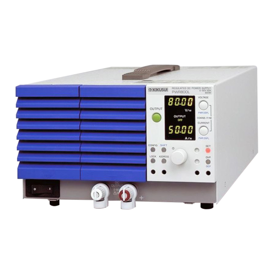
Front panel Display V/ V/ CV CV OUTPUT OUTPUT A/ A/ PWR400L example... - Page 15 Name Description +SHIFT OUTPUT Output on/off switch. p.4-6 Air inlet (louver) Air inlet for internal cooling. A dust filter is built in. p.8-3 SHIFT Switch for calling up the functions marked in blue p.vi characters. CONFIG Switch for setting various conditions concerning p.4-23 the operation.
-
Page 16: Rear Panel
Rear panel 400 W type example 1600 W type Name Description Connector for external control, series oper- p.5-2 ation, and parallel operation. TP-BUS Remote control connector – Serial number The serial number of the PWR. – Chassis terminal A terminal used to ground the output. p.3-7 Sensing terminal A terminal used to connect the sensing... -
Page 17: Chapter 1 General Description
General Description This chapter gives an overview and describes the fea- tures. -
Page 18: About This Manual
This operation manual describes the fol- lowing models. Table 1-1 PWR series types L Type M Type H Type (80 V) (320 V) (650 V) 400 W type PWR400L PWR400M PWR400H 800 W type PWR800L PWR800M PWR800H 1600 W type PWR1600L PWR1600M PWR1600H Applicable firmware version of the PWR This manual applies to PWRs with firmware version 1.2x. -
Page 19: Product Overview
Equipped with a digital remote control function through TP- BUS (Twist Pair-BUS) communication. (The total length of TP-BUS is 200 m.) By combining with Kikusui’s PIA4800 Series Power Supply Controller, systemization for applications such as an auto- matic tester is possible. -
Page 20: Options
Options Below are options available for the PWR series. For details on the options, contact your Kikusui agent or distributor. Rack Table 1-2 Rack mounting options Applicable Product Model Notes Model Inch rack KRA3 EIA standard Rack mount 400 W type... - Page 21 Unit: inch KRB3-TOS Unit: mm KRB150-TOS Fig. 1-2 Rack mount bracket Analog Remote Control Connector Kit (OP01-PAS) A kit for connecting to the J1 connector on the rear panel. Component Quantity Socket 1 pc. Pins 10 pcs. Protection 1 set cover Chassis con- 1 pc.
- Page 22 Handle (for the 400 W type) (CH01-PWR) A carrying handle that can be attached to the top panel of the 400 W type. Fig. 1-4 Handle...
-
Page 23: Chapter 2 Installation And Preparation
Installation and Preparation This chapter describes the procedures of unpacking and preparation of the PWR before use. -
Page 24: Checking The Package Contents
If any of the accessories are damaged or missing, contact your Kikusui agent or distributor. We recommend that all packing materials be saved, in case the product needs to be transported at a later date. -
Page 25: Precautions Concerning Installation
1 set 1 pc. [Q1-500-077] [84-61-5102] OUTPUT terminal cover TP-BUS connector [M1-100-011] 2 pcs. [M5-101-007] [M3-112-026] [M4-100-007] 2 sets M4 output terminal screws M8 output terminal screws 1pc. [Z1-003-902] Operation Manual Fig. 2-2 Accessories common to all types Precautions Concerning Installation This product cannot be used while it is on its side. -
Page 26: Precautions Concerning Installation Location
However, operation in such environments may be possible through alteration. If you want to use the PWR in such envi- ronments, consult your Kikusui agent or distributor. Do not place the product in a dusty location. Accumulation of dust may lead to electric shock or fire. -
Page 27: Precautions To Be Taken When Moving The Product
Do not use the product where ventilation is poor. The product employs a forced air cooling system. Air is taken in from air inlet located on panels other than the rear panel and exhausted from the air outlet on the rear panel. Secure adequate space around the product to prevent fire caused by accumulation of heat. -
Page 28: Rack Mounting The Product
When transporting the product, be sure to use the orig- inal packing materials. Otherwise, damage may result from vibrations or from the product falling during transportation. Be sure to include this manual. Rack Mounting the Product Remove the feet and handle before attaching the product to the rack mount frame. - Page 29 1600 W type Side feet Pins Rivets Handle Brackets Covers M4 flat head screws Bottom feet (M4×0.7×8) Rivets Screw pins Hook the pin with a flat-blade screw driver and remove it. Fig. 2-4 Removing the handle and feet (1600 W type) Removing the handle and feet The handle is an option for the 400 W type.
-
Page 30: Connecting The Power Cord
Connecting the Power Cord The power cord provided with the PWR varies depending on the output capacity type. For the procedure to connect the power cord, see the respective section for each type. This product is designed as an equipment of IEC Overvoltage Category II (energy-consuming equipment supplied from the fixed installation). -
Page 31: 400 W And 800 W Types
• Have a qualified engineer select the appropriate power cord. If obtaining a power cord is difficult, consult your Kikusui agent or distributor. • The power cord with a three-prong plug is used to discon- nect the PWR from the AC line in an emergency. Con-... -
Page 32: 1600 W Type
1600 W type The power cord that is included with the 1600 W type can be used on either a 100-V or 200-V system. WARNING Possible electric shock. • Turn off the circuit breaker of switchboard before connecting the cord. Possible Fire. - Page 33 ■ Circuit breaker of switchboard requirement • Rated current: 30 A (The circuit breaker of which the rated current is more than 30 A is disabled for safety.) • Dedicate the circuit breaker for the PWR. • Keep the switchboard easily accessible at any time. •...
- Page 34 Procedure to connect the power cord (GND) N: White or blue (GND): Green or green/yellow AC INPUT terminal block L: Black or brown Fastening plate Cable clamp Fix the covered part of the power Fastening plate cord with the fastening plate. Fig.
-
Page 35: Turning The Power On
Turning the Power On Turn the power on without the load connected. CAUTION • The CONFIG parameters can be set so that the out- put is automatically turned on when the POWER switch is turned on. When this function is enabled, the PWR powers up with the output turned on even if the output was off when the PWR was turned off the last time. -
Page 36: Inrush Current
If the POWER switch is turned on for the first time after pur- chasing the PWR, the PWR starts up in a factory default condi- Page 4-32 tion. For all other cases, the PWR starts up using the settings that existed when the POWER switch was turned off the last time. -
Page 37: Chapter 3 Connecting The Load
Connecting the Load This chapter describes the consideration to be given to the load, explains how to connect the load wires, and explains how to connect to the output terminals. -
Page 38: Load Considerations
Load Considerations Note that the output will become unstable if the following types of loads are connected. • Load current with peaks and pulse-shaped load current. • Load that generates reverse current to the power supply. • Load with accumulated energy. Load current with peaks and pulse-shaped load current The PWR indicates mean values. - Page 39 Load that generates reverse current to the power supply The PWR cannot absorb reverse current from the load. There- fore, if a regenerative load (such as an inverter, converter, or transformer) is connected, the output voltage increases and becomes unstable. For these types of loads, connect a resistor (R ) as shown in Fig 3-3 to bypass the reverse current.
- Page 40 Load with accumulated energy Connecting a load with accumulated energy, such as a battery, to the PWR may cause current to flow from the load to the internal circuit of the PWR. This current may damage the PWR or degrade the service life of the load. For this type of loads, connect a reverse-current-prevention diode (D ) between the PWR and the load in series as shown...
-
Page 41: Load Wire
However, installing the + (pos.) and - (neg.) output wires side by side or bundling them together is more effective against unwanted noise. The Kikusui-recommended cur-... - Page 42 Table 3-1 Nominal cross-sectional area of wires and allowable currents Nominal (Reference Current Rec- Allowable Cross-Sec- Cross-Sec- ommended Current tional Area tional Area) by Kikusui (Ta = 30•C) (2.08) (3.31) (5.26) (8.37) (13.3) (21.15) (33.62) (42.41) (53.49) (67.43) (85.01) (107.2) Excerpts from Japanese laws related to electrical equip- ment.
-
Page 43: Connecting To The Output Terminal
Connecting to the Output Terminal 3.3.1 Connecting to the Output Terminal on the Rear Panel WARNING • Possible electric shock. Be sure to turn the POWER switch off before touching the output terminal on the rear panel. Be sure to attach the OUTPUT terminal cover after wiring the load. - Page 44 Connect the load wire to the output terminal on the rear panel. Fig 3-6 If you are using M8 screws, pay attention to the direction of the screws. Connection using M4 screws Screw (M3 + spring washer) Crimping terminal Connection using M8 screws Screw (M8) Crimp terminal Spring washer...
-
Page 45: Attaching The Output Terminal Cover
Attaching the OUTPUT terminal cover There are two types of OUTPUT terminal covers: bottom cover and top cover. Insert the hook of the bottom cover into the hole located above and to the left of the output terminal. The bottom cover is the one without screws. Align the hook of the bottom cover to the groove located to the side of the output terminal. -
Page 46: Connection To The Output Terminal On The Front Panel
• Possible overheating or fire. Do not supply cur- rents that exceed 30 A from the output terminal on the front panel on the L type. If the front output terminal cover is damaged or lost, contact Kikusui distributor/agent. [P1-000-408] Fig. 3-8 Front output terminal cover 3-10... - Page 47 Turn the POWER switch off. Attach crimping terminals to the load wires. Remove the knob and connect the load wire to the output terminal on the front panel. Attach the knob. Attach so that the wire passes Knob through this section. Crimping terminal Fig.
- Page 48 3-12...
-
Page 49: Chapter 4 Basic Operation
Basic Operation This chapter describes how to turn on/off the output and the basic operations that you can carry out from the front panel. -
Page 50: Measured Value Display And Setting Display
Measured Value Display and Setting Display The voltage and current displays have the following three states. • Measured value display • Setting display In addition to the voltage and current displays, OVP/OCP set- ting, system configuration, and node address displays are avail- able. - Page 51 The output power is displayed when the output is on. You can change the voltage or current while viewing the actual output power. The output power is a value calculated from the mea- sured output voltage and measured output current. The unit (V/ or A/ ) to the right of the LED illuminates when...
-
Page 52: Panel Control
Panel control For measured value display, setting display, and OVP/OCP setting value display Turn the setting knob to change the highlighted digit or higher digits on the panel display. The value can be changed regardless of whether the OUTPUT is on or off. To set the current to a value greater than 105 % of the rated out- put current in the extended operating area (L type only), turn Page 4-11... - Page 53 You can also press the setting knob to switch between coarse and fine. The highlighted digit varies depending on the model. See Table 4-1. The underlined digit is highlighted. Table 4-1 Highlighted digit Model Display Coarse Fine Voltmeter/ PWR400L 00.00 00.00 Ammeter Voltmeter/ PWR800L 00.00 00.00 Ammeter Voltmeter 00.00 00.00...
-
Page 54: Output Operation
Output Operation The OUTPUT switch is a toggle switch. When the output is on, the OUTPUT ON indicator on the display illuminates; when the output is off, the OUTPUT OFF indicator illuminates. When the output is on, the present setting is output. If you change the setting while the output is on, the change is applied to the output. -
Page 55: Description Of Operation
Description of Operation The PWR is a constant voltage/current regulated DC power supply that is capable of delivering voltages and currents in a wide operating range within the rated output power. Fig. 4-6 shows the operating area of the 400 W type. in the figure indicates the rated operating area, and indi- cates the extended operating area. -
Page 56: Constant Voltage (Cv) And Constant Current (Cc) Pow
The output current must be derated with respect to the tempera- ture at ambient temperatures greater than or equal to 45 ºC (30 ºC when operating in the extended operating area) on the L type º and 40 C on the M/H type. Output current [%] Extended operating L type... - Page 57 >Rc = Rc Vmax Crossover point = CV mode area = CC mode area Vs = Preset voltage < Rc Is = Preset current Rc = Vs/Is (Ohm's Law) RL = Load resistance Vmax = Maximum preset voltage Imax Imax = Maximum preset current Output current Iout Fig.
-
Page 58: Crossover Point
For loads that generate transient surge voltage, preset voltage Vs must be set so that the surge voltage does not reach the volt- age limit. ■ Crossover point CV mode and CC mode switch automatically according to the changes in the load. The point at which the mode switches is called the crossover point. -
Page 59: Extended Operating Area (L Type Only)
Rated output power line Rated output current Continuous extended operating area Intermittent extended operating area Rated operating area Maximum output current Extended operating area PWR400L 20 25 30 PWR800L 10 20 40 50 60 PWR1600L 20 40 80 100 120 Output current [A] Fig. - Page 60 The ALM LED blinks when operating in the extended operat- ing area. In this case, the ALM signal is not output. Output current [%] Intermittent extended Extended operating area operating area Continuous extended operating area (Rated output current) Rated operating area Ambient temperature [°C] Fig.
-
Page 61: Using The Pwr As A Cv Or Cc Power Supply
Using the PWR as a CV or CC Power Supply (Setting the Output Voltage and Current) When using the PWR as a constant voltage power supply, the preset current is the limit that can flow through the load. When using the PWR as a constant current power supply, the preset voltage is the limit that can be applied to the load. - Page 62 You can change the actual output voltage or output current while viewing the value even with the output turned on by car- rying out step 5 and step 6 . You can also change the actual output voltage or output current while viewing the power.
-
Page 63: Protection Function And Alarm
Protection Function and Alarm The PWR is equipped with the following protection function. • Overvoltage protection (OVP) • Overcurrent protection (OCP) • Overpower protection (OPP) • Overheat protection (OHP) • Shutdown (SHUT) • Power limit (POWER LIMIT) 4.6.1 Alarm occurrence and release Alarm occurrence When a protection function activates, the PWR behaves as follows: V/ V/... -
Page 64: Alarm Signal
If you cannot clear the alarm even when all of the causes of the alarm are eliminated, the PWR may have malfunctioned. If this happens, stop using the PWR and contact your Kikusui agent or distributor. ■ When the breaker trips (when the POWER switch turns off) After eliminating the cause of the alarm, turn on the POWER switch. -
Page 65: Overvoltage Protection (Ovp) And Overcurrent Protec
4.6.2 Overvoltage protection (OVP) and overcurrent protection (OCP) The overvoltage protection (OVP) and overcurrent protection (OCP) functions activate under the following conditions. Conditions in which the OVP is activated • When the output terminal voltage exceeds the specified voltage (OVP trip point). •... - Page 66 Table 4-4 OCP trip point range OCP Trip Point OCP Trip Point Model Model Range Range PWR400L 2.50 A to 44.00 A PWR400M 0.625 A to 6.875 A PWR800L 5.00 A to 88.00 A PWR800M 1.25 A to 13.75 A PWR1600L 10.00 A to 176.0 A...
- Page 67 ■ Setting the OCP trip point Press the OCP (SHIFT+OVP) switch. The ammeter shows the setting, and the voltmeter shows “OCP.” Use the CURRENT switch and setting knob to set the OCP trip point. Page 4-4 If the output is on and the OCP trip point is set lower than the preset output current, the OCP trips, and the output turns off or the POWER switch turns off.
- Page 68 Turn the setting knob slowly clockwise, and check that the output turns off or the breaker trips when the output voltage exceeds the preset OVP trip point. Turn the POWER switch off. Short the output terminal. Turn the POWER switch on. Set the output voltage to a value less than the OVP trip point.
-
Page 69: Other Protection Functions
4.6.3 Other Protection Functions Overpower protection (OPP) This function is activated when a condition that exceeds approximately 110 % of the rated output power persists for a certain period (approximately 2 seconds) such as due to a tran- sient load change. You can select whether to trip the breaker (C-8: 0/1) when the OPP function activates. - Page 70 Shutdown (SHUT) Shutdown is not activated as a result of the PWR detecting an error. It is a function used to turn off the output by applying an Page 5-21 external signal to the J1 connector on the rear panel when an abnormal condition occurs.
-
Page 71: Config Settings
CONFIG Settings CONFIG settings are used to set the system configuration of the PWR. You can set or display the parameters in Table 4-7 in the CONFIG settings. Parameter number V/ V/ CV CV OUTPUT OUTPUT Preset number A/ A/ Fig. - Page 72 Setting the system configuration Set the system configuration of the PWR. While holding down the CONFIG switch, turn on the POWER switch. Keep holding down the CONFIG switch until the voltmeter dis- plays “ConF.” The CONFIG switch illuminates, and a parameter number highlighted. Turn the setting knob to select the parameter number you want to set.
-
Page 73: Config Parameter Details
CONFIG parameter details The details of the CONFIG parameters are described below. C-1 CV control source setting Selects the constant voltage control mode. Page 5-10 Preset Description Page 5-12 Number Panel control (Factory default) External voltage control Ω → External resistance control 10 k MAX OUT Ω... - Page 74 C-4 Output status setting at power-on Sets the output state when the POWER switch is turned on. This setting is invalid when the output is turned off using an Page 4-29 external contact. Preset Description Number Output is off at power-on. (Factory default) Output is on at power-on.
- Page 75 C-7 Termination setting during remote control Turns on/off the termination for remote control. Preset Description Number Termination: Off (Factory default) Termination: On C-8 Breaker trip setting when the protection function trips Sets whether to trip the breaker (turn the POWER switch off) when the OVP (overvoltage protection), OCP (overcurrent pro- Page 5-21 tection), OPP (overpower protection) is activated or when an...
-
Page 76: Lock Function
Lock Function The PWR has a lock function that prevents the settings from being changed inadvertently. When the panel lock is enabled (LOCK switch illuminates), the switches on the front panel (excluding the OUTPUT switch) and the setting knob are disabled. Set all the required parameters such as the output voltage and output current. -
Page 77: Remote Sensing Function
Remote Sensing Function The remote sensing function is used to reduce the influence of voltage drops due to the load wire resistance and stabilize the output voltage across the load. The remote sensing function of the PWR can compensate up to approximately 0.6 V for a single line. - Page 78 After you are done using the remote sensing function, remove the sensing wires, and be sure to turn off remote sensing in the Page 4-24 CONFIG settings (C-3: 0). Output terminal Load – – Connect an electrolytic capacitor as necessary. Sensing terminal 2-core shielded wire Fig.
- Page 79 ■ Electrolytic capacitor connected at the load end If the inductance in the wire is large, the following symptoms may appear. • Oscillation If the wiring cable to a load is long, the phase shift caused by the inductance and capacitance of the wiring becomes non- negligible, thereby causing oscillation.
-
Page 80: 4.10 Factory Default Settings
4.10 Factory Default Settings Turning ON the POWER switch while holding down the SHIFT switch initializes the settings to factory default (exclud- ing the node address setting). If you want to reset all the settings to factory default, set the node address to 5 after carrying out the initialization procedure above. -
Page 81: Chapter 5 External Control
External Control External Control This chapter describes external control and external mon- itoring using the J1 connector. -
Page 82: Overview Of External Control
At the factory shipment, the protection socket is attached to the J1 connector. Keep this protection socket and be sure to attach when the J1 connector is not used. If the protection socket is damaged or lost, contact Kikusui distributor/agent. [84-49-0110] Fig. 5-1... -
Page 83: J1 Connector Arrangement
For information on how to obtain the tools and parts, contact your Kikusui agent or distributor. An optional OP01-PAS Analog Remote Control Connector Kit is available for making the connection. Fig. 5-2 OP01-PAS [84500] Table 5-1 Connector parts by Omron needed to... - Page 84 Table 5-2 J1 connector arrangement Signal Name Description An analog signal common for pins 3 to 7. Connected to the negative electrode (-S) of the sensing A COM input when remote sensing is used; connected to - (neg.) output when remote sensing is not used. Connected to the negative electrode (-S) of the sensing D COM input when remote sensing is used;...
- Page 85 Signal Name Description Correction signal input terminal during master-slave COMP IN parallel operation Positive electrode output terminal to the next device NEXT PRL OUT+ during master-slave parallel operation. Correction signal output terminal to the next device dur- NEXT COMP OUT ing master-slave parallel operation.
-
Page 86: Output Terminal Insulation
Output Terminal Insulation Note the following points and insulate the output terminals. WARNING • Possible electric shock. For safety reasons, even if the output terminal is grounded, make sure the insulation capacity of the output termi- nal (including the sensing terminal) is greater than the isolation voltage of the PWR. -
Page 87: When The Output Terminal Is Not Grounded (Floating)
5.3.1 When the Output Terminal Is Not Grounded (Floating) The output terminal of the PWR is isolated from the protective conductor terminal. By connecting the GND wire of the power cord to the ground terminal of the switchboard, the chassis of the PWR is set to ground potential as shown in Fig. -
Page 88: When The Output Terminal Is Grounded
5.3.2 When the Output Terminal Is Grounded If the positive output terminal is connected to the chassis termi- nal, the terminal is at ground potential as shown in Fig. 5-5. Therefore, the wires and load that are connected to the output terminal (including the sensing terminal) only require an insu- lation capacity that is greater than the maximum output voltage of the PWR with respect to the chassis. - Page 89 Precautions to be taken when using the external voltage (Vext) Be sure that the output is not shorted as shown in Fig. 5-6 and Fig. 5-7. CAUTION The signal wire may burn out. • Leave the Vext output floating. • If you are connecting the shield at the Vext end, do not connect the shield to the output terminal of the PWR.
-
Page 90: Output Voltage Control
Output Voltage Control This section explains the method used to control the output voltage using an external voltage (Vext) in the range 0 V to approx. 10 V or an external resistor (Rext) in the range 0 kΩ to approx. 10 kΩ. If no load is connected, it takes a long time for the output voltage to fall. - Page 91 Connecting the external voltage (Vext) Use a low-noise and stable voltage source for Vext. The noise in Vext is multiplied by the amplification factor of the PWR and appears at the output. Thus, the output ripple noise may not meet the PWR’s specifications. To minimize the influence of noise on the output, use a two- core shielded wire or a twisted-pair wire to connect the control terminals and Vext.
-
Page 92: External Resistance (Rext) Control
5.4.2 External Resistance (Rext) Control To control the output voltage using Rext, select the CV control source in the CONFIG settings from the following two modes. Page 4-23 Ω → • External resistance control 10 k MAX OUT (C-1: 2) The output voltage (Eo) varies in the range of 0 to the rated output voltage (Ertg) by setting the external resistance (Rext) in the range of 0 kΩ... - Page 93 External resistance (Rext) connection For Rext, use a 1/2 W or larger metal film or wire-wound type resistor with good temperature coefficient and small aging effect. To minimize the influence of noise on the output, use a two- core shielded wire or a twisted-pair wire to connect the control terminals and Rext.
-
Page 94: Output Current Control
Output Current Control This section explains the method used to control the output cur- rent using an external voltage (Vext) in the range 0 V to approx. 10 V or an external resistor (Rext) in the range 0 kΩ to approx. 10 kΩ... - Page 95 External voltage source (Vext) connection Use a low-noise and stable voltage source for Vext. The noise in Vext is multiplied by the amplification factor of the PWR and appears at the PWR output. Thus, the output ripple noise may not meet the PWR’s specifications. To minimize the influence of noise on the output, use a two- core shielded wire or a twisted-pair wire to connect the control terminals and Vext.
-
Page 96: External Resistance (Rext) Control
5.5.2 External Resistance (Rext) Control To control the constant current using Rext, select the CC con- trol source in the CONFIG settings from the following two Page 4-23 modes. Ω → • External resistance control 10 k MAX OUT (C-2: 2) The output current (Io) varies in the range of 0 to the maxi- mum output current (Imax) on the L type by setting the external resistance (Rext) in the range of 0 kΩ... - Page 97 External resistance (Rext) connection For Rext, use a 1/2 W or larger metal film or wire-wound type resistor with good temperature coefficient and small aging effect. To minimize the influence of noise on the output, use a two- core shielded wire or a twisted-pair wire to connect the control terminals and Rext.
-
Page 98: Controlling The Output On/Off
Controlling the Output On/Off This section explains the method used to control the on/off of the output by using an external contact. WARNING Possible electric shock. • The insulation of the external contact (S) and the connected wire should be greater than the isola- tion voltage of the PWR. - Page 99 If the output is set to off using an external contact, the OUT- PUT switch on the front panel is invalid. If you are not control- ling the output using an external contact, turn the output on by setting the external control logic setting of output on/off in the CONFIG settings to high (C-6: 0).
- Page 100 External contact connection Pins 2 and 3 of the J1 connector are used. The release voltage across pins 2 and 3 is approx. 5 V ± 5 % maximum, and the short circuit current is approx. 500 µA ± 5 % maximum.
-
Page 101: Shutdown Control
Shutdown Control This section explains the method used to trip the breaker (turn the POWER switch off) or turn the output off using external contact. WARNING Possible electric shock. • The insulation of the external contact (S) and the connected cable should be greater than the iso- lation voltage of the PWR. - Page 102 Shutdown control connection Pins 2 and 10 of the J1 connector are used. The release voltage across pins 2 and 10 is approx. 5 V ± 5 % maximum, and the short circuit current is approx. 500 µA ± 5 % maximum.
-
Page 103: External Monitoring
External Monitoring External monitoring of the output voltage and output current The J1 connector consists of monitor outputs for output voltage and output current. Table 5-3 Monitor output of output voltage and output current Signal Description Name Common for remote control input. A COM Common for output monitor. -
Page 104: External Monitoring Of The Operating Status
External monitoring of the operating status The J1 connector consists of status outputs that is used to exter- nally monitor the operating status of the PWR. The following five status outputs are available. The outputs are open collector outputs of photocouplers; they are insulated from the internal circuits of the PWR. - Page 105 Parallel Series Operation This chapter describes the functions of the master-slave parallel/serial operation and the connection, setup, and operation procedures.
-
Page 106: Master-Slave Series Operation (L Type Only)
In master-slave operation, one of the PWRs is made the master unit and connected to the same model as slave units. The master unit is used to control the entire system. During series/parallel operation, the setting accuracy of master and slave units is the same as that of single units. - Page 107 Remote sensing Cannot be used. External control Can be used only on the master unit. Chap5 External monitoring Page 5-23 WARNING • Be careful of short-circuits and electric shock while monitoring signals. The common electric potential of the output voltage and output cur- rent monitor signals during master-slave series operation are different between the master unit and slave unit.
-
Page 108: Connection (Series Operation)
You can select whether to trip the breaker (C-8: 0/1) when an alarm is detected. Page 4-27 ■ Clearing the alarm Turn off the POWER switch of the slave unit first followed by the master unit. After removing all the causes of alarm, turn on Page 4-16 the POWER of the master unit first followed by the slave unit. -
Page 109: Load Connection (Series Operation)
Load connection (series operation) Connect the load as shown below. WARNING • Possible electric shock. Be sure to turn the POWER switch off before touching the output terminal. Be sure to attach the OUTPUT terminal cover after wiring the load. Load or relay terminal block Output terminal Chassis terminal... -
Page 110: Setup (Series Operation)
6.1.3 Setup (Series Operation) ■ Setting the overvoltage protection (OVP) and over- current protection (OCP) Set the OVP and OCP on both the master unit and slave unit. The OVP is set to one-half the voltage to be protected to the Page 4-17 master unit and slave unit. -
Page 111: Procedure (Series Operation)
6.1.4 Procedure (Series Operation) The power supplies may not operate properly if the procedure is not followed. Turning the power on Turn on the POWER switch on the master unit. Turn on the POWER switch on the slave unit. Carry out normal operations on the master unit. The panel operation on the slave units is disabled. -
Page 112: Master-Slave Parallel Operation
Master-Slave Parallel Operation The output current can be expanded using master-slave parallel operation (maximum output current: the rated output current of a unit × number of units connected in parallel). Maximum number of units that can be connected is five including the master. - Page 113 External monitoring Page 5-23 CAUTION • Do not connect the common wires of the master and slave monitors outside the PAT. If the wire connect- ing the load comes loose, the common wire will break. • External monitoring of output voltage (V MON) Can be monitored on the master unit.
- Page 114 Alarms If an alarm is detected, the units behave as follows: • Slave unit An alarm is activated independently. Then, the output is turned off, or the breaker is tripped. • Master unit If an alarm is detected on the master unit, the alarm on the slave unit is also activated, and the output of the entire sys- tem is turned off or the breaker is tripped.
-
Page 115: Connection (Parallel Operation)
6.2.2 Connection (Parallel Operation) Up to 5 units can be connected including the master unit. Connecting the signal wires (parallel operation) An example in which two slave units are connected is given below. The connector needed to connect the J1 connector is not pro- vided. -
Page 116: Connecting The Load (Parallel Operation)
Connecting the load (parallel operation) Connect the load as shown below. WARNING • Possible electric shock. Be sure to turn the POWER switch off before touching the output terminal. Be sure to attach the OUTPUT terminal cover after wiring the load. CAUTION •... - Page 117 Turn off the POWER switches on all PWR Series power supply units to be connected in parallel. Remove the OUTPUT terminal cover. Page 3-9 Connect the output terminals (+ or –) of the master and slave units to the chassis terminal. Use the same polarities for the output terminals of the master and slave units.
-
Page 118: Setup (Parallel Operation)
6.2.3 Setup (Parallel Operation) ■ Setting the overvoltage protection (OVP) and over- current protection (OCP) Set the OVP and OCP on both the master unit and slave units. Set the value equal to the current to be protected divided by the Page 4-17 number of units connected in parallel for OCP. -
Page 119: Procedure (Parallel Operation)
6.2.4 Procedure (Parallel Operation) The power supplies may not operate properly if the procedure is not followed. Turning the power on Turn on the POWER switch on the master unit. Turn on the POWER switch on the slave units. Carry out normal operations on the master unit. The panel operation on the slave units is disabled. - Page 120 6-16...
-
Page 121: Chapter 7 Remote Control
Remote Control Remote Control This chapter gives an overview of the remote control using the TP-BUS. For details on the Power Supply Con- troller, see the operation manual of the respective prod- uct. For connection to a Power Supply Controller and device messaages, refer to the “Connecting &... -
Page 122: Remote Control Overview
The list of messages and connection of power supply of Connecting & programming guide is provided in a PDF file. Adobe Reader 6.0 or later is required to view the file. The latest version of the “Connecting & Programming Guide” can be downloaded from Web site (http://www.kikusui.co.jp/ en/download/). -
Page 123: Chapter 8 Maintenance
Maintenance This chapter describes maintenance and inspection of the PWR. -
Page 124: Inspection
WARNING • Tears in the insulation coating of the power cord may cause electric shock or fire. If a tear is found, stop using it immediately. To purchase accessories or options, contact your Kikusui agent or distributor. 8.1.1 Cleaning WARNING •... -
Page 125: Cleaning The Dust Filter
Cleaning the dust filter Dust filters are furnished on the inside of the louver and at the bottom of the operation panel. Periodically clean the filter to prevent clogging. CAUTION • Clogged dust filters hinder the cooling of the inside of the unit and can cause malfunction and shorten- ing of the service life. - Page 126 Attach the dust filter to the louver. Attach it so that the dust filter fits inside the hooks of the louver. Dust filter Hook Louver Fig. 8-2 Dust filter attachment Align and set the hooks of the louver to the panel grooves.
-
Page 127: Calibration
We recommend periodic calibration to maintain the perfor- mance over an extended period. For calibration, contact your Kikusui agent or distributor. If you are going to calibrate the PWR yourself, follow the proce- dures below. All of the calibration items of the PWR are described. -
Page 128: Voltage Calibration
Environment Perform calibration under the following environment. • Temperature: 23 ºC ± 5 ºC • Relative humidity: 80 %rh or less To minimize the calibration error due to initial drift, warm up the PWR for at least 30 minutes before calibration. Warm up the DVM and shunt for their appropriate time. - Page 129 Calibration of the output voltage offset and full scale Turn the POWER switch off, and connect a DVM to the output terminal. While holding down the SET switch, turn on the POWER switch. The ammeter shows “CAL.” Hold down the SET switch until “CAL”...
- Page 130 Calibration of the OVP (overvoltage protection) offset and full scale Calibrate the OVP after completing the calibration of the volt- age. To continue with the OVP calibration after the voltage cal- ibration, start from step 3 . Turn the POWER switch off, and connect a DVM to the output terminal.
-
Page 131: Current Calibration
8.2.3 Current Calibration Calibration mode indication CAL: Current system OCP: OCP Calibration status indication 0: Calibration start V/ V/ 1: Offset adjustment procedure complete CV CV 2: Full scale adjustment procedure complete OUTPUT OUTPUT Calibration selection indication 3: Offset and full scale adjustment OF: Offset procedure complete FS: Full scale... - Page 132 Calibration of the output current offset and full scale Turn the POWER switch off, and connect a shunt and a DVM to the output terminal. While holding down the SET switch, turn on the POWER switch. The voltmeter shows “CAL.” Hold down the SET switch until “CAL”...
- Page 133 Calibration of the OCP (overcurrent protection) offset and full scale Calibrate the OCP after completing the calibration of the cur- rent. To continue with the OCP calibration after the current cal- ibration, start from step 3 . Turn the POWER switch off, and connect a shunt and a DVM to the output terminal.
-
Page 134: Troubleshooting
If none of the items apply to your case, we recommend that you initialize the PWR to factory default condition. If the remedy Page 4-32 does not correct the problem, contact your Kikusui agent or dis- tributor. ■ The power does not turn on. - Page 135 ■ The ALM indicator illuminates when the OUTPUT switch is turned on. Check Item Cause and Remedy Page Is the OVP trip point set less Set the OVP trip point to a voltage greater than or equal to the output than or equal to the output voltage.
- Page 136 ■ The ALM indicator blinks. Check Item Cause and Remedy Page Did the load resistance The POWER LIMIT function was activated change? as a result of the change in the load resis- 4-22 tance. This is not a malfunction. Are you using the PWR in The ALM indicator blinks when operating the extended operating in the extended operating area.
- Page 137 ■ The output is unstable. Check Item Cause and Remedy Page Is the operation mode Change the setting (output voltage or out- switching from CV to CC or put current) that is limiting the output to a CC to CV? value greater than the present setting.
- Page 138 ■ The PWR cannot be controlled remotely. Check Item Cause and Remedy Page Is the CV/CC control source Set it to panel control (C-1: 0 and C-2: 0). 4-23 set to external control? 8-16...
-
Page 139: Chapter 9 Specifications
Specifications This chapter lists the specifications. - Page 140 Unless specified otherwise, the specifications are for the fol- lowing settings and conditions. • The load is a pure resistance. • The warm-up time is 30 minutes (with current flowing). • After warm-up is complete, the PWR must be calibrated correctly according to the procedures given in the operation manual in a 23 ºC ±...
-
Page 141: Common Specifications
Common specifications Common Specifications AC input 100 Vac to 240 Vac. Nominal input rating 50 Hz to 60 Hz, single phase. 85 Vac to 250 Vac. Input voltage range Hold-up time for power interruption 10 ms (at 50 % load). (MIN) 5 ms (at rated load). - Page 142 Common Specifications Display function Voltmeter Maximu L type 99.99 (fixed decimal point). m display M/H type 999.9 (fixed decimal point). Display error ±(0.2 % of rdng + 5 digits) at 23 ºC ± 5 ºC. Ammeter Maximu Models with a 9.999 (fixed decimal point).
- Page 143 Common Specifications Control function TP-BUS Digital control Directly controllable from the PIA4810 or PIA4830. External *12 , *13 0 % to 100 % of the rated output voltage in the EXT-V CV CONT analog range of 0 V to 10 V. control EXT-R Normal...
- Page 144 Common Specifications General Environm Operating conditions Indoor use, Overvoltage Category II. ental Operating 0 ºC to +50 ºC (32 ºF to 122 ºF) conditions With output current derating. temperature L type: 45 ºC (113 ºF) or higher M/H type: 40 ºC (104 ºF) or higher Operating humidity 20 %rh to 85 %rh (no condensation).
- Page 145 Common Specifications General (cont.) Accessories Operation Manual 1 pc. Power 400 W SVT3 18AWG: 1 pc. type with 3 P plug and connector. cord cable length 2.4 m. 800 W SJT3 14AWG: 1 pc. type with 3 P plug and connector. cable length 3 m.
-
Page 146: Model-Specific Specifications (L Type)
Model-specific specifications (L type) PWR400L PWR800L PWR1600L Output specifications Rating 400.0 W 800.0 W 1600 W Rated output voltage 80.00 V 80.00 V 80.00 V Rated output current 25.00 A 50.00 A 100.0 A Voltage Maximum preset voltage (typ) 105 % of rtg *2 , *3 0.1 % of rtg + 10 mV... - Page 147 Output voltage fluctuation when the output voltage is set to the rated output voltage and the load is changed from rated load to no load (open load) under constant voltage operation. The time it takes for the output voltage fluctuation to recover from outside 0.1 % + 10 mV of the output voltage setting to within 0.1 % + 10 mV when the output voltage is set to the rated output voltage and the output current is changed from 100 % to 50 % or 50 % to 100 % of the maximum output current at the rated...
- Page 148 PWR400L PWR800L PWR1600L Input specifications 100 VAC 6.5 A 13.0 A 26.0 A Current (MAX) 200 VAC 3.3 A 6.5 A 13.0 A 35 Apeak 70 Apeak 140 Apeak Inrush current (MAX) 650 VA 1 300 VA 2 600 VA Power (MAX) 0.980...
- Page 149 9-11...
-
Page 150: Model-Specific Specifications (M Type)
Model-specific Specifications (M type) PWR400M PWR800M PWR1600M Output specifications Rating 400.0 W 800.0 W 1600 W Rated output voltage 320.0 V 320.0 V 320.0 V Rated output current 6.250 A 12.50 A 25.000 A Voltage Maximum preset voltage (typ) 105 % of rtg *2 , *3 0.1 % of rtg + 10 mV Setting accuracy... - Page 151 PWR400M PWR800M PWR1600M General (cont.) Approx. 5 kg Approx. 8 kg Approx. 15 kg Weight (11.02 lbs) (17.64 lbs) (33.07 lbs) Dimensions See Outline Drawing. The maximum preset voltage is provided for establishing a rated output voltage setting. It does not guarantee power supply to the load exceeding the rated output voltage.
-
Page 152: Model-Specific Specifications (H Type)
Model-specific specifications (H type) PWR400H PWR800H PWR1600H Output specifications Rating 400.0 W 800.0 W 1600 W Rated output voltage 650.0 V 650.0 V 650.0 V Rated output current 2.000 A 4.000 A 8.000 A Voltage Maximum preset voltage (typ) 105 % of rtg *2 , *3 0.1 % of rtg + 10 mV Setting accuracy... - Page 153 PWR400H PWR800H PWR1600H General (cont.) Approx. 5 kg Approx. 8 kg Approx. 15 kg Weight (11.02 lbs) (17.64 lbs) (33.07 lbs) Dimensions See Outline Drawing. The maximum preset voltage is provided for establishing a rated output voltage setting. It does not guarantee power supply to the load exceeding the rated output voltage.
-
Page 154: Outline Drawing
Outline Drawing 4-M3s (insert up to 6 mm (0.24 inch)) 78 (3.07) 257 (10.12) 70 (2.76) 275 (10.83) 4-Ø5 (Ø0.2) (foot attachment hole) MAX20 MAX470 (18.50) (0.79) 400 (15.75) 106.5 (4.19) Unit: mm (inch) Fig. 9-1 400 W type outline drawing 9-16... - Page 155 4-M3s (insert up 78 (3.07) 267 (10.51) to 6 mm (0.24 inch)) 275 (10.83) 4-Ø5 (Ø0.2) 70 (2.76) (foot attachment hole) MAX470 (18.50) 214 (8.43) MAX20 400 (15.75) (0.79) Unit: mm (inch) Fig. 9-2 800 W type outline drawing 9-17...
- Page 156 4-M3s (insert up to 6 mm (0.24 inch)) 62 (2.44) 283 (11.14) 4-Ø5 (Ø0.2) 275 (10.83) (foot attachment 70 (2.76) hole) MAX20 MAX470 (18.50) (0.79) MAX450 (17.72) 400 (15.75) (0.39) 428.5 (16.87) 33 (1.30) 4-M4s including the opposite side (insert up to 10 mm (0.39 inch)) Unit: mm (inch) Fig.
- Page 157 I n d e x on/off 4-26 external monitoring 5-23 accessories 2-2 external resistance 5-12 5-16 alarm external voltage 5-10 5-14 occurrence 4-15 signal 4-16 Analog remote control connector kit factory default settings 4-32 feet, removing of 2-7 breaker trip setting when the pro- tection function trips 4-27 handle, removing of 2-7 calibration 8-5...
- Page 158 attachment of 2-6 rated operating area 4-7 OCP 4-17 remote sensing 4-29 calibration 8-11 setting 4-25 OHP 4-21 OP01-PAS 1-5 OPP 4-21 options 1-4 setting display 4-3 outline drawing 9-16 SHUT 4-22 output current, setting of 4-13 shutdown 4-22 output on/off control 5-18 shutdown control 5-21 output status setting at power-on.
Need help?
Do you have a question about the PWR400L and is the answer not in the manual?
Questions and answers