Table of Contents
Advertisement
Quick Links
CONTENTS
SAFETY CONSIDERATIONS . . . . . . . . . . . . . . . 1
DIMENSIONS . . . . . . . . . . . . . . . . . . . . . . . . . . 2
Rated Indoor Airflow . . . . . . . . . . . . . . . . . . . . . 2
REFRIGERATION SYSTEM COMPONENTS . . . 6
and Check Valves . . . . . . . . . . . . . . . . . . . . . . 6
INSTALLATION . . . . . . . . . . . . . . . . . . . . . . . . . . 7
Jobsite Survey . . . . . . . . . . . . . . . . . . . . . . . . . . 7
Step 1 - Plan for Unit Location . . . . . . . . . . . . 8
Step 3 - Inspect Unit . . . . . . . . . . . . . . . . . . . . . 8
Step 4 - Provide Unit Support . . . . . . . . . . . . . 8
• ALTERNATE UNIT SUPPORT (IN LIEU OF CURB OR
Step 5 - Field Fabricate Ductwork . . . . . . . . . 10
Step 6 - Rig and Place Unit . . . . . . . . . . . . . . 10
Ductwork (when required) . . . . . . . . . . . . . . 11
Step 8 - Install Outside Air Hood . . . . . . . . . 12
Line . . . . . . . . . . . . . . . . . . . . . . . . . . . . . . . . 14
Step 10 - Make Electrical Connections . . . . . 14
• COMMERCIAL DEFROST CONTROL
RHH120
Single Package Rooftop Heat Pump
with R-410A Refrigerant
Installation Instructions
516 01 3604 04
Economi$er® X (Factory Option) . . . . . . . . . . 27
Smoke Detectors . . . . . . . . . . . . . . . . . . . . . . . 40
VARIABLE FREQUENCY DRIVE (FACTORY-IN-
STALLED OPTION)
• SMOKE DETECTORS
Step 12 - Install Accessories . . . . . . . . . . . . 41
Step 13 - Check Belt Tension . . . . . . . . . . . . 41
Pre-Start and Start-Up . . . . . . . . . . . . . . . . . . . 42
START-UP CHECKLIST. . . . . . . . . . . . . . . . . CL-1
SAFETY CONSIDERATIONS
Installation and servicing of air-conditioning equipment can
be hazardous due to system pressure and electrical
components. Only trained and qualified service personnel
should install, repair, or service air-conditioning equipment.
Untrained personnel can perform basic maintenance
functions of cleaning coils and filters and replacing filters. All
other operations should be performed by trained service
personnel. When working on air-conditioning equipment,
observe precautions in the literature, tags and labels
attached to the unit, and other safety precautions that may
apply.
Follow all safety codes, including ANSI (American National
Standards Institute) Z223.1. Wear safety glasses and work
gloves. Use quenching cloth for unbrazing operations. Have
fire extinguisher available for all brazing operations.
It is important to recognize safety information. This is the
safety-alert symbol
. When you see this symbol on the
unit and in instructions or manuals, be alert to the potential
for personal injury.
7/2020
Advertisement
Table of Contents
Troubleshooting

Subscribe to Our Youtube Channel
Related Manuals for ICP RHH120


Summary of Contents for ICP RHH120
-
Page 1: Table Of Contents
RHH120 Single Package Rooftop Heat Pump with R-410A Refrigerant Installation Instructions CONTENTS • UNIT WITHOUT THRU-BASE CONNECTION KIT • HEAT ANTICIPATOR SETTINGS • ELECTRIC HEATERS SAFETY CONSIDERATIONS ....1 •... -
Page 2: Model Number Nomenclature And
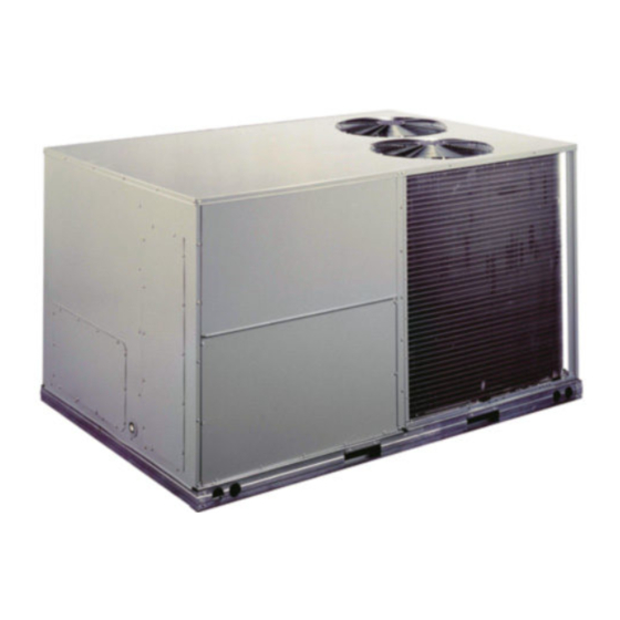
WARNING RATED INDOOR AIRFLOW MODEL NUMBER PERSONAL INJURY AND ENVIRONMENTAL (CFM) HAZARD RHH120 4000 Failure to follow this warning could cause personal injury or death. Relieve pressure and recover all refrigerant before sys- tem repair or final unit disposal. Wear safety glasses and gloves when handling refriger- ants. - Page 3 B = Single Speed Indoor Fan Motor, for W7220 controls Indoor Fan Motor Speed * See RHH 3 to 10 ton Product Specification for details. Fig. 1 — RHH120 Model Number Nomenclature (Example) 516 01 3604 04 Specifications subject to change without notice.
- Page 4 Fig. 2 — Unit Dimensional Drawing — Size 120 Units...
- Page 5 Fig. 2 — Unit Dimensional Drawing — Size 120 Units (cont)
-
Page 6: Refrigeration System Components
LOCATION DIMENSION CONDITION 48-in. (1219 mm) Unit disconnect is mounted on panel 18-in. (457 mm) No disconnect, convenience outlet option 18-in. (457 mm) Recommended service clearance 12-in. (305 mm) Minimum clearance 42-in. (1067 mm) Surface behind servicer is grounded (e.g., metal, masonry wall) 36-in. -
Page 7: Refrigerant System Pressure Access Ports
LPS/LOC Filter Drier Cooling Liquid Lines DFT 1 Acutrol Acutrol Reversing Valve DFT 2 Comp 2 Reversing Valve Indoor Coil Comp 1 Outdoor Coil Heating Mode Liquid Lines Strainer Fig. 4 — Typical Unit Piping Schematic SEAT CORE (Part No. EC39EZ067) 1/2-20 UNF RH 0.596 45°... -
Page 8: Step 1 - Plan For Unit Location
Table 5 — Operating Weights function properly. Unit leveling tolerances are shown in Fig. 7. Refer to Accessory Roof Curb Installation Instruc- tions for additional information as required. RHH120 COMPONENT UNIT LB (KG) Install insulation, cant strips, roofing felt, and counter flash- ing as shown. - Page 9 50TM500827 Fig. 6 — Roof Curb Details...
-
Page 10: Step 5 - Field Fabricate Ductwork
UNITS WITH ACCESSORY ELECTRIC HEATERS All installations require a minimum clearance to combustible surfaces of 1-in. (25 mm) from duct for first 12-in. (305 mm) away from unit. Step 6 — Rig and Place Unit Keep unit upright and do not drop. Spreader bars are re- quired. -
Page 11: Positioning On Curb
36” - 54” “C” DETAIL “A” DUCT END “A” SEE DETAIL “A” DIMENSIONS MAX WEIGHT UNIT RHH120 2075 116.0 2945 58.5 1485 59.5 1510 NOTES: 1. SPREADER BARS REQUIRED — Top damage will occur if spreader bars are not used. -
Page 12: Step 8 - Install Outside Air Hood
NOTCHES NOTCHES BASEPAN Fig. 11 — Location of Notches SCREWS FILTER ACCESS PANEL INDOOR COIL ACCESS PANEL Fig. 13 — Typical Access Panel Locations REMOVE HOOD PARTS DUCT COVERS SHEET METAL FACE UP CUT PLASTIC TIES (2) PLACES ECONOMIZER BASEPAN Fig. -
Page 13: Economizer And Two-Position Hood
PANEL HOOD PARTS RAIN DEFLECTORS PLASTIC TIE WRAP PANEL QTY (2) CAULK HERE INDOOR INDOOR COIL COIL ACCESS ACCESS PANEL PANEL SCREWS FOR METAL TRAY Fig. 16 — Indoor Coil Access Panel Relocation QTY (2) Fig. 15 — Damper Assembly PANEL ECONOMIZER AND TWO-POSITION HOOD ASSEMBLY... -
Page 14: Step 9 - Install External Condensate Trap And
Step 9 — Install External Condensate Trap and Step 10 — Make Electrical Connections Line The unit has one -in. condensate drain connection on the WARNING end of the condensate pan and an alternate connection on the bottom. See Fig. 19. Unit airflow configuration does not ELECTRIC SHOCK HAZARD determine which drain connection to use. - Page 15 Fig. 22 — Conduit into Control Box Fig. 25 — Mounting Position for Field Disconnects (up to 100A) All units except 208/230-v units are factory wired for the voltage shown on the nameplate. If the 208/230-v unit is to be connected to a 208-v power supply, the control trans- former must be rewired by moving the black wire with the -in.
-
Page 16: All Units
NOTE: TEST LEADS — Unit may be equipped with short shown in the following example to determine the percent of voltage imbalance. test leads (pigtails) on the field line connection points on contactor C or optional disconnect switch. These leads are for factory-run test purposes only;... -
Page 17: Convenience Outlets
Fig. 28 — Location of Non-Fused Disconnect Fig. 29 — Handle and Shaft Assembly for NFD Enclosure CONVENIENCE OUTLETS To field install the NFD shaft and handle (Fig. 29): 1. Remove the unit front panel (see Fig. 2). WARNING 2. Remove (3) hex screws on the NFD enclosure - (2) on the face of the cover and (1) on the bottom. - Page 18 PWD-CO FUSE SWITCH PWD-CO TRANSFORMER CONVENIENCE OUTLET GFCI UNIT CONNECT PRIMARY TRANSFORMER DISCONNECT VOLTAGE CONNECTIONS TERMINALS ACCESS PANEL L1: RED + YEL H1 + H3 Fig. 30 — Convenience Outlet Location 208, 230 L2: BLU + GRA H2 + H4 L1: RED Unit-Powered Convenience Outlet Splice BLU + YEL...
-
Page 19: Factory-Option Thru-Base Connections
Installing Weatherproof Cover A weatherproof while-in-use cover for the factory-installed convenience outlets is now required by UL standards. This cover cannot be factory-mounted due its depth; it must be installed at unit installation. For shipment, the convenience LOW VOLTAGE outlet is covered with a blank cover plate. CONDUIT CONNECTOR The weatherproof cover kit is shipped in the unit’s control... -
Page 20: Central Terminal Board
Typical Central Thermostat Terminal Connections Board (Note 2) O/B/Y2 (Note 1) SWITCHES NOTES: 1. Typical multi-function marking. Follow manufacturer’s configuration instructions to select Y2. Do not configure for O output. 2. W2 connection not required on units without electric heating. Field Wiring SPEED-UP Fig. - Page 21 Fig. 36 — Defrost Control Board Location Table 6 — RHH Defrost Board I/O and Jumper Configurations POINT NAME TYPE OF I/O CONNECTION PIN NUMBER UNIT CONNECTION NOTE INPUTS G Fan DI, 24 vac P2-3 CTB-G Y1 Cool 1 DI, 24 vac P2-5 CTB-Y1 Y2 Cool 2...
-
Page 22: Unit Without Thru-Base Connection Kit
Defrost The defrost control mode is a time/temperature sequence. There are two time components: The continuous run period and the test/defrost cycle period. The temperature compo- nent is provided by Defrost Thermostat 1 and 2 (DFT1 and DFT2) mounted on the outdoor coil. The continuous run period is a fixed time period between the end of the last defrost cycle (or start of the current Heat- ing cycle) during which no defrost will be permitted. -
Page 23: Control And Power Wiring Diagrams
SINGLE HEATER MANUAL RESET POINT BOX COVERS LIMIT SWITCH DISCONNECT MOUNTING LOCATION SINGLE POINT HEATER HEATER HEATER MODULE MODULE MOUNTING MOUNTING (LOCATION 1) (LOCATION 2) BRACKET SCREW Fig. 39 — Typical Component Location Single Point Boxes Heater and Supplementary Fuses When heaters are installed, power wiring to both heaters When the unit MOCP device value exceeds 60-A, unit- and the rest of the unit is connected via the single point box... - Page 24 NOTE: Optional Outdoor Temperature Control at One Heater Stage – Move either heater wire to this terminal and connect outdoor temperature switch between second and third terminals. Fig. 41 — Accessory Electric Heater Control Connections 516 01 3604 04 Specifications subject to change without notice.
- Page 25 Fig. 42 — Typical RHH Control Wiring Diagram...
- Page 26 Fig. 43 — Typical RHH Power Wiring Diagram (208/230-3-60 unit shown) 516 01 3604 04 Specifications subject to change without notice.
-
Page 27: Economi$Er® X (Factory Option)
Economi$er X (Factory Option) ® User Interface The interface provides status for normal operation, setup The EconoMi$er X system is an expandable economizer parameters, checkout tests, and alarm and error conditions control system, which includes a W7220 economizer mod- with a 2-line 16 character LCD display and four button ule (controller) with an LCD and keypad (see Fig. -
Page 28: Environmental
ENVIRONMENTAL Table 8 — Economizer Module - Left Hand Terminal Operating Temperature Blocks –40°F to 150°F (–40°C to 65°C). LABEL TYPE DESCRIPTION Exception of display operation down to –4°F with full recov- Top Left Terminal Block ery at –4°F from exposure to –40°F 20k NTC Mixed Air Temperature Sensor (Polarity Storage Temperature... -
Page 29: Interface Overview
SENSOR (HOT) BLACK YELLOW ANALOG BROWN – ORANGE GREEN POWER SUPPLY. PROVIDE DISCONNECT MEANS AND OVERLOAD PROTECTION Switch AS REQUIRED. Label Fig. 47 — CO Sensor Wiring INTERFACE OVERVIEW This section describes how to use the EconoMi$er X user ® Switches interface for: •... - Page 30 To use the keypad when working with Setpoints, System and Advanced Settings, Checkout tests and Alarms: IMPORTANT: Table 12 illustrates the complete hierarchy. 1. Navigate to the desired menu. Your menu parameters may be different depending on 2. Press the (Enter) button to display the first item in your configuration.
- Page 31 Table 12 — Menu Structure* PARAMETER PARAMETER MENU PARAMETER DEFAULT RANGE AND NOTES VALUE INCREMENT † FIRST STAGE COOLING DEMAND (Y1–IN) ECONO AVAIL YES/NO YES = economizing available; the system can use outside air for free cooling when required FIRST STAGE COOLING RELAY OUTPUT ECONOMIZING YES/NO YES = outside air being used for 1 stage cooling...
- Page 32 Table 12 — Menu Structure* (cont) PARAMETER PARAMETER MENU PARAMETER DEFAULT RANGE AND NOTES VALUE INCREMENT † OK/Alarm (on ACTUATOR Displays ERROR if voltage or torque is below actuator range. Alarm menu) EXHAUST STAGE 1 RELAY OUTPUT Output of EXH1 terminal: EXH1 OUT ON/OFF ON = relay closed...
- Page 33 Table 12 — Menu Structure* (cont) PARAMETER PARAMETER MENU PARAMETER DEFAULT RANGE AND NOTES VALUE INCREMENT † Display order = MM/DD/YY INSTALL 01/01/10 Setting order = DD, MM, then YY. UNITS DEG F or C Sets economizer controller in degrees Fahrenheit or Celsius CONV = conventional;...
- Page 34 Table 12 — Menu Structure* (cont) PARAMETER PARAMETER MENU PARAMETER DEFAULT RANGE AND NOTES VALUE INCREMENT † OUTSIDE AIR HUMIDITY CALIBRATION OA H CAL 0% RH ±10% RH Allows for operator to adjust for an out of calibration humidity sensor. RETURN AIR TEMPERATURE CALIBRATION RA T CAL 0.0°F...
- Page 35 Table 12 — Menu Structure* (cont) PARAMETER PARAMETER MENU PARAMETER DEFAULT RANGE AND NOTES VALUE INCREMENT † When AUX1-O is set to SYS and there is any alarm (e.g., failed SYS ALARM sensors, etc.), the AUX1-O terminal has 24 Vac out. ACTUATOR VOLTAGE LOW ACT UNDER V Voltage received by actuator is above expected range.
- Page 36 Table 15 — Dry Bulb Operation, with Demand Controlled Ventilation (DCV) (CO Sensor) — 1 Speed Fan OUTSIDE AIR GOOD TO Y1-I Y2-I FAN SPEED Y1-O Y2-O OCCUPIED UNOCCUPIED ECONOMIZE? High 0-v/Off 0-v/Off VENTMIN Closed High 24-v/On 0-v/Off VENTMIN Closed High 24-v/On 24-v/On...
- Page 37 Table 18 — Dry Bulb Operation, No Demand Controlled Ventilation (DCV) (CO Sensor) — 2 Speed Fan OUTSIDE AIR GOOD TO Y1-I Y2-I FAN SPEED Y1-O Y2-O OCCUPIED UNOCCUPIED ECONOMIZE? 0-v/Off 0-v/Off MIN POS L Closed 24-v/On 0-v/Off MIN POS L Closed High 24-v/On...
-
Page 38: Enthalpy Settings
Table 21 — Enthalpy Operation, with Demand Controlled Ventilation (DCV) (CO Sensor) — 2 Speed Fan OUTSIDE AIR GOOD TO Y1-I Y2-I FAN SPEED Y1-O Y2-O OCCUPIED UNOCCUPIED ECONOMIZE? 0-v/Off 0-v/Off VENTMIN L Closed 24-v/On 0-v/Off VENTMIN L Closed High 24-v/On 24-v/On VENTMIN H... -
Page 39: Two-Speed Fan Operation
TWO-SPEED FAN OPERATION Power Loss (Outage or Brownout) All setpoints and advanced settings are restored after any The W7220 controller has the capability to work with a sys- power loss or interruption. tem using a 2-speed supply fan. The W7220 does not con- trol the supply directly but uses the following input status to NOTE: All settings are stored in non-volatile flash memory. -
Page 40: Smoke Detectors
Smoke Detectors RETURN AIR Smoke detectors are available as factory-installed options SMOKE DETECTOR on RHH models. Smoke detectors may be specified for sup- (AS SHIPPED) ply air only, return air without or with economizer, or in com- bination of supply air and return air. Return-air smoke detectors are arranged for vertical return configurations on- ly. -
Page 41: Step 12 - Install Accessories
Fig. 52 — EconoMi$er IV Wiring Step 12 — Install Accessories BELT FORCE — DEFLECTION METHOD Available accessories include: Check the belt tension with a spring-force belt force deflec- tion gage (available from drive belt manufacturer). • Roof curb 1. Place a straightedge along the belt between the two •... -
Page 42: Pre-Start And Start-Up
BELT DEFLECTION FORCE - SEE TABLE 1 BLOWER PULLEY V-BELT DEFLECTION = BELT SPAN MOTOR STRAIGHT PULLEY EDGE SCREW SCREW MOTOR TORQUE ALL SHEAVE SET SCREWS TO 110-130 in. lbs TABLE 1 BELT DEFLECTION FORCE (LBS) BELT SMALLEST UNNOTCHED MOUNTING CROSS SHEAVE NOTCHED BELTS... -
Page 43: Start-Up Checklist
START-UP CHECKLIST RHH120 Single Package Rooftop Heat Pump (Remove and use for job file) NOTE: To avoid injury to personnel and damage to equipment or property when completing the procedures listed in this start-up checklist, use good judgment, follow safe practices, and adhere to the safety considerations/information as outlined in preceding sections of this Installation Instruction document. - Page 44 HEATING CYCLE ELECTRICAL Supply Voltage L1-L2_____________ L2-L3_____________ L3-L1_____________ Compressor Amps 1 L1 _____________ L2 _____________ L3 _____________ Compressor Amps 2 L1 _____________ L2 _____________ L3 _____________ Supply Fan Amps L1 _____________ L2 _____________ L3 _____________ TEMPERATURES Outdoor-air Temperature _____________ °F DB (Dry Bulb) Return-air Temperature _____________ °F DB _____________ °F Wb (Wet Bulb)
Need help?
Do you have a question about the RHH120 and is the answer not in the manual?
Questions and answers