Table of Contents
Advertisement
Installation Instructions
PHF3 Series
2 to 4 TON
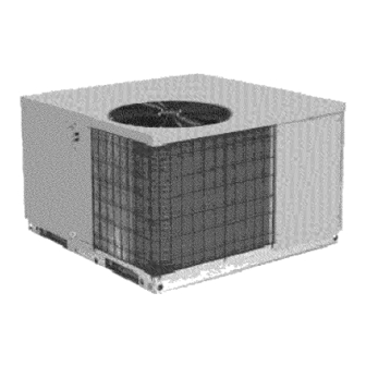
PACKAGE HEAT PUMPS
TABLEOF CONTENTS
UNITDIMENSIONS.........................................
2
SAFEINSTALLATION REQUIREMENTS .........................
3
LOCATING THE UNIT .......................................
3
CLEARANCES ............................................
3
INSTALLATION............................................
3
GROUNDLEVELINSTALLATION ..............................
4
ROOFTOPINSTALLATION...................................
4
HOISTING................................................
4
DOWNFLOWCONVERSION ..................................
4
CONDENSATE DRAIN .......................................
4
ELECTRICALWIRING ...................................
5
DUCTWORK..........................................
6
FILTERS .............................................
6
AIRFLOWADJUSTMENT ................................
7
START-UPPROCEDURES ...............................
7
SEQUENCEOF OPERATION..............................
8
MAINTENANCE .......................................
9
RIGGING ...........................................
11
WIRING DIAGRAMS ................................
12- 13
C_US
°_'_° _°_ °
LISTED
518 01 1201 01
2-18-09
Printed in U.S.A.
Advertisement
Table of Contents

Summary of Contents for ICP PHF348000K00A1
-
Page 1: Table Of Contents
Installation Instructions PHF3 Series 2 to 4 TON PACKAGE HEAT PUMPS TABLEOF CONTENTS UNITDIMENSIONS......... ELECTRICALWIRING ........SAFEINSTALLATION REQUIREMENTS ......DUCTWORK.......... LOCATING THE UNIT ........FILTERS ..........CLEARANCES ..........AIRFLOWADJUSTMENT ........ INSTALLATION..........START-UPPROCEDURES ....... GROUNDLEVELINSTALLATION ......SEQUENCEOF OPERATION......ROOFTOPINSTALLATION........MAINTENANCE ........HOISTING.......... -
Page 2: Unitdimensions
"A" ..E3:-I 3/4. 46-1/2" Detail BASE PAN - CHASSIS 42-3/4"* " BASE RAIL 46-1 8** --" 12-1/4 Condensate Drain RETURN 1-3/4 1-9/16 2-3/16 2-3/16 3-3/4 UNIT SIZE 2Ton 29-1/2 47-1/2 47-1/2 9-1/2 4-1/2 2-1/2 to 4 Ton 37-1/2 47-1/2 47-1/2 6-1/2 4-1/2... -
Page 3: Safeinstallation Requirements
2. SAFE INSTALLATION REQUIREMENTS Minimum Clearances to Combustible Construction Duct Side ....2" (6" on large chassis models) Condenser Inlet ........30" Blower Service (Side) ....... 30" FIRE AND ELECTRICAL SHOCK HAZARD Control Service Side (Front Combustion Air Inlet) ....30"... -
Page 4: Rooftopinstallation
Condensate Drain Rooftop Installation Rooftop platform requirements: The condensate drain outlet is (19.1 mm) female PVC a 3/4" connection located at the bottom on the left hand side (see - The unit MUST be situated to provide safe access for FIGURE 2). - Page 5 For 2 to 3-1/2 Ton Models Only: A single stage thermostat is required for proper operation. REDUCED EQUIPMENT LIFE HAZARD Thermostat must have the terminals shown in Figure 3 or there equivalent. Some electronic thermostats use low Failure to follow these precautions could result voltage from the unit for power for temperature display and...
-
Page 6: Ductwork
1 x 20" x 24" 1 x 15" x 20" PHF336000K00A1 2 x 15" x 20" 1 x 18" x 20" PHF342000K00A1 2 x 18" x 20" 1 x 20" x 20" PHF348000K00A1 2 x 20" x 20" 1 x 20" x 24"... -
Page 7: Airflowadjustment
6. AIRFLOW ADJUSTMENT CIRCULATING AIR BLOWER SPEEDS BLOWERPERFORMANCEDATA _odel Number PHF324000K00AI PHF330000K00AI PHF336000K00A1 PHF342000K00A1 PHF348000K00A1 3peedTap 1136 1076 1286 1352 1162 1278 1529 1652 1138 1240 1505 1643 1154 1245 1750 1908 1098 1038 1225 1311 1118 1233 1484 1607... -
Page 8: Sequenceof Operation
8. SEQUENCE OF OPERATION case of staged heating. When heating demand is satisfied, W3, W2 and Y2 sequentially de-energize switching the compressor and the indoor fan into low stage heating. When low stage heating demand is met, ELECTRICAL SHOCK HAZARD. de-energizes shutting the compressor, indoor fan and the outdoor fan. -
Page 9: Maintenance
reversing valveandauxiliary heatoutputs and"hold" COOLING SEASON CHECKS (MONTHLY) thedefrost timeruntil t henextcall f orheat, a twhich time Condenser Coil thedefrost c yclewillbecompleted. Keep the condenser inlet and outlet area clean and free of Servicetesting: the pins marked"speed up" when leaves, grass clippings or other debris. Grass should be momentarily shorted together ( for5seconds) andreleased, kept short in front of the condenser inlet. - Page 10 Control Box Control Plate Capacitor Strap Run Capacitor Defrost Board Motor Board Transformer Contactor 11ol...
-
Page 11: Rigging
10. Rigging Instructions Rigging Instructions < <_ <_ _J_z El- a EtZ EtZ EL o >w © S8 £s _--) 09-- O2>- <_o (Din W_< © .__. r- L!!_1... -
Page 12: Wiring Diagrams
10. Wiring Diagrams FIELD SUPPLY POWER ± SIZE 2 AWG. EQUIP GNt .."COMPRESSOR P UG FOR WIRINGWI'IH I--/--_ E_:c'mm I.e.Kms ._-'.1 L ONHEA'IBR ACCeSSO_[L ....__ DE_ROS] BOARD (DB) NOTE !.-- PL 1 ACCESSSORY ELECTRIC ,T,,I HR1,2,3 & 4 (20 HR1 &... -
Page 13: Speed Tap
FIELD SCHEMATIC BLN _ B'rN-- SUPPLY DR @ DB 208/230-1-60 POWER BL__ MAXIMUM WIRE-- UNIT ONIY [ L¶-- SIZE 2 AWG, PLUG E©UZP COMP SOL FOR WIRK; W]'111 [/--_ B.ECmm H_S I "._ sE SCH_t_C ..k_ I_ ON HEA'I_ ACCESSORY, --BLK SEE NOTE #5_ TRANI...


Need help?
Do you have a question about the PHF348000K00A1 and is the answer not in the manual?
Questions and answers