Table of Contents
Advertisement
Installation Instructions
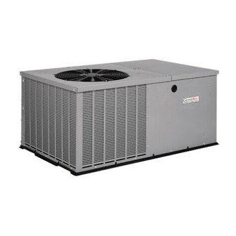
PHX3 Series
2 to 5 TON
PACKAGE HEAT PUMPS
TABLEOF CONTENTS
UNITDIMENSIONS ......................................
2 - 3
SAFEINSTALLATIONREQUIREMENTS .........................
4
LOCATING THE UNIT .......................................
4
CLEARANCES ............................................
4
INSTALLATION............................................
5
GROUNDLEVELINSTALLATION ..............................
5
RooftopINSTALLATION.....................................
5
HOISTING................................................
5
DOWNFLOWCONVERSION ..................................
5
CONDENSATEDRAIN.......................................
5
ELECTRICALWIRING ...................................
6
DUCTWORK..........................................
7
FILTERS .............................................
7
AIRFLOWADJUSTMENT ................................
8
START-UPPROCEDURES ...............................
9
SEQUENCEOF OPERATION..............................
9
MAINTENANCE ......................................
10
RIGGING ...........................................
12
WIRING DIAGRAMS ...................................
13
_
CLIS_IEDUS
518 O1 1301 OO
1-4-O6
Printed in U.S.A.
CODE: PHX3
Advertisement
Table of Contents

Summary of Contents for ICP PHX330000K00A1
-
Page 1: Table Of Contents
Installation Instructions PHX3 Series 2 to 5 TON PACKAGE HEAT PUMPS TABLEOF CONTENTS UNITDIMENSIONS ........2 - 3 ELECTRICALWIRING ........SAFEINSTALLATIONREQUIREMENTS ......DUCTWORK.......... LOCATING THE UNIT ........FILTERS ..........CLEARANCES ..........AIRFLOWADJUSTMENT ........ INSTALLATION..........START-UPPROCEDURES ....... GROUNDLEVELINSTALLATION ......SEQUENCEOF OPERATION......RooftopINSTALLATION........ -
Page 2: Unitdimensions
"B" CHASSIS UNIT DIMENSIONS 1. Unit Dimensions Units in "B" Chassis Configuration PACKAGE HEAT PUMP UNITS PHX324 - 36 "B" Chassis (473/8 x 473/8) DIM. INCHES MILLOMETERS 47-3/8 1203 47-3/8 1203 3-1/8 32-1/2 11-1/8 14-1/4 .¢-..14-1/4 "4 "A" 314_I 19_28 _I _J'"_ "1''/ 4-1/4... - Page 3 "C" CHASSIS UNIT DIMENSIONS POWER CONDUIT ('K" DIM.) VOLTAGE (12.7) CONDUIT PACKAGE HEAT PUMP UNITS "C" Chassis (473/8 x 73) INCHES MILLOMETER8 47-3/8 1203 1354 4-5/8 18-3/4 18-3/4 1 &1-1/4 25&31 4-1/4 5-1/4 12-1/4 12-1/4 ,,p,, 16-7/8 UNIT BASE SHOWN SEPARATELY BLLUSTRATE BOTTOM...
-
Page 4: Safeinstallationrequirements
2. SAFE INSTALLATION REQUIREMENTS FIRE, AND ELECTRICAL SHOCK HAZARD Installation and servicing of air-conditioning equipment can be hazardous due to system pressure and electrical Failure to carefully read and follow all instructions in this components. Only trained and qualified personnel should manual could result in furnace... -
Page 5: Installation
Do NOT install the unit in a location that will permit - Platform must be high enough to allow for proper discharged air from the condenser to recirculate to the condensate trap installation and drainage. See Figure 2 and associated text for more information about condenser inlet,... -
Page 6: Electricalwiring
The circulating blower creates a negative pressure on the condensate drain line that can prevent the condensate from draining properly. To combat this negative pressure, a field REDUCED EQUIPMENT LIFE HAZARD supplied condensate trap that will allow a standing column Failure to follow these precautions... -
Page 7: Ductwork
Minimum Area (sq xwxd) inches) xwxd) inches) PHX324000K00A1 1 x 20" x 20" 1 x 10" x 20" PHX330000K00A1 1 x 20" x 24" 1 x 12" x 20" PHX336000K00A1 2x 15"x20" 1 x 15" x20" PHX342000K00A1 2x 18"x20" 1 x 18" x20"... -
Page 8: Airflowadjustment
6. AIRFLOW ADJUSTMENT CIRCULATING AIR BLOWER SPEEDS ModelNumber PHX324 PHX330 PHX336 Torque(ox Ft.} 1098 1553 18.04 29.02 11.92 1302 18.04 23.06 29.02 1859 24.00 34.35 52.94 Speed Tap I201 1100 I250 1026 12/0 1030 I218 1080 I227 1242 I588 I194 1048 I201 1209... -
Page 9: Start-Upprocedures
7. START-UP PROCEDURES stage (W2). If the demand is not met, W3 is energized incase of staged heating. When heating demand satisfied, W3, W2 and Y2 sequentially de-energize CHECK BEFORE STARTING switching the compressor and the indoor fan into low stage 1. -
Page 10: Maintenance
4. Should the system indoor thermostat be satisfied COOLING SEASON CHECKS (MONTHLY) during the defrost cycle, the control will de-energize the Condenser Coil reversing valve and auxiliary heat outputs and "hold" Keep the condenser inlet and outlet area clean and free of the defrost timer until the next call for heat, at which time leaves, grass clippings or other debris. - Page 11 FIGURE 7 Control Defrost Motor Board Board Transformer Contactor Run Capacitor Capacitor Strap...
-
Page 12: Rigging
R GG NG INSTRUCTIONS fAiLURE TOfOLLOW - _-SE _.STRUC-r_O_S WA_\ RESULT IN PROPERTY DAMAGE, BoD,_,_u_R_ oRDEAT_ - ALL PANELS MUST IN PLACE WHEN RIGGING LIFTING. - HOOK RIGGING SHACKLES THROUGH HOLES IN BASE RAIL, SHOWN IN DETAIL-A. - USE SPREADER BARS, WHEN RIGGING,... -
Page 13: Wiring Diagrams
11. Wiring Diagrams 2 to 5 Ton Wiring Diagram SO! [_£1 :IC...


Need help?
Do you have a question about the PHX330000K00A1 and is the answer not in the manual?
Questions and answers