
Related Manuals for Oshkosh Corporation JLG R2632


Summary of Contents for Oshkosh Corporation JLG R2632
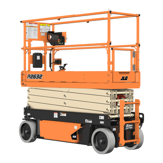
- Page 1 Operation and Safety Manual Original Instructions - Keep this manual with the machine at all times. Models R2632 R3246 PVC 2010 ANSI AS/NZS 31215932 September 1, 2020 - Rev A ®...
- Page 2 WARNING Operating, servicing and maintaining this vehicle or equipment can expose you to chemicals including engine exhaust, carbon monoxide, phthalates, and lead, which are known to the State of California to cause cancer and birth defects or other reproductive harm. To minimize exposure, avoid breathing exhaust, do not idle the engine except as necessary, service your vehicle or equipment in a well-ventilated area and wear gloves or wash your hands frequently when servicing.
- Page 3 FOREWORD FOREWORD The Mobile Elevating Work Platform (MEWP) models covered in this manual are designed and tested to meet or exceed various compliance standards. Please refer to the manufacturer’s nameplate affixed to the subject MEWP for specific standard compliance information. This manual is a very important tool! Keep it with the machine at all times.
- Page 4 SAFETY ALERT SYMBOLS AND SAFETY SIGNAL WORDS SAFETY ALERT SYMBOLS AND SAFETY SIGNAL WORDS THIS IS THE SAFETY ALERT SYMBOL. IT IS USED TO ALERT YOU TO THE POTENTIAL PERSONAL INJURY HAZ- ARDS. OBEY ALL SAFETY MESSAGES THAT FOLLOW THIS SYMBOL TO AVOID POSSIBLE INJURY OR DEATH. INDICATES AN IMMINENTLY HAZARDOUS SITUATION.
- Page 5 SAFETY ALERT SYMBOLS AND SAFETY SIGNAL WORDS For: • Accident Reporting • Standards and Regulations THIS PRODUCT MUST COMPLY WITH ALL SAFETY RELATED BULLETINS. CON- Compliance Information TACT JLG INDUSTRIES, INC. OR THE LOCAL AUTHORIZED JLG REPRESENTA- • Product Safety Publica- TIVE FOR INFORMATION REGARDING SAFETY RELATED BULLETINS WHICH tions •...
- Page 6 REVISION LOG REVISION LOG Original Issue - A ......September 1, 2020 31215932...
-
Page 7: Table Of Contents
TABLE OF CONTENTS SECTION - 1 - SAFETY PRECAUTIONS PRE-START INSPECTION ........2-4 WALK-AROUND INSPECTION . - Page 8 TABLE OF CONTENTS Lift/Drive Selector Switch ......3-10 3.13 PARKING AND STOWING MACHINE..... .3-22 Forward/Reverse/Lift/Lower Directional Arrow .
- Page 9 TABLE OF CONTENTS Preparation and Inspection......5-5 SUPPLEMENTAL INFORMATION ......6-2 Operation .
- Page 10 TABLE OF CONTENTS Diagram..........6-14 Decals .
-
Page 11: Section 1. Safety Precautions
SECTION 1 - SAFETY PRECAUTIONS SECTION 1. SAFETY PRECAUTIONS GENERAL PRE-OPERATION Operator Training and Knowledge This section outlines the necessary precautions for proper and safe machine usage and maintenance. In order to promote • Read, understand, and study the Operation and Safety Manual in proper machine usage, it is mandatory that a daily routine is its entirety before operating the machine. ... -
Page 12: Workplace Inspection
SECTION 1 - SAFETY PRECAUTIONS Machine Inspection • All operating personnel must have a thorough understanding of the intended purpose and function of the MEWP controls, includ- • Do not operate this machine until the inspections and functional ing platform, ground and emergency descent controls. checks have been performed as specified in Section 2 of this man- •... -
Page 13: Operation
SECTION 1 - SAFETY PRECAUTIONS OPERATION • Do not carry materials directly on platform railing unless approved by JLG. General • When two or more persons are in the platform, the operator shall be responsible for all machine operations. • Machine operation requires your full attention. Bring the machine •... -
Page 14: Trip And Fall Hazards
SECTION 1 - SAFETY PRECAUTIONS Trip and Fall Hazards • Prior to operation, ensure all gates and rails are fastened and secured in their proper position. • JLG Industries, Inc. recommends that all persons in the platform wear a full body harness with a lanyard attached to an authorized lanyard anchorage point while operating this machine. -
Page 15: Electrocution Hazards
SECTION 1 - SAFETY PRECAUTIONS Electrocution Hazards • This machine is not insulated and does not provide protection from contact or proximity to electrical current. • The minimum approach distance may be reduced if insulating • It is not recommended to use the machine during lightning. To barriers are installed to prevent contact, and the barriers are rated prevent injury or machine damage if lightning occurs during oper- for the voltage of the line being guarded. -
Page 16: Tipping Hazards
SECTION 1 - SAFETY PRECAUTIONS Table 1-1. Minimum Approach Distances (M.A.D.) • Before driving on floors, bridges, trucks, and other surfaces, check allowable capacity of the surfaces. VOLTAGE RANGE MINIMUM APPROACH DISTANCE • Never exceed the maximum platform capacity as specified on the (Phase to Phase) in Feet (Meters) platform. - Page 17 SECTION 1 - SAFETY PRECAUTIONS DO NOT OPERATE THE MACHINE WHEN WIND CONDITIONS EXCEED SPECIFICATIONS SHOWN IN SECTION 6.3 OR AS SHOWN ON THE CAPACITY PLACARD ON THE PLAT- FORM BILLBOARD. Table 1-2. Beaufort Scale (For Reference Only) WIND SPEED BEAUFORT DESCRIPTION LAND CONDITIONS...
- Page 18 SECTION 1 - SAFETY PRECAUTIONS • Never attempt to use the machine as a crane. Do not tie-off machine to any adjacent structure. Never attach wire, cable, or any similar items to platform. • If the scissor arm assembly or platform is caught so that one or more wheels are off the ground, all persons must be removed before attempting to free the machine.
-
Page 19: Crushing And Collision Hazards
SECTION 1 - SAFETY PRECAUTIONS Crushing and Collision Hazards • Always post a lookout when driving in areas where vision is obstructed. • Approved head gear must be worn by all operating and ground • Keep non-operating personnel at least 6 ft (1.8 m) away from personnel. -
Page 20: Towing, Lifting, And Hauling
SECTION 1 - SAFETY PRECAUTIONS TOWING, LIFTING, AND HAULING MAINTENANCE • Never allow personnel in platform while towing, lifting, or hauling. This sub-section contains general safety precautions which must be observed during maintenance of this machine. Additional pre- • This machine should not be towed, except in the event of emer- cautions to be observed during machine maintenance are gency, malfunction, power failure, or loading/unloading. -
Page 21: Battery Hazards
SECTION 1 - SAFETY PRECAUTIONS Battery Hazards • Always relieve hydraulic pressure from all hydraulic circuits before loosening or • Always disconnect batteries when servicing electrical compo- removing hydraulic components. nents or when performing welding on the machine. • DO NOT use your hand to check for •... - Page 22 SECTION 1 - SAFETY PRECAUTIONS NOTES: 1-12 31215932...
-
Page 23: Section 2 - User Responsibilities, Machine Preparation, And Inspection
SECTION 2 - USER RESPONSIBILITIES, MACHINE PREPARATION, AND INSPECTION SECTION 2. USER RESPONSIBILITIES, MACHINE PREPARATION, AND INSPECTION PERSONNEL TRAINING Selection of the appropriate MEWPs and available options for the work to be performed considering specific job requirements, with involvement from the MEWP owner, user, The Mobile Elevating Work Platform (MEWP) is a personnel handling and/or supervisor. -
Page 24: Machine Familiarization
SECTION 2 - USER RESPONSIBILITIES, MACHINE PREPARATION, AND INSPECTION PREPARATION, INSPECTION, AND MAINTENANCE Machine Familiarization NOTE: Responsibilities for familiarization may vary by region. The following table covers machine inspections and maintenance required by JLG Industries, Inc. Consult local regulations for further Only properly trained personnel who have received unit-specific requirements for MEWPs. -
Page 25: Inspection And Maintenance Table
SECTION 2 - USER RESPONSIBILITIES, MACHINE PREPARATION, AND INSPECTION Inspection and Maintenance Table PRIMARY SERVICE TYPE FREQUENCY REFERENCE RESPONSIBILITY QUALIFICATION Pre-Start Inspection Before using each day, or whenever there’s an operator change. User or Operator User or Operator Operation and Safety Manual Pre-Delivery Inspection Service and Maintenance Manual and appli- Before each sale, lease, or rental delivery. -
Page 26: Pre-Start Inspection
SECTION 2 - USER RESPONSIBILITIES, MACHINE PREPARATION, AND INSPECTION PRE-START INSPECTION Walk-Around Inspection – Perform as instructed in Section 2.4. The Pre-Start Inspection should include each of the following: Battery – Charge as required. Cleanliness – Check all surfaces for leakage (oil or battery Hydraulic Oil Level –... - Page 27 SECTION 2 - USER RESPONSIBILITIES, MACHINE PREPARATION, AND INSPECTION Lanyard Attach Points 31215932...
-
Page 28: Walk-Around Inspection
SECTION 2 - USER RESPONSIBILITIES, MACHINE PREPARATION, AND INSPECTION WALK-AROUND INSPECTION Ground Control Console – Placard secure and legible, con- trol switches return to neutral position when activated and released, emergency stop switch functions properly. Control Begin the Walk-Around Inspection at item 1 as noted on the Inspec- markings legible. -
Page 29: Inspection Diagram
SECTION 2 - USER RESPONSIBILITIES, MACHINE PREPARATION, AND INSPECTION Inspection Diagram OAD00621 31215932... -
Page 30: Function Check
SECTION 2 - USER RESPONSIBILITIES, MACHINE PREPARATION, AND INSPECTION FUNCTION CHECK From the Platform Control Console: a. Ensure the control console is firmly secured in the Perform the Function Check as follows: proper location. b. Ensure all guards protecting switches are in place. At the Ground Control Panel with no load in the platform: c. - Page 31 SECTION 2 - USER RESPONSIBILITIES, MACHINE PREPARATION, AND INSPECTION g. With the platform elevated on a smooth, firm, level sur- face with no overhead obstructions, drive the machine Table 2-2. Tilt Activation Setting to check if the high drive cutback speed limit is engaged at the height indicated in Table 2-1.
- Page 32 SECTION 2 - USER RESPONSIBILITIES, MACHINE PREPARATION, AND INSPECTION NOTES: 2-10 31215932...
-
Page 33: Section 3 - Machine Controls, Indicators, And Operation
SECTION 3 - MACHINE CONTROLS, INDICATORS, AND OPERATION SECTION 3. MACHINE CONTROLS, INDICATORS, AND OPERATION GENERAL DESCRIPTION This machine is a Mobile Elevating Work Platform (MEWP) used to NOTICE position personnel, along with their necessary tools and materials at work locations. THE MANUFACTURER HAS NO DIRECT CONTROL OVER MACHINE APPLICATION AND OPER- ATION. -
Page 34: Operating Characteristics And Limitations
SECTION 3 - MACHINE CONTROLS, INDICATORS, AND OPERATION OPERATING CHARACTERISTICS AND LIMITATIONS PLATFORM LOADING Placards The platform maximum rated load capacity is shown on a placard located on the platform billboard and is based upon the machine positioned on a smooth, firm surface, within the limits of the maxi- Important points to remember during operation are provided at the mum operating slope. -
Page 35: Battery Charging
SECTION 3 - MACHINE CONTROLS, INDICATORS, AND OPERATION BATTERY CHARGING After connecting the charger to an AC outlet at the start of the charging cycle, verify normal operation of the LED indi- cators on the charger (refer to Section 6.6). The battery charger AC input plug is located inside the frame at the left rear of the machine next to the battery charger. -
Page 36: Machine Control Locations
SECTION 3 - MACHINE CONTROLS, INDICATORS, AND OPERATION MACHINE CONTROL LOCATIONS Platform Control Station Ground Control Station Side Compartment Door Latch (Both Sides) A/C Plug (Battery Charger Input) Platform Manual Descent A/C Plug (Platform A/C Receptacle Outlet Box) 31215932... -
Page 37: Ground Control Console
SECTION 3 - MACHINE CONTROLS, INDICATORS, AND OPERATION GROUND CONTROL CONSOLE 1. Ground/Platform/OFF Key Selector Switch 5. Hourmeter 2. Platform Lift/Lower Switch 6. Overload Indicator (LSS) 3. Inverter ON/OFF Switch (If Equipped) 7. MDI Indicator (If Equipped) 4. Ground Emergency Stop Button 31215932... -
Page 38: Ground/Platform/Off Key Selector Switch
SECTION 3 - MACHINE CONTROLS, INDICATORS, AND OPERATION Platform Lift/Lower Switch A three-position momentary contact switch DO NOT OPERATE MACHINE FROM THE GROUND CONTROL CONSOLE WITH PERSON- controls raising and lowering of the platform NEL IN THE PLATFORM EXCEPT IN AN EMERGENCY. from the ground control console. -
Page 39: Ground Emergency Stop Switch
SECTION 3 - MACHINE CONTROLS, INDICATORS, AND OPERATION Ground Emergency Stop Switch Overload Indicator (LSS) A red two-position emergency stop switch when The Overload Indicator indicates when the platform positioned to ON with the key selector switch posi- has been overloaded. An audible alarm will also sig- tioned to ground furnishes operating power to the nal when the platform is overloaded. -
Page 40: Mdi Indicator (If Equipped)
SECTION 3 - MACHINE CONTROLS, INDICATORS, AND OPERATION MDI Indicator (If Equipped) The Multifunction Digital Indicator (MDI) displays a Battery Discharge Indicator (BDI), a LCD display showing the current hourmeter read- ing, a system distress LED, and Diagnostic Trouble Codes (DTC) when a functional problem occurs with the machine. -
Page 41: Platform Control Station
SECTION 3 - MACHINE CONTROLS, INDICATORS, AND OPERATION PLATFORM CONTROL STATION 1. Emergency Stop Switch 2. Lift/Drive Selector Switch 3. Forward/Reverse/Lift/Lower Directional Arrow 4. Steer Control Switch and Decal 5. Joystick Controller 6. Trigger Enable Switch 7. Overload Indicator (LSS) 8. -
Page 42: Emergency Stop Switch
SECTION 3 - MACHINE CONTROLS, INDICATORS, AND OPERATION Emergency Stop Switch Lift/Drive Selector Switch NOTE: NOTE: Both ground and platform emergency stop switches must be set When selecting between the Lift and Drive functions the joystick to ON in order to operate the machine. control must be returned to the neutral position for approxi- mately 1/2 second before the function change is operable. -
Page 43: Drive/Lift/Steer Joystick Control
SECTION 3 - MACHINE CONTROLS, INDICATORS, AND OPERATION Drive/Lift/Steer Joystick Control Steering and Traveling Trigger (Enable) Switch - This trigger switch is located on the front of the joystick controller. It acts as an enable and must be depressed before operating the drive, steer, and lift functions. When released, DO NOT DRIVE WITH THE PLATFORM ELEVATED EXCEPT ON A SMOOTH, FIRM SURFACE the function in operation will stop. -
Page 44: Steering
SECTION 3 - MACHINE CONTROLS, INDICATORS, AND OPERATION Steering Raising And Lowering Platform On the platform control station, position the lift/ If the machine was shut drive selector switch to the drive/steer position. down, place the key selec- tor switch to the platform To steer the machine, engage trigger switch and position. -
Page 45: Overload Indicator (Lss)
SECTION 3 - MACHINE CONTROLS, INDICATORS, AND OPERATION Overload Indicator (LSS) Variable Tilt - Platform Restricted Height Indicator The Overload Indicator indicates when the platform has been overloaded. An audible This indicator shows the maximum allowable alarm will also signal when the platform is platform elevation when the machine is within overloaded. -
Page 46: Battery Charge Indicator
SECTION 3 - MACHINE CONTROLS, INDICATORS, AND OPERATION Battery Charge Indicator Indoor/Outdoor Operation Indicator The battery charge indicator displays the cur- The Indoor (green) indicator and the Outdoor rent charge status of the onboard batteries. (yellow) indicator displays the mode in which the machine is currently set to operate. -
Page 47: Grade And Sideslope
SECTION 3 - MACHINE CONTROLS, INDICATORS, AND OPERATION GRADE AND SIDESLOPE 31215932 3-15... -
Page 48: 3.10 Platform Extension
SECTION 3 - MACHINE CONTROLS, INDICATORS, AND OPERATION 3.10 PLATFORM EXTENSION FOR MAXIMUM CAPACITY OF THE DECK EXTENSION, REFER TO MACHINE DIMENSIONS IN SECTION 6.2, OR REFER TO THE CAPACITY PLACARD ON THE PLATFORM BILL- BOARD. DO NOT LOWER THE PLATFORM WITHOUT COMPLETELY RETRACTING THE PLATFORM EXTENSION. -
Page 49: Platform Rails Fold-Down Procedure
SECTION 3 - MACHINE CONTROLS, INDICATORS, AND OPERATION 3.11 PLATFORM RAILS FOLD-DOWN PROCEDURE (IF EQUIPPED) Platform with Rail-in-Rail Extension Deck 31215932 3-17... - Page 50 SECTION 3 - MACHINE CONTROLS, INDICATORS, AND OPERATION To return the rails to the upright position, unfold the rails in the reverse sequence in which they were folded. Firmly pull the rails into position and secure the pins onto the rails. ONLY FOLD DOWN THE RAILS WHEN THE MACHINE IS IN THE STOWED (PLATFORM FULLY LOWERED) POSITION.
-
Page 51: Platform With Dual Rails Extension Deck
SECTION 3 - MACHINE CONTROLS, INDICATORS, AND OPERATION Platform with Dual Rails Extension Deck 31215932 3-19... - Page 52 SECTION 3 - MACHINE CONTROLS, INDICATORS, AND OPERATION NOTE: When setting platform side rails back to upright position be cer- tain the extension platform rail guide is interlocked with the main platform rail once both rails are completely upright. ONLY FOLD DOWN THE RAILS WHEN THE MACHINE IS IN THE STOWED (PLATFORM FULLY LOWERED) POSITION.
-
Page 53: 3.12 Platform Manual Descent
SECTION 3 - MACHINE CONTROLS, INDICATORS, AND OPERATION 3.12 PLATFORM MANUAL DESCENT Use the Platform Manual Descent in the event of total power failure to lower the platform using gravity. The red T-handle is located on the left rear of the machine beside the ladder. Look for the instruction decal located beside the T-handle. -
Page 54: 3.13 Parking And Stowing Machine
SECTION 3 - MACHINE CONTROLS, INDICATORS, AND OPERATION 3.13 PARKING AND STOWING MACHINE Drive the machine to a well-protected and well-ventilated area. Ensure the platform is fully lowered. NOTICE WHEN THE MACHINE IS SHUT DOWN FOR OVERNIGHT PARKING OR BATTERY CHARGING, THE EMERGENCY STOP AND POWER SELECT SWITCHES MUST BE POSITIONED TO OFF TO PREVENT DRAINING THE BATTERIES. -
Page 55: 3.14 Machine Lifting And Tie Down
SECTION 3 - MACHINE CONTROLS, INDICATORS, AND OPERATION 3.14 MACHINE LIFTING AND TIE DOWN The machine may be lifted using a forklift truck. Lift only using the built-in forklift pockets at the rear of the machine and only with the platform in the stowed position. - Page 56 SECTION 3 - MACHINE CONTROLS, INDICATORS, AND OPERATION When transporting the machine, fully lower the platform (stowed are two tie-down/lift lugs at the rear of the machine, and two tie- position) and secure the machine to the truck or trailer deck. There downs and one lifting lug at the front of the machine.
-
Page 57: Towing
SECTION 3 - MACHINE CONTROLS, INDICATORS, AND OPERATION 3.15 TOWING Chock wheels or secure machine with tow vehicle. Press in the Emergency Stop switch at the ground control It is not recommended to tow this machine except in the event of an console to turn off power. -
Page 58: Push Button Brake Release (Aus Market Only)
SECTION 3 - MACHINE CONTROLS, INDICATORS, AND OPERATION Push Button Brake Release (AUS Market Only) NOTE: Some components removed for illustrative purposes. Chock wheels or secure machine with tow vehicle. Pull out emergency stop switch and position the keyswitch to ground mode. Press and hold the yellow button at the rear of the machine for one second to release the brakes. -
Page 59: Section 4 - Emergency Procedures
SECTION 4 - EMERGENCY PROCEDURES SECTION 4. EMERGENCY PROCEDURES GENERAL INFORMATION INCIDENT NOTIFICATION This section explains the steps to be taken in case of an emergency JLG Industries, Inc. must be notified immediately of any incident situation during operation. involving a JLG product. Even if no injury or property damage is evi- dent, JLG must be contacted by telephone and provided with all nec- essary details. -
Page 60: Emergency Operation
SECTION 4 - EMERGENCY PROCEDURES EMERGENCY OPERATION Platform Caught Overhead If the platform becomes jammed or snagged in overhead structures Operator Unable to Control Machine or equipment, do the following: If the platform operator is unable to operate or control the machine: Shut off the machine. -
Page 61: Platform Manual Descent
SECTION 4 - EMERGENCY PROCEDURES PLATFORM MANUAL DESCENT Use the Platform Manual Descent in the event of total power failure to lower the platform using gravity. The red T-handle is located on the left rear of the machine beside the ladder. Look for the instruction decal located beside the T-handle. - Page 62 SECTION 4 - EMERGENCY PROCEDURES NOTES: 31215932...
-
Page 63: Section 5 - Accessories
SECTION 5 - ACCESSORIES SECTION 5. ACCESSORIES AVAILABLE ACCESSORIES MARKET ACCESSORY ANSI ANSI China Korea Japan (USA Only) DC/AC Power Inverter Pipe Racks Anti-Vandalism Package ... -
Page 64: Options/Accessories Relationship Table
SECTION 5 - ACCESSORIES OPTIONS/ACCESSORIES RELATIONSHIP TABLE COMPATIBLE WITH ACCESSORY INCOMPATIBLE WITH (Refer to Note) DC/AC Power Inverter None Pipe Racks Dual Rails (R2632 only) Anti-Vandalism Package None Rail-Mounted Platform Inverter, Pipe Racks, Anti-Vandalism Package, Footswitch, Magnetic Gate Latch Dual Rails Extension Handles Footswitch None... -
Page 65: Dc/Ac Power Inverter
SECTION 5 - ACCESSORIES DC/AC POWER INVERTER Specifications The DC/AC Power Inverter converts DC voltage from the onboard sys- DESCRIPTION SPECIFICATION tem batteries to AC voltage for use at the platform AC output recep- Electrical System Voltage (DC) tacle. The inverter module is mounted on the battery compartment door behind a protective cover. - Page 66 SECTION 5 - ACCESSORIES Preparation and Inspection PIPE RACKS • Do not use appliances with damaged or wet cords. Pipe Racks provide a way to store pipe or conduit inside the platform while avoiding rail damage and optimizing platform utility when •...
-
Page 67: Preparation And Inspection
SECTION 5 - ACCESSORIES Safety Precautions Preparation and Inspection • Ensure all components are secured to the platform. • Check for missing or damaged components. Replace if necessary. THIS ACCESSORY AFFECTS OVERALL PLATFORM CAPACITY. REFER TO CAPACITY DECAL • Check for loose nuts and bolts. If necessary, torque according to AND ADJUST ACCORDINGLY. -
Page 68: Anti-Vandalism Package
SECTION 5 - ACCESSORIES ANTI-VANDALISM PACKAGE The Anti-Vandalism Package consists of two lockable covers for the Platform and Ground Control Stations that prevent unauthorized use of the machine. Locks are not provided with this kit. Ground Control Station Platform Control Station 1. -
Page 69: Rail-Mounted Platform Extension Handles
SECTION 5 - ACCESSORIES RAIL-MOUNTED PLATFORM EXTENSION HANDLES Rail-mounted Platform Extension Handles are mounted to the top rails of the extension platform at the roller tabs. When rotated up 90°, the handles provide the operator an optional grip to push the exten- sion platform out from the stowed position. -
Page 70: Footswitch
SECTION 5 - ACCESSORIES FOOTSWITCH MAGNETIC GATE LATCH OAD00120 1. Footswitch Assembly The Footswitch serves as another enable switch in the function con- trol circuit. It must be depressed in sequence with the platform con- trol joystick trigger switch to enable operation of machine fucntions when using the platform controls. -
Page 71: Jlg™ Mobile Control
SECTION 5 - ACCESSORIES JLG™ MOBILE CONTROL Download Visit the Apple Store®, Google Play®, or The JLG Mobile Control application allows machine operators to drive https://www.JLG.com/mobilecontrol in order to download the JLG remotely from a Bluetooth® equipped hand-held mobile device. Mobile Control application. -
Page 72: Operation
SECTION 5 - ACCESSORIES Operation Download, read, and understand the JLG Mobile Control Supplement Manual from https://www.JLG.com/mobilecontrol prior to using the JLG Mobile Control. NEVER DRIVE THE MACHINE USING JLG MOBILE CONTROL WHILE STANDING IN THE PLATFORM, OR WITHOUT CLEAR LINE-OF-SIGHT BETWEEN THE MACHINE AND ITS TRAVEL PATH, AS SERIOUS INJURY COULD OCCUR TO OPERATOR OR BYSTANDER. -
Page 73: 5.10 Skysense
SECTION 5 - ACCESSORIES 5.10 SKYSENSE™ READ AND UNDERSTAND THESE INSTRUCTIONS IN THEIR ENTIRETY BEFORE OPERAT- General Information ING THE MACHINE. SKYSENSE IS NOT INTENDED TO REPLACE OR REDUCE THE NEED FOR THE OPERATOR SKYSENSE IS INTENDED TO ASSIST THE OPERATOR. SKYSENSE MAY NOT DETECT CER- TO BE AWARE OF THE ENVIRONMENT AROUND THE MACHINE. -
Page 74: Preparation And Inspection
SECTION 5 - ACCESSORIES Preparation and Inspection be red, and the alarm should sound. If the alarm is muted, the mute button light should be red. Pre-Operation Inspection: Remove hand or object from the sensor zone, then release Inspect each of the SkySense tubes for dents, cracks, or other the joystick and enable switch. -
Page 75: Notification Assembly
SECTION 5 - ACCESSORIES Notification Assembly LED Indicator A bicolor LED indicator on the platform control box signals Sky- Sense activity. • No LED: Normal operation. • LED Flashing Yellow: Machine is in SkySense warning zone and will reduce to elevated drive height speed. Flash frequency correlates to proximity of the object. -
Page 76: Skysense Alarm
SECTION 5 - ACCESSORIES SkySense Alarm Override Button Activation of SkySense is also signalled by an audible alarm that The yellow override button allows operators to bypass normal indicates SkySense activity when reaching the warning or stop SkySense operation in order to move closer to an object within zones. -
Page 77: Skysense Coverage Areas
SECTION 5 - ACCESSORIES SkySense Coverage Areas Level One Sensor Cones shown are approximations for reference only. NOTE: 31215932 5-15... - Page 78 SECTION 5 - ACCESSORIES Level Two Sensor Cones shown are approximations for reference only. NOTE: 5-16 31215932...
-
Page 79: Section 6. Specifications And Operator Maintenance
SECTION 6 - SPECIFICATIONS AND OPERATOR MAINTENANCE SECTION 6. SPECIFICATIONS AND OPERATOR MAINTENANCE GENERAL INFORMATION Serial Number Identification This section provides additional necessary information to the operator for proper machine operation and maintenance. The maintenance portion of this section is intended to assist the machine operator to perform only daily maintenance tasks and does not replace the more thorough Preventive Maintenance and Inspection Schedule in the Service and Maintenance Manual. -
Page 80: Supplemental Information
SECTION 6 - SPECIFICATIONS AND OPERATOR MAINTENANCE SUPPLEMENTAL INFORMATION ONLY APPLICABLE TO MACHINE SPECIFICATIONS CE MACHINES Operating Specifications The following information is provided in accordance with the DESCRIPTION R2632 R3246 requirements of the European Machinery Directive 2006/42/EC. Gross Vehicle Weight The A-Weighted emission sound pressure level at the work plat- 4,280 lb (1,941 kg) All Markets... -
Page 81: Machine Dimensions
SECTION 6 - SPECIFICATIONS AND OPERATOR MAINTENANCE Machine Dimensions Maximum Allowable Operating Slope DESCRIPTION R2632 R3246 DESCRIPTION R2632 R3246 Front to Back: 3.5° Maximum Platform Height Side to Side: 1.5° Indoor/Outdoor (All Markets) 32 ft (9.75 m) Indoor (All Markets) 25.5 ft (7.77 m) Platform Capacities Outdoor (All Markets Except AUS) -
Page 82: Tires
SECTION 6 - SPECIFICATIONS AND OPERATOR MAINTENANCE Tires Batteries DESCRIPTION R2632 R3246 R2632 & R3246 16 in (406 mm) x Size Lead Acid DESCRIPTION 5 in (127 mm) Lead Acid (Extended Wheel Nut Torque Range) (2 in [51 mm] Slotted Nut 150 ft.lb (203 Nm) with Cotter Pin) Voltage... -
Page 83: Battery Charger
SECTION 6 - SPECIFICATIONS AND OPERATOR MAINTENANCE BATTERY CHARGER Specifications DESCRIPTION SPECIFICATIONS Electrical System Voltage (DC) Battery Charger Delta-Q PRO - Eagle Performance Series Green Power - Pylon International Input AC Input Voltage 85-270V AC 108-132V AC 100-240V AC Nominal AC Input Voltage 100VAC / 240VAC RMS 120VAC RMS —... -
Page 84: Delta-Q
SECTION 6 - SPECIFICATIONS AND OPERATOR MAINTENANCE Delta-Q Eagle Performance 1. AC Voltage Input Plug 2. Charge Indicator LEDs 1. AC Voltage Input Cable 2. Charge Indicator LEDs • AC Power On: Blue LED on • Low State of Charge: Bottom Panel - Green LED flashing; •... -
Page 85: Green Power (China (Gb) Only)
SECTION 6 - SPECIFICATIONS AND OPERATOR MAINTENANCE LUBRICATION Green Power (China (GB) Only) Capacities COMPONENT R2632 R3246 Hydraulic Reservoir (at Full mark) 4 gal (15 L) Hydraulic System (Including Reservoir) 4.75 gal (18 L) 5.5 gal (21 L) Specifications SPECIFICATIONS Multipurpose Grease having a minimum dripping point of 350°... -
Page 86: Hydraulic Oil Operating Temperature Chart
SECTION 6 - SPECIFICATIONS AND OPERATOR MAINTENANCE Hydraulic Oil Operating Temperature Chart 31215932... -
Page 87: Operator Maintenance
SECTION 6 - SPECIFICATIONS AND OPERATOR MAINTENANCE OPERATOR MAINTENANCE Lower the platform to the stowed position. Engaging the Safety Prop NEVER WORK UNDER AN ELEVATED PLATFORM UNTIL IT HAS BEEN RESTRAINED FROM MOVEMENT WITH THE SAFETY PROP, BLOCKING, OR OVERHEAD SLING. THE SAFETY PROP MUST BE USED WHENEVER MAINTENANCE PERFORMED ON THE MACHINE REQUIRES THE SCISSOR ARMS BE RAISED. -
Page 88: Hydraulic Oil Check Procedure
SECTION 6 - SPECIFICATIONS AND OPERATOR MAINTENANCE Hydraulic Oil Check Procedure To ensure proper operation of the machine, the hydraulic oil must be checked daily. Check the hydraulic oil level only when the machine is in the stowed position. Ensure the hydraulic oil has warmed to operating tempera- ture before checking the reservoir. -
Page 89: Battery Maintenance And Safety Practices
SECTION 6 - SPECIFICATIONS AND OPERATOR MAINTENANCE Battery Maintenance and Safety Practices BATTERY FLUID LEVEL OF FULLY FILLER CAP CHARGED BATTERY NOTE: These instructions are for unsealed (wet) batteries only. VENT TUBE If machine is equipped with sealed batteries, no maintenance is required other than cleaning corroded battery terminals. -
Page 90: Tire Wear And Damage
SECTION 6 - SPECIFICATIONS AND OPERATOR MAINTENANCE TIRE WEAR AND DAMAGE Wheel and Tire Replacement JLG recommends that any replacement tire be the same size and The tire and rim assemblies installed on machines have been brand as originally installed on the machine or offered by JLG as an approved by the tire manufacturer for applications in which those approved replacement. -
Page 91: Wheel Installation
SECTION 6 - SPECIFICATIONS AND OPERATOR MAINTENANCE Wheel Installation It is extremely important to apply and maintain proper wheel mounting torque. WHEEL SLOTTED NUTS MUST BE INSTALLED AND MAINTAINED AT THE PROPER TORQUE TO PREVENT LOOSE WHEELS, A BROKEN NUT, AND POSSIBLE SEPARATION OF WHEEL FROM THE AXLE. -
Page 92: Decal Installation
SECTION 6 - SPECIFICATIONS AND OPERATOR MAINTENANCE DECAL INSTALLATION Diagram NOTE: Placement of platform billboard decals may differ based upon type of platform rails (telescope or dual) and market. R2632 R3246 OAD00492 15, 20 6-14 31215932... - Page 93 SECTION 6 - SPECIFICATIONS AND OPERATOR MAINTENANCE 31215932 6-15...
- Page 94 SECTION 6 - SPECIFICATIONS AND OPERATOR MAINTENANCE Decals ENGLISH KOREAN CHINESE SPA/POR ENG/SPA ENG/FRE AUS/Japan ITEM (1001238014-C) (1001238015-D) (1001238016-E) (1001238017-C) (1001238018-C) (1001238019-C) (1001238020-C) (1001238021-C) 1701504 1701504 1701504 1701504 1701504 1701504 1701504 1701504 1701640 1701640 1701640 1701640 1701640 1701640 1701640 1701640 1703819 1703819 1703819...
- Page 95 SECTION 6 - SPECIFICATIONS AND OPERATOR MAINTENANCE ENGLISH KOREAN CHINESE SPA/POR ENG/SPA ENG/FRE AUS/Japan ITEM (1001238014-C) (1001238015-D) (1001238016-E) (1001238017-C) (1001238018-C) (1001238019-C) (1001238020-C) (1001238021-C) 1001223055 1001224048 1001224051 1001224052 1001224049 1001223971 1001215750 1001215747 1001216648 1001215748 1001215749 1001237115 1001237115 1001237115 1001237115 1001237115 1001237115 1001237115 1001237115 1001255105...
- Page 96 SECTION 6 - SPECIFICATIONS AND OPERATOR MAINTENANCE DIAGNOSTIC TROUBLE CODES (DTC) To troubleshoot multiple DTCs, start with the DTC with the higher first two digits. If a correction is made during a check, conclude the check by NOTICE cycling the machine power off then back on, using the emer- gency stop switch.
- Page 97 SECTION 6 - SPECIFICATIONS AND OPERATOR MAINTENANCE Flash Help Message Alarm Action Trigger Code 001 EVERYTHING OK None None · No Motion restrictions • Platform Mode and no Faults are active. 002 GROUND MODE OK None None · No Motion restrictions •...
- Page 98 SECTION 6 - SPECIFICATIONS AND OPERATOR MAINTENANCE Flash Help Message Alarm Action Trigger Code 008 FUNCTIONS LOCKED OUT – SYSTEM POW- None None • Enter SafeMode • A period of time elapsed without activity and the Control System ERED DOWN •...
- Page 99 SECTION 6 - SPECIFICATIONS AND OPERATOR MAINTENANCE Flash Help Message Alarm Action Trigger Code 223 FUNCTION PROBLEM – DRIVE & LIFT ACTIVE None • MoveState = LIFT • The Drive - Lift Selector Switch indicates that both functions are TOGETHER •...
- Page 100 SECTION 6 - SPECIFICATIONS AND OPERATOR MAINTENANCE Flash Help Message Alarm Action Trigger Code 253 DRIVE PREVENTED – CHARGER CONNECTED None • DriveState = PREVENTED • Driving is not possible since the vehicle is charging. 254 DRIVE & LIFT UP PREVENTED – CHARGER None •...
- Page 101 SECTION 6 - SPECIFICATIONS AND OPERATOR MAINTENANCE Flash Help Message Alarm Action Trigger Code 4235 POWER MODULE TOO HOT - REDUCED OPER- None • DriveState =CREEP • Heatsink temperature exceeded 185° F (85° C). ATION • LiftUpState = CREEP • Effect: Reduced drive and brake torque. •...
- Page 102 SECTION 6 - SPECIFICATIONS AND OPERATOR MAINTENANCE Flash Help Message Alarm Action Trigger Code 4424 POWER MODULE VOLTAGE TOO LOW - MOD- None • DriveState = PREVENTED • Severe B+ Undervoltage Set: Capacitor bank voltage dropped ULE SHUTDOWN • LiftUpState = PREVENTED below Severe Undervoltage limit with FET bridge enabled.
- Page 103 SECTION 6 - SPECIFICATIONS AND OPERATOR MAINTENANCE EC Declaration of Conformity Machine Type: Mobile Elevating Work Platform Manufacturer: Model Type: R2632, R3246 Notified Body: Kuiper Certificering b.v. JLG Industries, Inc. EC-Number: 2842 Address: Address: Van Slingelandtstraat 75, 7331 NM Apeldoorn, The Netherlands 1 JLG Drive 1McConnellsburg, PA 17233 USA Certificate Number:...
- Page 104 SECTION 6 - SPECIFICATIONS AND OPERATOR MAINTENANCE NOTES: 6-26 31215932...
- Page 105 SECTION 7 - INSPECTION AND REPAIR LOG SECTION 7. INSPECTION AND REPAIR LOG Machine Serial Number _______________________________________ DATE COMMENTS 31215932...
- Page 106 SECTION 7 - INSPECTION AND REPAIR LOG DATE COMMENTS 31215932...
- Page 108 Corporate Office JLG Industries, Inc. 1 JLG Drive McConnellsburg, PA 17233-9533 USA (717) 485-5161 (Corporate) (877) 554-5438 (Customer Support) (717) 485-6417 Visit our website for JLG Worldwide Locations. www.jlg.com...
Need help?
Do you have a question about the JLG R2632 and is the answer not in the manual?
Questions and answers