
Related Manuals for Oshkosh Corporation JLG ES1330L


Summary of Contents for Oshkosh Corporation JLG ES1330L
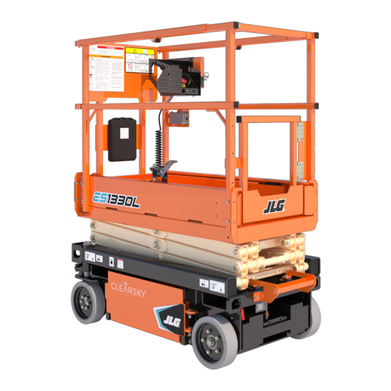
- Page 1 Operation and Safety Manual Original Instructions - Keep this manual with the machine at all times. Models ES1330L ES1530L PVC 2004 ANSI AS/NZS GB 31217186 May 26, 2020 - Rev B ®...
- Page 2 WARNING Operating, servicing and maintaining this vehicle or equipment can expose you to chemicals including engine exhaust, carbon monoxide, phthalates, and lead, which are known to the State of California to cause cancer and birth defects or other reproductive harm. To minimize exposure, avoid breathing exhaust, do not idle the engine except as necessary, service your vehicle or equipment in a well-ventilated area and wear gloves or wash your hands frequently when servicing.
- Page 3 FOREWORD FOREWORD The Mobile Elevating Work Platform (MEWP) models covered in this manual are designed and tested to meet or exceed various compliance standards. Please refer to the manufacturer’s nameplate affixed to the subject MEWP for specific standard compliance information. This manual is a very important tool! Keep it with the machine at all times.
- Page 4 SAFETY ALERT SYMBOLS AND SAFETY SIGNAL WORDS SAFETY ALERT SYMBOLS AND SAFETY SIGNAL WORDS THIS IS THE SAFETY ALERT SYMBOL. IT IS USED TO ALERT YOU TO THE POTEN- TIAL PERSONAL INJURY HAZARDS. OBEY ALL SAFETY MESSAGES THAT FOLLOW THIS SYMBOL TO AVOID POSSIBLE INJURY OR DEATH. INDICATES AN IMMINENTLY HAZARDOUS SITUATION.
- Page 5 SAFETY ALERT SYMBOLS AND SAFETY SIGNAL WORDS For: • Accident Reporting • Standards and Regulations THIS PRODUCT MUST COMPLY WITH ALL SAFETY RELATED BULLETINS. CON- Compliance Information TACT JLG INDUSTRIES, INC. OR THE LOCAL AUTHORIZED JLG REPRESENTA- • Product Safety Publica- TIVE FOR INFORMATION REGARDING SAFETY RELATED BULLETINS WHICH tions •...
- Page 6 REVISION LOG REVISION LOG Original Issue A - January 31, 2020 Revised B - May 26, 2020 31217186...
-
Page 7: Table Of Contents
TABLE OF CONTENTS SECTION - 1 - SAFETY PRECAUTIONS PRE-START INSPECTION ........2-4 WALK-AROUND INSPECTION . - Page 8 TABLE OF CONTENTS Lifting ..........3-20 Lift/Drive Selector Switch .
- Page 9 TABLE OF CONTENTS SECTION - 6 - OPERATION SPECIFICATIONS AND MAINTENANCE Wheel and Tire Replacement ......6-13 Wheel Installation.
- Page 10 TABLE OF CONTENTS LIST OF TABLES Minimum Approach Distances (M.A.D.)....1-6 Beaufort Scale (For Reference Only) ....1-7 High Drive Cutout Height.
-
Page 11: Section 1. Safety Precautions
SECTION 1 - SAFETY PRECAUTIONS SECTION 1. SAFETY PRECAUTIONS GENERAL PRE-OPERATION Operator Training and Knowledge This section outlines the necessary precautions for proper and safe machine usage and maintenance. In order to promote proper machine usage, it is mandatory that a daily routine is established based on the •... -
Page 12: Workplace Inspection
SECTION 1 - SAFETY PRECAUTIONS • Ensure that the machine is to be used in a manner which is within • This machine can be operated in nominal ambient temperatures the scope of its intended application as determined by JLG. of 0 F to 104 F (-20... -
Page 13: Operation
SECTION 1 - SAFETY PRECAUTIONS OPERATION • Always ensure that power tools are properly stowed and never left hanging by their cord from the platform work area. General • Do not assist a stuck or disabled machine by pushing or pulling except by pulling at the chassis tie-down lugs. -
Page 14: Trip And Fall Hazards
SECTION 1 - SAFETY PRECAUTIONS Trip and Fall Hazards • Prior to operation, ensure all gates and rails are fastened and secured in their proper position. • JLG Industries, Inc. recommends all personnel in the platform wear a full body harness with a lanyard attached to an authorized lan- yard anchorage point while operating this machine. -
Page 15: Electrocution Hazards
SECTION 1 - SAFETY PRECAUTIONS Electrocution Hazards • This machine is not insulated and does not provide protection from contact or proximity to electrical current. • The minimum approach distance may be reduced if insulating barriers are installed to prevent contact, and the barriers are rated •... -
Page 16: Tipping Hazards
SECTION 1 - SAFETY PRECAUTIONS • Before driving on floors, bridges, trucks, and other surfaces, check Table 1-1. Minimum Approach Distances (M.A.D.) allowable capacity of the surfaces. VOLTAGE RANGE MINIMUM APPROACH DISTANCE • Never exceed the maximum platform capacity as specified on the platform. -
Page 17: Beaufort Scale (For Reference Only)
SECTION 1 - SAFETY PRECAUTIONS DO NOT OPERATE THE MACHINE WHEN WIND CONDITIONS EXCEED SPECIFICATIONS SHOWN IN SECTION 6.2 OR AS SHOWN ON THE CAPACITY PLACARD ON THE PLAT- FORM BILLBOARD. Table 1-2. Beaufort Scale (For Reference Only) WIND SPEED BEAUFORT DESCRIPTION LAND CONDITIONS... - Page 18 SECTION 1 - SAFETY PRECAUTIONS • Never attempt to use the machine as a crane. Do not tie-off machine to any adjacent structure. Never attach wire, cable, or any similar items to platform. • If the scissor arm assembly or platform is caught so that one or more wheels are off the ground, all persons must be removed before attempting to free the machine.
-
Page 19: Crushing And Collision Hazards
SECTION 1 - SAFETY PRECAUTIONS Crushing and Collision Hazards • Always post a lookout when driving in areas where vision is obstructed. • Approved head gear must be worn by all operating and ground • Keep non-operating personnel at least 6 ft (1.8 m) away from personnel. -
Page 20: Towing, Lifting, And Hauling
SECTION 1 - SAFETY PRECAUTIONS TOWING, LIFTING, AND HAULING MAINTENANCE • Never allow personnel in platform while towing, lifting, or hauling. This sub-section contains general safety precautions which must be observed during maintenance of this machine. Additional precautions • This machine should not be towed, except in the event of emer- to be observed during machine maintenance are inserted at the appro- gency, malfunction, power failure, or loading/unloading. -
Page 21: Battery Hazards
SECTION 1 - SAFETY PRECAUTIONS Battery Hazards • Always relieve hydraulic pressure from all hydraulic circuits before loosening or removing hydraulic components. • Always disconnect batteries when servicing electrical compo- nents or when performing welding on the machine. • DO NOT use your hand to check for leaks. - Page 22 SECTION 1 - SAFETY PRECAUTIONS NOTES: 1-12 31217186...
-
Page 23: Section 2 - User Responsibilities, Machine Preparation, And Inspection
SECTION 2 - USER RESPONSIBILITIES, MACHINE PREPARATION, AND INSPECTION SECTION 2. USER RESPONSIBILITIES, MACHINE PREPARATION, AND INSPECTION PERSONNEL TRAINING Means to avoid the hazards of unprotected electrical con- ductors. The Mobile Elevating Work Platform (MEWP) is a personnel handling Selection of the appropriate MEWPs and available options device, so it is necessary that it be operated and maintained only by for the work to be performed considering specific job trained personnel. -
Page 24: Machine Familiarization
SECTION 2 - USER RESPONSIBILITIES, MACHINE PREPARATION, AND INSPECTION PREPARATION, INSPECTION, AND MAINTENANCE Machine Familiarization NOTE: Responsibilities for familiarization may vary by region. The Inspection and Maintenance table explains the machine inspec- tions and maintenance recommended by JLG Industries, Inc. Consult Only properly trained personnel who have received unit-specific famil- local regulations for further requirements for MEWPs. -
Page 25: Inspection And Maintenance Table
SECTION 2 - USER RESPONSIBILITIES, MACHINE PREPARATION, AND INSPECTION Inspection and Maintenance Table PRIMARY SERVICE TYPE FREQUENCY REFERENCE RESPONSIBILITY QUALIFICATION Before using each day; Pre-Start Inspection User or Operator User or Operator Operation and Safety Manual or whenever there’s an Operator change. Pre-Delivery Inspection Service and Maintenance Manual and Before each sale, lease, or rental delivery. -
Page 26: Pre-Start Inspection
SECTION 2 - USER RESPONSIBILITIES, MACHINE PREPARATION, AND INSPECTION PRE-START INSPECTION Walk-Around Inspection – Perform as instructed in Section 2.4. The Pre-Start Inspection should include each of the following: Battery – Charge as required. Cleanliness – Check all surfaces for leakage (oil or battery Hydraulic Oil Level –... - Page 27 SECTION 2 - USER RESPONSIBILITIES, MACHINE PREPARATION, AND INSPECTION Japan Market (Fall/Travel Restraint Only) All Other Markets 31217186...
-
Page 28: Walk-Around Inspection
SECTION 2 - USER RESPONSIBILITIES, MACHINE PREPARATION, AND INSPECTION WALK-AROUND INSPECTION Hydraulic Pump/Motor, Control Valve Installation – No unsupported wires or hoses; no damaged or broken wires. Refer to Inspection Note. Begin the Walk-Around Inspection at item 1 as noted on the Inspection Diagram. -
Page 29: Inspection Diagram
SECTION 2 - USER RESPONSIBILITIES, MACHINE PREPARATION, AND INSPECTION Inspection Diagram OAD01110 31217186... -
Page 30: Function Check
SECTION 2 - USER RESPONSIBILITIES, MACHINE PREPARATION, AND INSPECTION FUNCTION CHECK From the Platform Control Console: a. Ensure the control console is firmly secured in the Perform the Function Check as follows: proper location. b. Ensure all guards protecting switches are in place. From the Ground Control Panel with no load in the plat- form: c. -
Page 31: High Drive Cutout Height
SECTION 2 - USER RESPONSIBILITIES, MACHINE PREPARATION, AND INSPECTION g. With the platform elevated on a smooth, firm, level sur- With the platform in the stowed position: face with no overhead obstructions, drive the machine a. Drive the machine on a grade, not to exceed the rated to check if the high drive cutback speed limit is gradeability, and stop to ensure the drive motor brakes engaged at the height indicated in Table 2-1. - Page 32 SECTION 2 - USER RESPONSIBILITIES, MACHINE PREPARATION, AND INSPECTION NOTES: 2-10 31217186...
-
Page 33: Section 3 - Machine Controls, Indicators, And Operation
SECTION 3 - MACHINE CONTROLS, INDICATORS, AND OPERATION SECTION 3. MACHINE CONTROLS, INDICATORS, AND OPERATION GENERAL DESCRIPTION This machine is a Mobile Elevating Work Platform (MEWP) used to posi- NOTICE tion personnel along with their necessary tools and materials at work locations. -
Page 34: Operating Characteristics And Limitations
SECTION 3 - MACHINE CONTROLS, INDICATORS, AND OPERATION OPERATING CHARACTERISTICS AND LIMITATIONS PLATFORM LOADING Placards The platform maximum rated load capacity is shown on a placard located on the platform billboard and ground control station and is Important points to remember during operation are provided at the based upon the machine positioned on a smooth, firm surface within control stations by DANGER, WARNING, CAUTION, NOTICE, and the limits of the maximum operating slope. -
Page 35: Machine Control Locations
SECTION 3 - MACHINE CONTROLS, INDICATORS, AND OPERATION MACHINE CONTROL LOCATIONS 1. Ground Control Station 2. Platform Control Station 3. Platform Manual Descent Control (T-Handle) 4. AC Plug (for Platform AC Receptacle Outlet Box) 5. AC Plug (Battery Charger Input) 6. -
Page 36: Battery Charging
SECTION 3 - MACHINE CONTROLS, INDICATORS, AND OPERATION BATTERY CHARGING Connect the charger AC input plug to a grounded outlet using a 3 wire heavy duty extension cord. The battery charger AC input plug is located inside the frame at the rear After connecting the charger to an AC outlet at the start of of the machine. -
Page 37: Ground Control Station
SECTION 3 - MACHINE CONTROLS, INDICATORS, AND OPERATION GROUND CONTROL STATION 1. Ground/Platform/OFF Key Selector Switch 4. Hourmeter 2. Platform Lift/Lower Switch 5. Overload Indicator 3. Ground Emergency Stop Button 6. MDI Indicator (If Equipped) DO NOT OPERATE FROM GROUND CONTROL STATION WITH PERSONNEL IN THE PLAT- FORM EXCEPT IN AN EMERGENCY. -
Page 38: Ground/Platform/Off Key Selector Switch
SECTION 3 - MACHINE CONTROLS, INDICATORS, AND OPERATION Ground/Platform/OFF Key Selector Switch Ground Emergency Stop Switch The key selector switch on the A red two-position emergency stop switch when posi- Ground Control Station directs tioned to ON with the key selector switch positioned electrical power to the desired to ground furnishes operating power to the ground control station. -
Page 39: Mdi Indicator (If Equipped)
SECTION 3 - MACHINE CONTROLS, INDICATORS, AND OPERATION MDI Indicator (If Equipped) When a problem occurs and a DTC Code displayed: • A LED wrench icon (1) LED illuminates. The Multifunction Digital Indicator (MDI) displays a Battery Discharge • A three to five digit DTC code will display on the DTC LCD display Indicator (BDI), a LCD display showing the current hourmeter reading, a system distress LED, and Diagnostic Trouble Codes (DTC) when a func- (2) below the wrench icon. -
Page 40: Platform Control Station
SECTION 3 - MACHINE CONTROLS, INDICATORS, AND OPERATION PLATFORM CONTROL STATION 1. Emergency Stop Switch 2. Lift/Drive Select Switch 3. Forward/Reverse/Lift/Lower Directional Arrow 4. Steer Control Switch and Direction Decal 5. Joystick Controller 6. Trigger (Enable) Switch 7. Overload Indicator 8. - Page 41 SECTION 3 - MACHINE CONTROLS, INDICATORS, AND OPERATION 1. Emergency Stop Switch 2. Lift/Drive Select Switch 3. Forward/Reverse/Lift/Lower Directional Arrow 4. Steer Control Switch and Direction Decal 5. Joystick Controller 6. Trigger (Enable) Switch 7. Overload Indicator 8. Tilt Indicator 9.
-
Page 42: Emergency Stop Switch
SECTION 3 - MACHINE CONTROLS, INDICATORS, AND OPERATION Emergency Stop Switch Lift/Drive Selector Switch NOTE: NOTE: Both ground and platform emergency stop switches must be set When selecting between the Lift and Drive functions the joystick to ON in order to operate the machine. control must be returned to the neutral position for approxi- mately 1/2 second before the function change is operable. -
Page 43: Forward/Reverse/Lift/Lower Directional Arrow
SECTION 3 - MACHINE CONTROLS, INDICATORS, AND OPERATION Forward/Reverse/Lift/Lower Directional Steering And Traveling Arrow This decal indicates the proper direction to mount DO NOT DRIVE WITH PLATFORM RAISED EXCEPT ON A SMOOTH, FIRM SURFACE the platform control box, with the black arrow WITHIN THE LIMITS OF THE MAXIMUM OPERATING SLOPE, FREE OF OBSTRUCTIONS pointing to the front of the machine. -
Page 44: Steering
SECTION 3 - MACHINE CONTROLS, INDICATORS, AND OPERATION Steering Raising And Lowering Platform On the platform control station, position the lift/ If the machine was shut drive select switch to the drive/steer position. down, place the key selec- To steer the machine, engage trigger switch and tor switch to the platform the thumb-operated steer rocker switch on the position. -
Page 45: Overload Indicator (Lss)
SECTION 3 - MACHINE CONTROLS, INDICATORS, AND OPERATION Overload Indicator (LSS) Variable Tilt - Platform Restricted Height Indicator The Overload Indicator indicates when the plat- form has been overloaded. An audible alarm will This indicator shows the maximum allowable plat- also signal when the platform is overloaded. -
Page 46: Alarm
SECTION 3 - MACHINE CONTROLS, INDICATORS, AND OPERATION Alarm Indoor/Outdoor Operation Indicator This alarm mounted on the front of the platform control station will The Indoor (green) indicator and the Outdoor sound for various machine conditions or warnings such as system- (yellow) indicator displays the mode in which ready chirp or if the machine tilt warning is activated. -
Page 47: Platform Manual Descent
SECTION 3 - MACHINE CONTROLS, INDICATORS, AND OPERATION PLATFORM MANUAL DESCENT Use the Platform Manual Descent in the event of total power failure to lower the platform using gravity. The red T-handle is located on the left rear of the machine, just below the platform ladder. Look for the instruction decal located beside the T-handle. -
Page 48: 3.10 Grade And Sideslope
SECTION 3 - MACHINE CONTROLS, INDICATORS, AND OPERATION 3.10 GRADE AND SIDESLOPE 3-16 31217186... -
Page 49: 3.11 Platform Extension
SECTION 3 - MACHINE CONTROLS, INDICATORS, AND OPERATION 3.11 PLATFORM EXTENSION This machine is equipped with an extension deck that allows the oper- ator better access to certain work areas. The deck extension adds length to the front of the platform. FOR MAXIMUM CAPACITY OF THE DECK EXTENSION, REFER TO SECTION 6.2, OR REFER TO THE CAPACITY PLACARD ON PLATFORM BILLBOARD. -
Page 50: 3.12 Parking And Stowing Machine
SECTION 3 - MACHINE CONTROLS, INDICATORS, AND OPERATION 3.12 PARKING AND STOWING MACHINE Drive the machine to a well-protected and well-ventilated area. Ensure the platform is fully lowered. NOTICE WHEN THE MACHINE IS SHUT DOWN FOR OVERNIGHT PARKING OR BATTERY CHARGING, THE EMERGENCY STOP AND POWER SELECT SWITCHES MUST BE POSI- TIONED TO OFF TO PREVENT DRAINING THE BATTERIES. -
Page 51: Platform Rails Fold-Down Procedure
SECTION 3 - MACHINE CONTROLS, INDICATORS, AND OPERATION 3.13 PLATFORM RAILS FOLD-DOWN PROCEDURE (IF EQUIPPED) Platform with Dual Rail Extension Deck ONLY FOLD DOWN THE RAILS WHEN THE MACHINE IS IN THE STOWED (PLATFORM FULLY LOWERED) POSITION. DO NOT RAISE THE PLATFORM WITH THE RAILS FOLDED DOWN. -
Page 52: 3.14 Machine Lifting And Tie Down
SECTION 3 - MACHINE CONTROLS, INDICATORS, AND OPERATION 3.14 MACHINE LIFTING AND TIE DOWN Lifting The machine may be lifted using a forklift truck. Lift only using the built-in forklift pockets on the side of the machine and only with the platform in the stowed position. -
Page 53: Tie Down
SECTION 3 - MACHINE CONTROLS, INDICATORS, AND OPERATION Tie Down When transporting the machine, fully lower the platform (stowed posi- tion) and secure the machine to the truck or trailer deck. There are two tie-down/lift up lugs at the front of the machine and two tie-down lugs at rear of the machine. - Page 54 SECTION 3 - MACHINE CONTROLS, INDICATORS, AND OPERATION 3-22 31217186...
-
Page 55: Towing
SECTION 3 - MACHINE CONTROLS, INDICATORS, AND OPERATION 3.15 TOWING Chock wheels or secure machine with tow vehicle. Pull out the emergency stop switch and position the key- It is not recommended that this machine be towed except in the event switch to ground mode. - Page 56 SECTION 3 - MACHINE CONTROLS, INDICATORS, AND OPERATION NOTES: 3-24 31217186...
-
Page 57: Section 4 - Emergency Procedures
SECTION 4 - EMERGENCY PROCEDURES SECTION 4. EMERGENCY PROCEDURES GENERAL INFORMATION Righting of Tipped Machine A fork truck of suitable capacity or equivalent equipment should be This section explains the steps to be taken in case of an emergency sit- placed under the elevated side of the chassis, with a crane or other suit- uation during operation. -
Page 58: Platform Manual Descent
SECTION 4 - EMERGENCY PROCEDURES PLATFORM MANUAL DESCENT Use the Platform Manual Descent in the event of total power failure to lower the platform using gravity. The red T-handle is located on the left rear of the machine, just below the platform ladder. Look for the instruction decal located beside the T-handle. -
Page 59: Incident Notification
SECTION 4 - EMERGENCY PROCEDURES INCIDENT NOTIFICATION NOTICE JLG Industries, Inc. must be notified immediately of any incident FOLLOWING ANY INCIDENT, THOROUGHLY INSPECT THE MACHINE. DO NOT ELEVATE THE involving a JLG product. Even if no injury or property damage is evi- PLATFORM UNTIL IT IS CERTAIN THAT ALL DAMAGE HAS BEEN REPAIRED AND THAT ALL dent, JLG must be contacted by telephone and provided with all nec- CONTROLS ARE OPERATING CORRECTLY. - Page 60 SECTION 4 - EMERGENCY PROCEDURES NOTES: 31217186...
-
Page 61: Section 5 - Accessories
SECTION 5 - ACCESSORIES SECTION 5. ACCESSORIES AVAILABLE ACCESSORIES Market ACCESSORY ANSI ANSI Korea Japan China (USA Only) Magnetic Gate Latch Footswitch Anti-Vandalism Package ... -
Page 62: Magnetic Gate Latch
SECTION 5 - ACCESSORIES MAGNETIC GATE LATCH FOOTSWITCH OAD00120 1.Footswitch Assembly The Footswitch serves as another enable switch in the function control circuit. It must be depressed in sequence with the plat- form control joystick trigger switch to enable operation of machine functions when using the platform controls. -
Page 63: Anti-Vandalism Package
SECTION 5 - ACCESSORIES ANTI-VANDALISM PACKAGE The Anti-Vandalism Package consists of two lockable covers for the Platform and Ground Control Stations that prevent unauthorized use of the machine. Locks are not provided with this kit. Platform Control Station Ground Control Station 1. -
Page 64: Jlg™ Mobile Control
SECTION 5 - ACCESSORIES JLG™ MOBILE CONTROL Download Visit the Apple Store®, Google Play®, or The JLG Mobile Control application allows machine operators to drive https://www.JLG.com/mobilecontrol in order to download the JLG remotely from a Bluetooth® equipped hand-held mobile device. Mobile Control application. -
Page 65: Operation
SECTION 5 - ACCESSORIES Operation Download, read, and understand the JLG Mobile Control Supplement Manual from https://www.JLG.com/mobilecontrol prior to using the JLG Mobile Control. NEVER DRIVE THE MACHINE USING JLG MOBILE CONTROL WHILE STANDING IN THE PLATFORM, OR WITHOUT CLEAR LINE-OF-SIGHT BETWEEN THE MACHINE AND ITS TRAVEL PATH, AS SERIOUS INJURY COULD OCCUR TO OPERATOR OR BYSTANDER. - Page 66 SECTION 5 - ACCESSORIES NOTES: 31217186...
-
Page 67: Section 6 - Operation Specifications And Maintenance
SECTION 6 - OPERATION SPECIFICATIONS AND MAINTENANCE SECTION 6. OPERATION SPECIFICATIONS AND MAINTENANCE GENERAL INFORMATION Serial Number Identification This section of the manual provides additional necessary information to the operator for proper operation and maintenance of this machine. The maintenance portion of this section is intended as information to assist the machine operator to perform daily maintenance tasks only. -
Page 68: Machine Specifications
SECTION 6 - OPERATION SPECIFICATIONS AND MAINTENANCE MACHINE SPECIFICATIONS DESCRIPTION ES1330L ES1530L Occupied Floor Area Operating Specifications 10.98 ft (1.02 m Ground Bearing Pressure 114 psi DESCRIPTION ES1330L ES1530L Japan 119 psi 126 psi All Other Markets Gross Vehicle Weight 1,745 lb (792 kg) Max. -
Page 69: Machine Dimensions
SECTION 6 - OPERATION SPECIFICATIONS AND MAINTENANCE Machine Dimensions ES1530L DESCRIPTION (Japan) DESCRIPTION ES1330L Maximum Working Height 20.8 ft (6.3 m) Maximum Working Height 18.4 ft (5.6 m) Overall Machine Height (Stowed) 70.8 in (180 cm) Overall Machine Height (Stowed) 71.8 in (182.4 cm) Overall Machine Height (Elevated) 18.2 ft (5.55 m) -
Page 70: Platform Capacities
SECTION 6 - OPERATION SPECIFICATIONS AND MAINTENANCE Platform Capacities ES1530L DESCRIPTION (All Other Markets) DESCRIPTION ES1330L ES1530L Maximum Working Height 20.8 ft (6.3 m) 2 persons (Indoor) Overall Machine Height (Stowed) Operating Personnel 1 person 1 person (Outdoor) 70.8 in (180 cm) Fixed Rails 74.8 in (190.1 cm) Dual Rails... -
Page 71: Tires
SECTION 6 - OPERATION SPECIFICATIONS AND MAINTENANCE Tires Batteries DESCRIPTION ES1330L, ES1530L DESCRIPTION Lead Acid Size 10 in x 3 in (255 mm x 76 mm) Voltage (24V System - Series) 12V per battery Wheel Bolt Torque(M10 x 1.5 Bolt) 43 ft.lb. -
Page 72: Battery Charger
SECTION 6 - OPERATION SPECIFICATIONS AND MAINTENANCE BATTERY CHARGER Specifications Electrical System Voltage (DC) Battery Charger Delta-Q Green Power Input AC Input Voltage 85-270V AC 85-265V AC Nominal AC Input Voltage 100V AC / 240V AC RMS 120V AC / 230V AC RMS Input Frequency 50 - 60Hz 50 - 60Hz... -
Page 73: Delta-Q
SECTION 6 - OPERATION SPECIFICATIONS AND MAINTENANCE Delta-Q Green Power • Battery Charging: 7 segment display - charging percent of capac- ity, charging voltage, charging current • AC Power On: Blue LED on • Charging Percent of Capacity: "%" Red LED on •... -
Page 74: Lubrication
SECTION 6 - OPERATION SPECIFICATIONS AND MAINTENANCE LUBRICATION Specifications Lubrication SPECIFICATIONS Multipurpose Grease having a minimum dripping point of 350° F. Excellent water SPECIFICATION MOBIL DTE10 EXCEL 15 MOBIL EAL ENVIRONSYN H 32 resistance and adhesive qualities, and being of extreme pressure type. (Timken OK 40 pounds minimum.) ISO Viscosity Grade Extreme Pressure Gear Lube (oil) meeting API service classification GL-5 or MIL-... -
Page 75: Hydraulic Oil Operating Temperature Chart
SECTION 6 - OPERATION SPECIFICATIONS AND MAINTENANCE Hydraulic Oil Operating Temperature Chart 31217186... -
Page 76: Operator Maintenance
SECTION 6 - OPERATION SPECIFICATIONS AND MAINTENANCE OPERATOR MAINTENANCE Rotate prop assembly counterclockwise until it is rests on the arm proper holder plate on the side of the scissor arm assembly. Engaging the Safety Prop NEVER WORK UNDER AN ELEVATED PLATFORM UNTIL IT HAS BEEN RESTRAINED FROM MOVEMENT WITH THE SAFETY PROP, BLOCKING, OR OVERHEAD SLING. -
Page 77: Hydraulic Oil Check Procedure
SECTION 6 - OPERATION SPECIFICATIONS AND MAINTENANCE Hydraulic Oil Check Procedure Check the hydraulic oil level only when the machine is in the stowed position. Ensure the hydraulic oil has warmed to operating tempera- ture before checking the reservoir. Open the hydraulic compartment door and locate the hydraulic reservoir (1). -
Page 78: Battery Maintenance And Safety Practices
SECTION 6 - OPERATION SPECIFICATIONS AND MAINTENANCE Battery Maintenance and Safety Practices BATTERY FLUID LEVEL OF FULLY FILLER CAP CHARGED BATTERY NOTE: These instructions are for unsealed (wet) batteries only. VENT TUBE If machine is equipped with sealed batteries, no maintenance other than cleaning corroded battery terminals is required. -
Page 79: Tire Wear And Damage
SECTION 6 - OPERATION SPECIFICATIONS AND MAINTENANCE Tire Wear and Damage If any of the following is discovered during tire inspection, measures must be taken to remove the JLG product from service immediately. Arrangements must be made for replacement of the tires or tire assem- The tire and rim assemblies installed on machines have been approved blies. -
Page 80: Wheel Installation
SECTION 6 - OPERATION SPECIFICATIONS AND MAINTENANCE Wheel Installation Tighten the mounting bolts to the proper torque to prevent wheels from coming loose. Use a torque wrench to tighten. Install wheel (1) onto hub (2). Start mounting bolts (3) by hand to prevent cross threading. DO NOT use a lubricant on threads. -
Page 81: Decal Installation
SECTION 6 - OPERATION SPECIFICATIONS AND MAINTENANCE DECAL INSTALLATION 31217186 6-15... - Page 82 SECTION 6 - OPERATION SPECIFICATIONS AND MAINTENANCE 1. ANSI 2. China, Korea (Dual Rails) 3. Japan, AUS 4. CE 5. China, Korea (Fixed Rails) 6. CSA 6-16 31217186...
- Page 83 SECTION 6 - OPERATION SPECIFICATIONS AND MAINTENANCE 1. ANSI, CE, Japan, AUS 2. China 3. Korea, CSA 31217186 6-17...
-
Page 84: Decals
SECTION 6 - OPERATION SPECIFICATIONS AND MAINTENANCE Decals ENGLISH ENG/KOR ENG/CHI (GB) JAPAN ITEM (1001247301-D) (1001254501-C) (1001247302-D) (1001247303-D) (1001247304-D) (1001247305-D) (1001256628-A) 1701504 1701504 1701504 1701504 1701504 1701504 1701504 1701640 1701640 1701640 1701640 1701640 1701640 1701640 1703819 1703819 1703819 1703819 1703819 1703819 1703819 1001248126... - Page 85 SECTION 6 - OPERATION SPECIFICATIONS AND MAINTENANCE ENGLISH ENG/KOR ENG/CHI (GB) JAPAN ITEM (1001247301-D) (1001254501-C) (1001247302-D) (1001247303-D) (1001247304-D) (1001247305-D) (1001256628-A) 1703813 1704340 1707022 1704344 1705670 1705670 1001223055 1001223971 1001224048 1001224051 1001231801 1001231801 1001228370 1001228370 1001244301 1001244298 1001256675 1001256675 1001256675 1001256675 1001256675 1001256675 1001256675...
-
Page 86: Diagnostic Trouble Codes (Dtc)
SECTION 6 - OPERATION SPECIFICATIONS AND MAINTENANCE DIAGNOSTIC TROUBLE CODES (DTC) If a correction is made during a check, conclude the check by recy- cling machine power by using the emergency stop switch. IMPORTANT THE CODES LISTED IN THE FOLLOWING TABLE IS NOT A COMPLETE LISTING OF SHOULD A FAULT OCCUR THAT CANNOT BE CORRECTED BY THE OPERATOR, THE PROB- MACHINE DTC. - Page 87 SECTION 6 - OPERATION SPECIFICATIONS AND MAINTENANCE Flash Help Message Alarm Action Trigger Code 001 EVERYTHING OK None None · No Motion restrictions • Platform Mode and no Faults are active. 002 GROUND MODE OK None None · No Motion restrictions •...
- Page 88 SECTION 6 - OPERATION SPECIFICATIONS AND MAINTENANCE Flash Help Message Alarm Action Trigger Code 009 DRIVE PREVENTED – ELEVATED ABOVE None None • DriveState = PREVENTED • The Drive Cutout functionality is enabled, and the Platform is Elevated DRIVE CUTOUT HEIGHT above the Calibrated Cutout Height.
- Page 89 SECTION 6 - OPERATION SPECIFICATIONS AND MAINTENANCE Flash Help Message Alarm Action Trigger Code 225 FUNCTION PROBLEM – STEER RIGHT PER- None • DriveState = PREVENTED • Steer Right Switch in the Platform Control Box was closed during power- MANENTLY SELECTED up.
- Page 90 SECTION 6 - OPERATION SPECIFICATIONS AND MAINTENANCE Flash Help Message Alarm Action Trigger Code 255 PLATFORM OVERLOADED PF: 5000ms ON/ • Drive and Lift Restrictions • While the Load Sensing System is enabled, the Platform Load measured by 2000ms OFF the Load Sensing System is excessive.
- Page 91 SECTION 6 - OPERATION SPECIFICATIONS AND MAINTENANCE Flash Help Message Alarm Action Trigger Code 4235 POWER MODULE TOO HOT - REDUCED None • DriveState =CREEP • Heatsink temperature exceeded 185° F (85° C). OPERATION • LiftUpState = CREEP • Effect: Reduced drive and brake torque. •...
- Page 92 SECTION 6 - OPERATION SPECIFICATIONS AND MAINTENANCE Flash Help Message Alarm Action Trigger Code 4424 POWER MODULE VOLTAGE TOO LOW - MOD- None • DriveState = PREVENTED • Severe B+ Undervoltage Set: Capacitor bank voltage dropped below ULE SHUTDOWN • LiftUpState = PREVENTED Severe Undervoltage limit with FET bridge enabled.
-
Page 93: Supplemental Information
SECTION 6 - OPERATION SPECIFICATIONS AND MAINTENANCE SUPPLEMENTAL INFORMATION The following information is provided in accordance with the require- ments of the European Machinery Directive 2006/42/EC and is only applicable to CE machines. For electric powered machines, the equivalent continuous A-Weighted sound pressure level at the work platform is less than 70dB(A). - Page 94 SECTION 6 - OPERATION SPECIFICATIONS AND MAINTENANCE NOTES: 6-28 31217186...
- Page 95 SECTION 7 - INSPECTION AND REPAIR LOG SECTION 7. INSPECTION AND REPAIR LOG Machine Serial Number _______________________________________ DATE COMMENTS 31217186...
- Page 96 SECTION 7 - INSPECTION AND REPAIR LOG DATE COMMENTS 31217186...
- Page 98 Corporate Office JLG Industries, Inc. 1 JLG Drive McConnellsburg, PA 17233-9533 USA (717) 485-5161 (Corporate) (877) 554-5438 (Customer Support) (717) 485-6417 Visit our website for JLG Worldwide Locations. www.jlg.com...
Need help?
Do you have a question about the JLG ES1330L and is the answer not in the manual?
Questions and answers