BendPak HD-14T Installation And Operation Manual
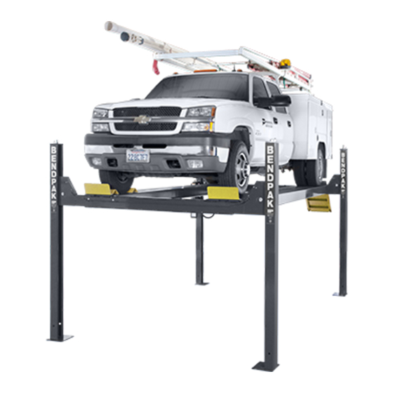
14,000 pound capacity commercial grade four-post lifts
Hide thumbs
Also See for HD-14T:
- Installation and operation manual (76 pages) ,
- Service manual (35 pages)
Table of Contents
Advertisement
Quick Links
INSTALLATION AND OPERATION MANUAL
14,000 POUND CAPACITY
COMMERCIAL GRADE
FOUR-POST LIFTS
MODELS:
HD-14T
VERSION D
Keep this operation manual near the
machine at all times. Make sure that
ALL USERS read this manual.
RECEIVING
The shipment should be thoroughly inspected as soon as it is
received. The signed Bill of Lading is acknowledgement by
the shipping carrier as receipt of this product as listed in your
invoice as being in a good condition of shipment. If any of
these goods listed on this Bill of Lading are missing or dam-
aged, do not accept goods until the shipping carrier makes a
notation on the freight bill of the missing or damaged goods.
Do this for your own protection.
PLEASE READ THE ENTIRE CONTENTS OF THIS MANUAL PRIOR TO
INSTALLATION AND OPERATION. BY PROCEEDING YOU AGREE THAT
YOU FULLY UNDERSTAND AND COMPREHEND THE FULL CONTENTS OF
THIS MANUAL. FORWARD THIS MANUAL TO ALL OPERATORS. FAILURE TO
OPERATE THIS EQUIPMENT AS DIRECTED MAY CAUSE INJURY OR DEATH.
BE SAFE
Your new lift was designed and built with safety in mind.
However, your overall safety can be increased with proper
training and thoughtful operation on the part of the operator.
DO NOT operate or repair this equipment without reading this
manual and the important safety instructions shown inside.
Keep this operation manual near the lift at all times. Make sure
that ALL USERS read and understand this manual.
Manual REV E 09-10-14
p/n 5900037
1645 Lemonwood Dr.
Santa Paula, CA. 93060, USA
Toll Free 1-800-253-2363
Tel: 1-805-933-9970
Fax: 1-805-933-9160
www.bendpak.com
Advertisement
Table of Contents

Subscribe to Our Youtube Channel
Related Manuals for BendPak HD-14T


Summary of Contents for BendPak HD-14T
- Page 1 Manual REV E 09-10-14 p/n 5900037 INSTALLATION AND OPERATION MANUAL 14,000 POUND CAPACITY COMMERCIAL GRADE FOUR-POST LIFTS MODELS: HD-14T VERSION D Keep this operation manual near the machine at all times. Make sure that ALL USERS read this manual. RECEIVING BE SAFE The shipment should be thoroughly inspected as soon as it is Your new lift was designed and built with safety in mind.
-
Page 2: Warranty / Serial Number Information
Our comprehensive product warranty means more than a commitment to you; it’s also a commitment to the value of your new BendPak lift. For full warranty details and to register your new lift contact your nearest BendPak dealer or visit http:/ / www.bendpak.com/ support/ warranty/... -
Page 3: Definitions Of Hazard Levels
Our willingness to practices which may result in minor personal injury, assist in helping you process your claim does not make product or property damage. BendPak responsible for collection of claims or replacement of lost or damaged materials. -
Page 4: Table Of Contents
TABLE OF CONTENTS Contents Page No. Warranty / Serial Number Information ......... . .2 Definitions of Hazard Levels . -
Page 5: Installer Operator/ Protective Equipment
I understand that Bendpak lifts are designed to be installation and operation activities. installed in indoor locations only. Failure to follow... -
Page 6: Introduction
INTRODUCTION 1. Carefully remove the crating and packing 2. Check the voltage, phase and proper amperage materials. CAUTION! Be careful when cutting steel requirements for the motor shown on the motor plate. banding material as items may become loose and fall caus- Wiring should be performed by a certified electrician only. -
Page 7: Tools Required
LIFT MODEL CONCRETE REQUIREMENTS HD-14T 4” Min. Thickness / 3,000 PSI 4. OPERATING TEMPERATURE. Operate lift only between temperatures of 41° -104° F. 5. Lift is designed for INDOOR INSTALLATION ONLY. -
Page 9: Floor Plan / Specifications
FLOOR PLAN *IMPORTANT NOTE* Check Diagonal Measurements To Ensure Square Layout Diagonal Measurements Must Be Equal. MODEL HD-14T Lifting Capacity 14,000lbs / 6350 Kg. Max Capacity Front Axle 7,000 lbs. / 3175 Kg. Max Capacity Rear Axle 7,000 lbs. / 3175 Kg. -
Page 10: Clearances
CLEARANCES HD LIGHT DUTY 54in 24in 1372mm 610mm MINIMUM TO MINIMUM TO NEAREST BAY NEAREST WALL OR OBSTRUCTION APPROACH B. Place target on floor at column positions (NOT 1. Lift Location: Use architects plan and Engineers on column base plates) and record readings. automatic level (transit) when available to locate lift. -
Page 11: Power Unit Location
POWER UNIT LOCATION IMPORTANT NOTE The Power Unit can be located at either For the remainder of this instruction we will “X” location shown below. It is important to illustrate the Power Unit mounted at the locate the POWERSIDE Runway (with Cyl- DRIVER-SIDE (LEFT) FRONT Column - TOP inder) on the SAME SIDE as the power unit ILLUSTRATION. -
Page 12: Step 3 / Column And Cross Tube Installation
A maximum shim thickness Fig 3.5 of 2” is possible by ordering optional Shim Plates. Contact your authorized BendPak Distributor for ordering information. 3. Using a forklift or crane, raise the Cross Tubes (making sure the Plastic Slide Blocks are still in position) and drop down into the top of the Columns. -
Page 13: Step 4 / Raising The Cross Tubes
5. The Columns and Cross Tubes will now be in position 2. Manually raise the Cross Tubes until the Primary and spaced properly for the runways. Safety Locks engage and rest on the third or fourth lock position or approximately 24” off the ground. It is impor- 6. -
Page 14: Step 5 / Powerside Runway Installation
STEP 5 Fig 5.4 ( Powerside Runway Installation ) 1. Locate the Powerside Runway easily identified by the Cylinder and sheave roller mounting structures welded on the underside. The Powerside Runway will be positioned on the side of the lift where the power unit is installed. (See Fig. -
Page 16: Step 7 / Cable Sheave Installation
STEP 7 ( Cable / Sheave Installation ) 1. Inspect Cables to insure proper lengths. All Cables DANGER! should have ID tags showing proper Cable lengths. Failure to route lifting cables as described may lead to serious personal injury and/or death to operator or 2. -
Page 17: Step 9 / Power Unit Installation
STEP 9 Fig 8.3 ( Power Unit Installation ) . Mount the Power Unit, the Flex Tube Mount- ing Bracket, the Vibration Dampener and the Air Valve Mounting Bracket to the Power Unit Mounting Bracket us- ing the M8 hex bolts and nylock nuts then fill the reservoir with 12 quarts of 10-WT hydraulic oil or Dexron III auto- matic transmission fluid. -
Page 18: Step 10 / Routing Hydraulic Hoses
The standard Power Unit for your lift is 220 volt, 60HZ, single phase. All wiring must be performed by a certified electrician only. SEE WIRING INSTRUCTIONS AFFIXED TO MOTOR FOR PROPER WIRING INSTRUCTIONS. WARNING ! DO NOT run Power Unit with no oil. Damage to pump can occur. The Power Unit must be kept dry. - Page 19 Fig 10.5 90° Air Line Compression Fitting 90° Air Line Compression Fitting 90° O-Ring Fitting 5. Route both the Power Unit Hydraulic Hose and TWO (2) lengths of Air Line through the Flex Hose. (See Fig. 10.6) Fig 10.6 2. Remove the captive nut on the Compression Fitting. Insert the Plastic Air line through the alignment sleeve and into the end of the fitting until it bottoms out.
-
Page 20: Step 11 / Routing Air Lines
7. Connect the hydraulic hose and air line as shown below STEP 11 making sure the hydraulic hose passes through the retain- ( Routing Air Lines) ing rings. MAKE SURE HOSES ARE KEPT CLEAR OF CABLES. There will be one air line hose left unconnected in 1. -
Page 21: Safety Airline Routing
SAFETY AIR LINE ROUTING NOTE: CUT THE PROVIDED 1/4” AIR LINE TUBING WITH A SHARP BLADE TO LENGTHS AS REQUIRED. TUBING MUST BE CUT SQUARE WITH ALL PLASTIC BURRS REMOVED. AIR TUBING ASSEMBLY: SEE PAGE 19 FOR ASSEMBLY OF AIR LINE TUBING INTO FITTING. CAUTION: REMOVING THE AIR TUBING FROM THE COMPRESSION FITTINGS WILL CAUSE DAMAGE TO THE TUBING ITSELF. - Page 22 DANGER! DO NOT PERFORM ANY MAINTENANCE OR INSTALLATION OF ANY COMPONENTS WITH OUT FIRST ENSURING THAT ELECTRICAL POWER HAS BEEN DISCONNECTED AT THE SOURCE OR PANEL AND CANNOT BE RE-ENERGIZED UNTIL ALL MAINTENANCE AND/OR INSTALLATION PROCEDURES ARE COMPLETED. IMPORTANT POWER-UNIT INSTALLATION NOTES n DO NOT run power unit with no oil.
-
Page 24: Step 12 / Power Unit Hook Up
STEP 12 STEP 13 ( Power Unit Hook Up ) ( Inspecting The Slack Safety Springs ) 1. Have a certified electrician run the power supply to motor. Refer to the data plate found on the motor for proper power supply and wire size. The following steps involve the SLACK CABLE SAFETY DEVICE and MAIN SAFETY. -
Page 25: Step 15 / Anchoring The Columns
Continue pressing the raise button until the Cables IMPORTANT NOTE: get taught and the lift starts to move. BendPak lifts are supplied with installation Raise lift until the lift stops and lower until the safe- instructions and concrete fasteners meeting the criteria as prescribed by the American National ties engage the top locking position. -
Page 26: Step 16 / Attaching Approach Ramps / Tire Stops
STEP 16 (Attaching the Approach Ramp /Tire Stops) 1. Install the Approach Ramps on the entry side of ALWAYS WEAR SAFETY GOGGLES. the lift using the Top Pin Tube. (See Fig. 16.1) 4. Assemble the Washers and Nuts on the Anchors then tap each hole with a hammer until the washer rests Fig 16.1 against Base Plate. -
Page 27: Step 17 / Leveling System
STEP 17 Fig 17.2 (Leveling / Synchronizing) 1. Using an engineer’s automatic Level (transit), locate the Level, at a convenient location in the shop that allows an unobstructed view of all four corners of the runways. Fig 17.1 11. Next, load vehicle onto the lift. 12. -
Page 28: Optional Equipment Installation
HD-9-12X-14 Rolling Jack Air Line Kit Installation Part # 5174009 REV 01-06-09... - Page 29 Adapter Plate Required for HD-9,12,14 Adapter Plate Required for HD-9,12,14...
-
Page 30: Step 19 / Operation/ Maintenance
Use only qualified lift ser- ALI ALOIM-2000, American National Standard for Automo- vice personnel and genuine BendPak parts to make repairs. tive Lifts-Safety Requirements for Operation, Inspection and Maintenance; and The Employer shall ensure that lift inspectors are qualified and that they are adequately trained in the inspection of the lift. - Page 31 • THOROUGHLY train all employees in use and care of lift, 5. After vehicle is raised to the desired height, lower the using manufacturer’s instructions and “Lifting It Right” and lift onto the nearest Safety Lock. Do not allow Cables to “Safety Tips”...
- Page 32 2. Check safety locks to ensure they are in good operating condition. 3. Check cables and sheaves for wear. Replace worn parts as required with genuine BendPak parts. 4. Inspect adapters for damage or excessive wear. Re- place as required with genuine BendPak parts.
- Page 33 WIRE ROPE INSPECTION AND MAINTENANCE Lifting cables should be replaced every three - five years or when visible signs of damage are apparent. DO NOT USE LIFT WITH DEFECTIVE / WORN CABLES. Lifting cables should be maintained in a well-lubricated condition at all times. Wire rope is only fully protected when each wire strand is lubricated both internal and external.
- Page 36 Safe Lift Operation Automotive and truck lifts are critical to the operation and profitability of your business. The safe use of this and other lifts in your shop is critical in preventing employee injuries and damage to customer’s vehicles. By operating lifts safely you can insure that your shop is profitable, productive and safe.
- Page 37 DO NOT leave the controls while the lift is still in motion. DO NOT stand directly in front of the vehicle or in the bay when vehicle is being loaded or driven into position. DO NOT Go near vehicle or attempt to work on the vehicle when being raised or lowered. REMAIN CLEAR of lift when raising or lowering vehicle.
-
Page 38: Troubleshooting Guide
LIFT WILL NOT RAISE POSSIBLE CAUSE 1. Air in oil, (1,2,8,13) 2. Cylinder binding, (9) 3. Cylinder leaks internally, (9) 4. Motor run backward under pressure, (11) 5. Lowering valve leaks, (3,4,6,10,11) 6. Motor runs backwards, (7,14,11) 7. Pump damaged, (10,11) 8. - Page 39 MOTOR WILL NOT RUN POSSIBLE CAUSE Fuse blown, (5,2,1,3,4) Limit switch burned out, (1,2,3,4) Microswitch burned out, (1,2,3,4) Motor burned out, (1,2,3,4,6) Voltage to motor incorrect, (2,1,8) REMEDY INSTRUCTION Check for correct voltage ......Compare supply voltage with voltage on motor name tag.
- Page 40 WILL NOT RAISE LOADED LIFT POSSIBLE CAUSE 1. Air in oil, (1,2,3,4) 2. Cylinder binding, (5) 3. Cylinder leaks internally, (5) 4. Lift overloaded, (6,5) 5. Lowering valve leaks, (7,8,1,5,9) 6. Motor runs backwards, (10,12,9) 7. Pump damaged, (5,9) 8. Pump won’t prime, (1,2,3,4,5,11,9) 9.
- Page 41 LIFT WILL NOT STAY UP POSSIBLE CAUSE 1. Air in oil, (1,2,3) 2. Check valve leaks, (6) 3. Cylinders leak internally, (7) 4. Lowering valve leaks, (4,5,1,7,6) 5. Leaking fittings, (8) REMEDY INSTRUCTION 1. Check oil level ........The oil level should be up to the bleed screw in the reservoir with the lift all the way down.
- Page 42 Grease Port / Lubrication Locations Lubricate Once A Week Torque Recommendations VALUES ARE STATED IN FOOT POUNDS (ft-lb) SAE 0-1-2 SAE Grade 5 SAE Grade 8 SOCKET HEAD CAP SCREW CLASS 4.8 CLASS 8.8 CLASS 10.9 CLASS 12.9 Bolt Size Bolt Size (SAE) (Metric)
- Page 43 MAINTENANCE RECORDS ____________________________________________________________________ ____________________________________________________________________ ____________________________________________________________________ ____________________________________________________________________ ____________________________________________________________________ ____________________________________________________________________ ____________________________________________________________________ ____________________________________________________________________ ____________________________________________________________________ ____________________________________________________________________ ____________________________________________________________________ ____________________________________________________________________ ____________________________________________________________________ ____________________________________________________________________ ____________________________________________________________________ ____________________________________________________________________ ____________________________________________________________________ ____________________________________________________________________ ____________________________________________________________________ ____________________________________________________________________...
- Page 49 This page intentionally left blank.
- Page 50 This page intentionally left blank.
- Page 51 This page intentionally left blank.
- Page 52 For Parts Or Service Contact: BendPak Inc. / Ranger Products 1645 Lemonwood Dr. Santa Paula, CA. 93060 Tel: 1-805-933-9970 Toll Free: 1-800-253-2363 Fax: 1-805-933-9160 www.bendpak.com p/n 5900037...
Need help?
Do you have a question about the HD-14T and is the answer not in the manual?
Questions and answers