
Related Manuals for Atop SW5502C


Summary of Contents for Atop SW5502C
- Page 1 SW5502C User Manual V 1.2 Wireless Serial Server Atop Technologies, Inc. SW5501C SW5502C Wireless Serial Server User Manual V1.2 April 20 , 2017...
- Page 2 This PDF Document contains internal hyperlinks for ease of navigation. For example, click on any item listed in the Table of Contents to go to that page. Published by: Atop Technologies, Inc. 2F, No. 146, Sec. 1, Tung-Hsing Rd, 30261 Chupei City, Hsinchu County Taiwan, R.O.C.
- Page 3 Wireless Serial Server Important Announcement The information contained in this document is the property of Atop Technologies, Inc., and is supplied for the sole purpose of operation and maintenance of Atop Technologies, Inc., products. No part of this publication is to be used for any other purposes, and it is not to be reproduced, copied, disclosed, transmitted, stored in a retrieval system, or translated into any human or computer language, in any form, by any means, in whole or in part, without the prior explicit written consent of Atop Technologies, Inc.,...
-
Page 4: Table Of Contents
SW5502C User Manual V 1.2 Wireless Serial Server Table of Contents Preface ..........................10 Purpose of the Manual ........................10 Who Should Use This User Manual ....................10 Supported Platform ..........................10 Warranty Period ........................... 10 Manufacturers Federal Communication Comm. Declaration of Conformity Statement ....10 European Community, Switzerland, Norway, Iceland, and Liechtenstein ........ - Page 5 SW5502C User Manual V 1.2 Wireless Serial Server 4.8.4 COM DataLog ............................56 Web configuration – System Setup....................57 4.9.1 Date/Time Settings ..........................57 4.9.2 Admin Settings ............................ 58 4.9.3 Firmware upgrade ..........................59 4.9.4 Backup/Restore Settings ........................59 4.9.5 Management List..........................60 4.9.6 Ping ..............................
- Page 6 Figure 3.1 Panel of SW5501C ............................16 Figure 3.2 Panel of SW5502C Figure 3.3 Panel of SW5502C-TB .............. 16 Figure 4.1 User Interface of Device Management© lists a SW550XC device in wireless client mode....21 Figure 4.2 Administrator Login ............................. 22 Figure 4.3 Notification in case that the SW550XC device is in different subnetwork from your PC .......
- Page 7 SW5502C User Manual Preface Wireless Serial Server Figure 4.19 Wireless Status page shows current information of SW550XC............. 32 Figure 4.20 Transition page during the gathering of surrounding wireless network information......33 Figure 4.21 Results of a Site Monitoring of SW550XC Series..................33 Figure 4.22 Network Settings Page (Wireless Client Mode) ..................
- Page 8 Table 7.4 Interpretation of SW550XC’s Operation via Front Panel LEDs ..............108 Table 7.5 Dip Switch Functions of SW5501C ......................108 Table 7.6 Dip Switch Function of SW5502C ......................108 Table 7.7 Wireless Interface Specification of SW550XC Series ................109...
- Page 9 SW5502C User Manual Preface Wireless Serial Server Table 7.8 Operating Frequencies in Different Regions at 2.4GHz ................109 Table 7.9 Supported Data Rate for Wireless Interface under IEEE 802.11 Standards ..........109 Table 7.10 Maximum Output Power of Wireless Interface under IEEE 802.11Standards ........110 Table 7.11 Receiver Sensitivity of Wireless Interface under IEEE 802.11 Standards ..........
-
Page 10: Preface
SW5502C User Manual Preface Wireless Serial Server 1 Preface Purpose of the Manual This manual supports you during the installation and configuring of the SW550XC Industrial Wireless Serial Device Server Series only. It explains some technical options available with the mentioned product. As such, it contains some advanced network management knowledge, instructions, examples, guidelines and general theories designed to help users manage this device and its corresponding software. -
Page 11: European Community, Switzerland, Norway, Iceland, And Liechtenstein
This device also conforms to the EMC requirements of the Medical Devices Directive 93/42/EEC. Note : This equipment is intended to be used in all EU and EFTA countries. Outdoor use may be restricted to certain frequencies and/or may require a license for operation. For more details, contact Atop Technologies, Inc. -
Page 12: Ul Notice For Power Supplier
SW5502C User Manual Preface Wireless Serial Server European Union This system has been evaluated for RF exposure for Humans in reference to the ICNIRP (International Commission on Non-Ionizing Radiation Protection) limits. The evaluation was based on the EN 50385 Product Standard to... -
Page 13: Introduction
Supported interfaces of serial devices include RS- 232, RS-422, and RS-485. The device supports D-sub9 or TB5 combo serial port (SW5502C). As an example, user can connect serial devices to a Wireless Serial Device Server (SW550xC) and control them through Wireless Networking Device such as wireless access point (AW5500C) in wireless local area network (WLAN). -
Page 14: Features
Wireless Serial Server Features The SW550xC Series device is the latest addition to Atop Industrial Wireless products. Its small size but powerful architecture makes it a perfect choice for industrial/manufacturing needs in which size is a decisive factor. It rewards our customers with superb connectivity withstanding all the harshness in your environment of choice. -
Page 15: Getting Started
2.4G gain: 2dBi antenna 9-pin plug of the D-Sub connector family Terminal Block 5-pin 5.08mm lockable Terminal Block x 1 (SW5501C only) 5-pin 5.08mm lockable Terminal Block x 2 (SW5502C-TB only) Documentation Hardware Installation Guide (Warranty Card is included) Mounting Kit... -
Page 16: Ordering Information
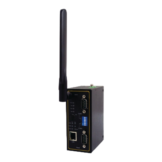
Figure 3.4 and Figure 3.5, respectively. Note that the detailed description of LEDs and DIP switch on the front panel can be found in Chapter 7.1 below. Figure 3.2 Panel of SW5502C Figure 3.3 Panel of SW5502C-TB... - Page 17 SW5502C User Manual Getting Started Wireless Serial Server Figure 3.4 Power Panel of all SW550XC Series Note: The DIP switch on the front panel of SW550xC can be used to adjust different values for pull-high or pull-low termination resistors on the RS-485 COM ports. If the RS-485 network range is shorter than 100 meters, the termination resistors are not required (by setting the DIP switch to termination off).
-
Page 18: Serial Pin Assignments
First time installation Before installing the device, please adhere to all safety procedures described below, Atop will not be held liable for any damages to property or personal injuries resulting from the installation or overall use of the device. Do not... - Page 19 SW5502C User Manual Getting Started Wireless Serial Server SW550XC in the Hardware Installation Guide. 3. Plug the power source to the unit, starting from the ground (It is a screw close to the power terminal block.) and then the 3-Pin power terminal block on the power panel in Figure 3.. A recommended power adapter (such as US315-1212 power adapter listed in Table 3.2) with 3-Pin terminal block can be connected to the...
-
Page 20: Factory Default Settings
SW5502C User Manual Getting Started Wireless Serial Server Factory Default Settings Upon arrival, the device is set with factory default settings. The SW550XC Series comes with two different IP addresses for LAN and WLAN as shown below. Table 3.4 Factory Default Network Settings... -
Page 21: Configuration And Setup
(i.e. 10.0.50.XXX) as the default IP address of the LAN connection (i.e. 10.0.50.100). Note: in the Figure below the SW5502C device appears with two lines because it has been set to operate in wireless client mode as two different IP addresses and MAC addresses are available. If, otherwise, SW5502 is set to operate in AP client mode, it will show up on the Device Management with only one IP address and MAC address. -
Page 22: Figure 4.2 Administrator Login
SW5502C Configuration and User Manual Wireless Serial Server setup Note: the default username is “admin” and the password is “default”, see Factory Defaults for more information), then click “Login” button as shown in the figure below. Figure 4.2 Administrator Login A pop-up window as shown will notify you if your personal computer and the SW550XC device are on different sub- network. -
Page 23: Figure 4.5 Mark Of Login Device In The Caution Column
SW5502C Configuration and User Manual Wireless Serial Server setup Figure 4.5 Mark of login device in the Caution column If the device cannot be login, the system will notify you with the notification in Figure 3.6. If this happens, the user should try to check the reachability between your PC and the SW550XC with ‘ping’... -
Page 24: Figure 4.8 Pop-Up Windows Of Network Setting
SW5502C Configuration and User Manual Wireless Serial Server setup Figure 4.8 Pop-up Windows of Network Setting You may proceed then to change the IP address, Subnet mask, and Gateway, and Host name of SW550XC to avoid any IP address conflict with other hosts on your LAN or to connect the device to your existing LAN as shown in Figure 3.8. -
Page 25: Figure 4.10 Waiting Notification For Restarting Device
SW5502C Configuration and User Manual Wireless Serial Server setup Figure 4.10 Waiting Notification for Restarting Device A DHCP server can automatically assign the IP address, the Subnet Mask, and the Gateway (your network gateway) of the LAN interface of SW550XC device. You can simply check “ DHCP ( Obtain an IP Automatically) ” box in the Network Setting dialog as shown in Figure 3. -
Page 26: Advanced Configuration Via Web Interface
SW5502C Configuration and User Manual Wireless Serial Server setup Advanced configuration via Web Interface The SW550XC Series’ user interface is designed intuitively for satisfying customers’ ease of use needs. Every SW550XC device is equipped with a built-in web server. It can be accessed by using a web browser for configuring by entering the device’s IP address (the default IP address is 10.0.50.100) in the URL field of your web... -
Page 27: Figure 4.13 Menu-Tree Of All Available Modes And Options Of Sw550Xc Series
SW5502C Configuration and User Manual Wireless Serial Server setup On the left side of the screen, a menu-tree is listed with all available modes and options as shown Figure 4.13. On the right side of the screen, the contents of each mode/option will be displayed in a graphical format. For more information on each selection, please refer to each corresponding section throughout this manual. -
Page 28: Operation Mode
SW5502C Configuration and User Manual Wireless Serial Server setup 4.2.1 Operation Mode The SW550XC Serial Device Server Series has been designed as a Wireless Client with the ability to choose a connection between Wireless Local Area Network (WLAN) and Local Area Network (LAN). It can also operate as an AP (access point) client, which will bridge a connection from WLAN to LAN or vice versa. -
Page 29: Figure 4.15 Waiting Message
SW5502C Configuration and User Manual Wireless Serial Server setup Figure 4.15 Waiting Message If you only want to save the settings and restart the device to a selection of Operation Mode, you can click “Apply” button to apply the setting and reboot the SW550XC device. Note that after clicking the “Apply” button, the user will briefly see the same pop-up window as in above and after a few second another pop-up window will appear as shown below. -
Page 30: Figure 4.17 Ap Client Operation Mode Setting
SW5502C Configuration and User Manual Wireless Serial Server setup Figure 4.17 AP Client Operation Mode Setting... -
Page 31: Overview
Overview The “Overview” submenu under the “System Status” menu, displays overall and current general information on the SW550XC device’s status and settings. An example of SW5502C’s Overview page is shown below. Figure 4.18 Overview Information Page of an SW550XC Device Information under the Device Information box displays the Model Name, the Device Name, Kernel Version ... -
Page 32: Wireless Status
SW5502C Configuration and User Manual Wireless Serial Server setup device. The firmware version of your SW550XC consists of the Kernel Version and the AP Version. Information under the Network Information box shows the summary of both LAN and WLAN interfaces. For ... -
Page 33: Figure 4.20 Transition Page During The Gathering Of Surrounding Wireless Network Information
SW5502C Configuration and User Manual Wireless Serial Server setup Figure 4.20 Transition page during the gathering of surrounding wireless network information. An example of a list of nearby WLAN APs which is reported by the Site Monitor is shown in Below figure. -
Page 34: Web Configuration - Network Settings
SW5502C Configuration and User Manual Wireless Serial Server setup Web configuration - Network settings The SW550XC series have the ability to utilize dual connections, i.e., WLAN and LAN at the same time. The user can configure both LAN and WLAN interfaces in this section. An example of Network Settings page for SW550XC in Wireless Client mode is shown below. -
Page 35: Figure 4.23 Network Settings Page For Bridged Interface (Ap Client Mode)
SW5502C Configuration and User Manual Wireless Serial Server setup b. Manual Settings – If the user wants to fix the IP address of LAN interface, the desired IP Address, Subnet Mask, and Default Gateway should be entered in this section. -
Page 36: Web Configuration - Wireless Settings
SW5502C Configuration and User Manual Wireless Serial Server setup 4) DNS Server Part: To allow your SW550XC device to properly connect to the Internet and be able to resolve for a host over the Internet, you must specify Preferred DNS ) Domain Name Server( and )optionally (Alternate DNS in this part . -
Page 37: Figure 4.25 Basic Setting List Webpage After Clicking Add Button
SW5502C Configuration and User Manual Wireless Serial Server setup Figure 4.25 Basic Setting List Webpage after Clicking Add Button Figure below shows an example of enabled Wireless Profile in which an AP List consists of ten available entires for network names or SSIDs. Each entry will have its number (No.) on the list and Name. Color of the Name is used to indicate the current status of the SSID or profile on the list. -
Page 38: Figure 4.26 Wireless Profile Page
SW5502C Configuration and User Manual Wireless Serial Server setup Figure 4.26 Wireless Profile Page... -
Page 39: Basic Settings
SW5502C Configuration and User Manual Wireless Serial Server setup 4.4.2 Basic Settings To set up a wireless connection for SW550XC, a number of parameters are needed to be configured in this section. However, the user will have two different wireless configuring pages when Wireless Profile (see previous subsection) is enabled as shown in previous paragraph and when Wireless Profile is disabled as shown in Figure below. -
Page 40: Figure 4.28 Basic Settings For Wireless Connection When Wireless Profile Is Disabled
SW5502C Configuration and User Manual Wireless Serial Server setup Figure 4.28 Basic Settings for Wireless Connection when Wireless Profile is Disabled. After the user finished setting the Basic Settings as shown above, please click the Save & Apply button to save the new wireless configuration on the SW550XC and allow the configuration to take effect. - Page 41 SW5502C Configuration and User Manual Wireless Serial Server setup SSID: This specifies the SSID (or network name) that SW550XC should connect to wirelessly. There is a “Scan Network” button on the right of the empty text box. This button makes it possible to look for nearby available wireless networks to attach to.
-
Page 42: Figure 4.29 Results Of Network Scanning When Uses "Scan Network" Buttons
SW5502C Configuration and User Manual Wireless Serial Server setup Steps to Connect to an Access Point You can manually enter the SSID of the connecting access point in the SSID option or use the “scan network” button to have SW550XC grab the necessary wireless information of surrounding access points in the device’s coverage area. -
Page 43: Advanced Settings
Fast Handoff – This option enables Atop’s proprietary protocol to speed up roaming between AW5500Cs (Atop’s Industrial Wireless Serial Device Servers) in addition to Fast Roaming (next option). Enable this option to allow AW5500C to share its neighboring AW5500C information to SW550XC to further reduce its roaming time. -
Page 44: Figure 4.32 Wireless Advanced Settings Page When Wireless Profile Is Enabled
SW5502C Configuration and User Manual Wireless Serial Server setup in the user’s network to prevent network loops by setting up the Forward Delay time. When disabled, SW550XC will not forward STP Bridge Protocol Data Units (BPDUs). Note that if Wireless Profile or Ad-hoc mode (Paragraph 4.4.1 above) feature is enabled, Fast Handoff, Fast Roaming and Roaming Threshold, and STP options will not be presented and supported, as shown below. -
Page 45: Web Configuration - Serial
SW5502C Configuration and User Manual Wireless Serial Server setup Web configuration – Serial 4.5.1 COM Port Overview Since details on Link Mode connectivity protocols and its settings of SW550XC series are given in the Link Modes and Applications in Chapter 5, this section will only focus on the Serial Settings only. Figure below shows an example of the COM 1 Port Settings where the upper part is dedicated for Link Mode settings and the lower part is dedicated for Serial Settings. -
Page 46: Com Configuration
SW5502C Configuration and User Manual Wireless Serial Server setup 4.5.2 COM Configuration Figure below shows the Serial Settings part of COM port settings. Note that these settings need to match the parameters on serial port of the serial device. Each option is later on described in detail. -
Page 47: Com Configuration: Advanced Settings
SW5502C Configuration and User Manual Wireless Serial Server setup 4.5.3 COM Configuration: Advanced Settings For advanced details of COM port setting, click on Advanced Settings button at the end of Serial Settings page. It will open another web browser window as shown below. Description of each option is explained as follows. - Page 48 SW5502C Configuration and User Manual Wireless Serial Server setup TCP timeout: By clicking the Enable box of TCP Timeout and input value in seconds between 6 an 36000, the TCP-socket keep-alive feature in SW550XC will be enabled. After the timer expires, the TCP’s keep-alive procedure will send a keep-alive packet to its peer to check whether the connection is broken.
- Page 49 SW5502C Configuration and User Manual Wireless Serial Server setup discard data can be more than, less than, equal to, or non-equal to a specific number of data (in Bytes). Within the timeout interval, if the condition is not satisfied, the data in buffer will be packed and sent out.
-
Page 50: Web Configuration - Snmp/Alert Settings
SW5502C Configuration and User Manual Wireless Serial Server setup Web configuration - SNMP/Alert Settings The Simple Network Management Protocol (SNMP) is used by network management software to monitor devices in a network, to retrieve network status information of the devices, and to configure network parameters of the devices. -
Page 51: Web Configuration - E-Mail Settings
SW5502C Configuration and User Manual Wireless Serial Server setup Community Strings (or passphrases) for Read Community and Write Community as shown in Figure 3.36 are “public” and “private”, respectively. Additionally, you can setup a SNMP Trap server in the network to receive and collect all alert messages from SW550XC. -
Page 52: Figure 4.37 E-Mail Settings Page
SW5502C Configuration and User Manual Wireless Serial Server setup Figure 4.37 E-mail Settings Page Second for the E-mail Server part, you must enter an IP address or Host Name of a Mail Server which is in your local network in the SMTP Server’s text box. Note that the maximum length of SMTP server address is 31 characters. -
Page 53: Web Configuration - Log Settings
SW5502C Configuration and User Manual Wireless Serial Server setup Attention It is also important to setup Default Gateway and DNS Servers in the Network Settings properly so that SW550XC can lookup domain names and route the mails to the proper default gateway Please see the Default Gateway and DNS Sever Settings in Section 4.3 above... -
Page 54: Com Log Settings
SW5502C Configuration and User Manual Wireless Serial Server setup the System Log Settings page. If you want to cancel the change and reset all changes back to their original values, just click the Cancel button. 4.8.2 COM Log Settings Transmitted data through COM port could be logged for recording or debugging purposes. Additionally, the logs could be reported to an external Syslog server as well. -
Page 55: Event Log
SW5502C Configuration and User Manual Wireless Serial Server setup Syslog Server Service Port: This option allows user to specify the remote Syslog Server Port. Note that the default port number is 514. Transfer Log Data by FTP: If the Enabled box is checked for this option, the COM log will be sent out by FTP ... -
Page 56: Com Datalog
SW5502C Configuration and User Manual Wireless Serial Server setup At the end of the Event Log page, there are two buttons which can be used to navigate through all records. You can click on the “Last Page” button to go to the last page of the log and click on the “Next Page” button to go to the next page. -
Page 57: Web Configuration - System Setup
SW5502C Configuration and User Manual Wireless Serial Server setup “There is no event”. To save all events to a local file (on your personal computer), you can click on “Save To File” button. Web configuration – System Setup 4.9.1 Date/Time Settings Date and time can be set manually or using Network Time Protocol (NTP) to automatically synchronize date and time of SW550XC with a Time Server. -
Page 58: Admin Settings
SW5502C Configuration and User Manual Wireless Serial Server setup After finish configuring the Date/Time Settings, please click on Save & Apply button to keep the change that you have made and to apply your setting. A pop-up window with message “Please wait for a while…” will be displayed. -
Page 59: Firmware Upgrade
To upgrade a new firmware to SW550XC, please downloaded the latest firmware for your SW550XC model from the download tab on the SW550XC product page or from the Download page under the Support link on Atop’s main webpage. Then, copy the new firmware file to your local computer. Note that the firmware file is a binary file with “.dld”... -
Page 60: Management List
SW5502C Configuration and User Manual Wireless Serial Server setup To restore the backup configuration, click “Browse” button under the Restore Configuration part as shown in Figure below to locate the backup configuration file on user’s computer. Then, click on “Upload” button to upload the backup configuration file to the device. -
Page 61: Ping
SW5502C Configuration and User Manual Wireless Serial Server setup Figure 4.47 Management List Page After finish configuring the Management List, please click on Save & Apply button to keep the change that you have made and to apply your setting. A pop-up window with message “Please wait for a while…” will be displayed. When the saving is finished, the pop-up window will disappear and the web browser will remain on the Management List page. -
Page 62: Web Configuration - Reboot And Restore To Default Settings
SW5502C Configuration and User Manual Wireless Serial Server setup Figure 4.48 Successful Ping with No Packet Loss Figure 4.49 Unsuccessful Ping with 100% Packet Loss 4.10 Web configuration – Reboot and Restore to default Settings To manually reboot the SW550XC device, click on the “Reboot” button at the end of the Reboot page. The device will then restart. -
Page 63: Figure 4.50 Reboot Page
SW5502C Configuration and User Manual Wireless Serial Server setup Figure 4.50 Reboot Page Figure 4.51 Pop-up Windows while Rebooting SW550XC with Reloading Countdown in Seconds... -
Page 64: Link Modes And Applications
SW5502C Link modes and User Manual Wireless Serial Server Applications 5 Link modes and Applications Link Mode Configuration SW550XC Series supports different Link Modes which are TCP Server, TCP Client, and UDP. The Link Mode describes the role of SW550XC and the connection between SW550XC device and other remote devices in the network which would like to communicate with serial devices on SW550XC’s COM ports. -
Page 65: Figure 5.3 Connection Settings For Tcp Server Link Mode
SW5502C Link modes and User Manual Wireless Serial Server Applications The default Link Mode of SW550XC is the TCP Server mode. Below an example of configuration setting for TCP Server Link Mode under the COM 1 page. There are additional connection settings that can be configured as shown in Figure below. -
Page 66: Figure 5.4 Tcp Server Link Mode Settings Under Com 1 Page
SW5502C Link modes and User Manual Wireless Serial Server Applications “ ” Click on the COM1 link on the menu frame on the left hand side of Web UI to go to COM 1 page as shown in Figure 4.4. Note that if you would like to configure COM 2, please follow the same procedures. - Page 67 SW5502C Link modes and User Manual Wireless Serial Server Applications (usually a Terminal Server) with a Telnet program. Telnet programs in Windows/Linux usually require special handshaking to get the outputs and formatting to show properly. The SW550XC series will interact with those special commands (CR/LF commands) once Reverse Telnet application is enabled.
-
Page 68: Link Mode: Configure Sw550Xc As A Tcp Client
SW5502C Link modes and User Manual Wireless Serial Server Applications 5.1.2 Link Mode: Configure SW550XC as a TCP Client SW550XC Series can be configured as a TCP client in TCP/IP network to establish a connection to a TCP server on a remote host computer. -
Page 69: Figure 5.7 Tcp Client Link Mode Settings Under Com 1 Page
SW5502C Link modes and User Manual Wireless Serial Server Applications “ ” Click on the COM1 link on the menu frame on the left side of Web UI to go to COM 1 page as shown in Figure 4.7. Note that if you would like to configure COM 2, please follow the same procedures. -
Page 70: Link Mode: Configure Sw550Xc In Udp
SW5502C Link modes and User Manual Wireless Serial Server Applications Destination IP 2: Please specify the preferred Destination IP address of the second TCP Server program on the remote host in this field. This should match the IP settings of the second TCP Server program. -
Page 71: Figure 5.9 Connection Setting For Udp Link Mode
SW5502C Link modes and User Manual Wireless Serial Server Applications Figure 5.9 shows an example of configuration setting for UDP Link Mode under the COM 1 page. There are additional connection settings that can be configured as shown below. Please beware that even though UDP provides better efficiency in terms of response time and resource usage, it does not guarantee data delivery. -
Page 72: Link Mode Applications
SW5502C Link modes and User Manual Wireless Serial Server Applications Select UDP radio button in the Link Mode options. Under the UDP section, you will find the following options. Local Port: This field specifies the local port number for UDP Link Mode on SW550XC which it will be listening to and it can be any number between 1 and 65535. -
Page 73: Tcp Server Application: Enable Rfc 2217 Through Virtual Com
Chapter 6 below for necessary instructions. Please remember SW550XC’s IP address and the Local Port number configured on this page in order to enter the same information in Serial/IP Virtual COM’s Control Panel later. Note: that a Serial/IP Virtual COM Redirector software is provided as a utility software by Atop Technologies. 5.2.2 TCP Server Application: Enable RFC 2217 through Virtual COM The underlying protocol of Virtual COM is based on RFC 2217 which is the Telnet COM Control Option. -
Page 74: Tcp Client Application: Enable Rfc 2217 Through Virtual Com
SW5502C Link modes and User Manual Wireless Serial Server Applications System is not possible. Please follow the following steps to enable Virtual COM application in TCP Client Link Mode. Figure 5.12 Virtual COM Application in TCP Client Link Mode Follow step in Paragraph 5.1.2 above to configure SW550XC in TCP Client Link Mode properly. -
Page 75: Figure 5.13 Pair Connection Master Application In Tcp Server Link Mode
SW5502C Link modes and User Manual Wireless Serial Server Applications below shows a configuration of Pair Connection Master application in TCP Server Link Mode. Please follow the following steps to enable Pair Connection application and set the SW550XC as Master in TCP Server Link Mode. -
Page 76: Tcp Client Application: Configure Sw550Xc As A Pair Connection Slave
SW5502C Link modes and User Manual Wireless Serial Server Applications 5.2.6 TCP Client Application: Configure SW550XC as a Pair Connection Slave A Pair Connection Slave application is configured for SW550XC under TCP Client Link. It is necessary to pair up with a Pair Connection Master as described in previous section. -
Page 77: Udp Application: Multi-Point Pair Connection
SW5502C Link modes and User Manual Wireless Serial Server Applications Figure 5.15 Reverse Telnet Application in TCP Server Link Mode Follow steps in Paragraph 5.1.1 above to configure SW550XC in TCP Server Link Mode properly. Click on the drop-down list of the Application option under TCP Server section and switch to “Reverse ... -
Page 78: Figure 5.16 An Example Of Network Topology For Multi-Point Pair Connection In Udp Link Mode
Destination IP Mode Listening Port Port 10.0.50.200~10.0.50.203 5000 10.0.50.100 SW5501C Master COM1 5000 10.0.50.200~10.0.50.201 5001 10.0.50.200 10.0.50.100 SW5502C Slave 1 COM1 5000 5000 10.0.50.200 10.0.50.100 SW5502C Slave 1 COM2 5001 5001 10.0.50.201 10.0.50.100 SW5502C Slave 2 COM1 5000 5000 10.0.50.201 10.0.50.100... -
Page 79: Tcp Server Application: Multiple Tcp Connections
Destination IP Port on Port 10.0.50.100 SW5501C Master COM1 Pair Connection Master 4660 Server 10.0.50.200 10.0.50.100 4660 SW5502C Slave 1 COM1 TCP Client Pair Connection Slave 10.0.50.200 10.0.50.100 4660 SW5502C Slave 1 COM2 TCP Client Pair Connection Slave 10.0.50.201 10.0.50.100... -
Page 80: Wireless Topology
SW550XC cannot be operated as an access point in infrastructure mode. If you require an access point, please consider a deployment of Atop’s AW5500C series. Atop recommends the user to utilize the strongest wireless security measure as described in the following subsections. -
Page 81: Figure 5.19 Wireless Ad-Hoc Peer Settings For Sw550Xc
SW5502C Link modes and User Manual Wireless Serial Server Applications Figure 5.19 Wireless Ad-Hoc Peer Settings for SW550XC Table 5.3 Summary of Parameter Settings for Wireless Ad-Hoc Peer with WEP Security Topology Adhoc 802.11b, it provides better wireless sensitivity with lower maximum rate at 11Mbps. -
Page 82: Configure Sw550Xc As A Wireless Client In The Infrastructure Mode (Psk)
SW5502C Link modes and User Manual Wireless Serial Server Applications 5.3.2 Configure SW550XC as a Wireless Client in the Infrastructure mode (PSK) To configure SW550XC as a Wireless Client in infrastructure mode with WPA2-PSK authentication mode and AES encryption, please click on Basic Settings page under the Wireless menu and follow steps in Paragraph 4.2.1 above. -
Page 83: Figure 5.20 Wireless Client With Wpa2-Psk Security Settings For Sw550Xc
SW5502C Link modes and User Manual Wireless Serial Server Applications Table 5.4. Figure 5.20 Wireless Client with WPA2-PSK Security Settings for SW550XC... -
Page 84: Click-2-Go
SW5502C Link modes and User Manual Wireless Serial Server Applications Table 5.4 Summary of Parameter Settings for Wireless Client in Infrastructure Topology with WPA2-PSK Security Topology Infrastructure Band Mode Auto Tx Rate Auto Disabled (auto sensing) Channel Authentication As defined by the Access Point... -
Page 85: Configure Sw550Xc As A Wireless Client In The Infrastructure Mode (Peap-Mschapv2)
SW5502C Link modes and User Manual Wireless Serial Server Applications 5.3.4 Configure SW550XC as a Wireless Client in the Infrastructure mode (PEAP-MSCHAPv2) To configure SW550XC as a Wireless Client in infrastructure mode with PEAP-MSCHAPv2 authentication mode and AES encryption, please click on Basic Settings page under the Wireless menu and follow steps in Paragraph 4.2.1 above. -
Page 86: P2P Button (External Physical Wps Button)
SW5502C Link modes and User Manual Wireless Serial Server Applications 5.3.5 P2P Button (External Physical WPS button) SW550XC has an external physical WPS button (Wi-Fi Protected Setup), or so called P2P Button. This button help creating somewhat secure “WI-FI direct” and “serial auto link” automatically, without troublesome on the user’s side. - Page 87 SW5502C Link modes and User Manual Wireless Serial Server Applications Table 5.6 Timing Relationship on Various Working Mode Pressing seconds 1~3(s) 4~7(s) 8~(s) Working mode Restart connection AP(Wi-fi direct) AP client SW550XC can create a WIFI direct connection only by pressing P2P button. To change AP’s mode, press ...
- Page 88 SW5502C Link modes and User Manual Wireless Serial Server Applications Figure 5.24 SSID for WIFI Direck or Serial Auto Link Status of the connection is illustrated through LED. The following table describes the meaning of the LED color. Table 5.9 Connection Status is illustrated through LED...
- Page 89 SW5502C Link modes and User Manual Wireless Serial Server Applications Figure 5.25 Enable WiFi Direct Group Owner through Basic Settings When Wi-Fi Direct or WPS PBC (Push Button Configuration) on the wireless client is active, the AP will try to establish the connect via Wi-Fi Direct automatically.
-
Page 90: Vcom Installation And Troubleshooting
SW5502C VCOM installation User Manual Wireless Serial Server and troubleshooting 6 VCOM installation and troubleshooting Enabling VCOM SW550XC will encapsulate control packets on top of the actual serial data when Virtual COM (VCOM) Application is enabled. This will allow the Virtual COM port in the Windows/Linux system to access SW550XC’s COM ports. -
Page 91: Vcom Driver Setup
To enable Virtual COM on host computer, you will require a software utility or VCOM driver software to emulate the COM port. For Windows operating system, a software utility called Serial/IP is supported by Atop to be used for this purpose. Please see discussion about the VCOM driver utility in the following subsections. -
Page 92: Limitation
Linux operating system, also available but first you might need to download a separate package called Virtual COM driver for Linux (TTYredirector) available for download on Atop Website or in the product CD. The zipped package includes a binary file for installation and a manual for Linux systems. -
Page 93: Enable Vcom In Serial Device Servers And Select Vcom In Windows
SW5502C VCOM installation User Manual Wireless Serial Server and troubleshooting Enable VCOM in Serial Device Servers and Select VCOM in Windows This section will provide the procedure to enable Virtual COM (VCOM) on SW550XC and Windows based PC. Please follow the steps described here to configure your Virtual COM application. -
Page 94: Figure 6.5 Serial/Ip Tray Icon On Windows Notification Area
SW5502C VCOM installation User Manual Wireless Serial Server and troubleshooting Figure 6.5 Serial/IP Tray Icon on Windows Notification Area If no Virtual COM port is selected, a “Select Ports” dialog window will pop up and ask the user to select at least one COM port as the Virtual COM port before proceeding as shown in the pop-up window below. -
Page 95: Configuring Vcom Ports
SW5502C VCOM installation User Manual Wireless Serial Server and troubleshooting list. Each Virtual COM port can have its own settings. Details on how to configure the Virtual COM port will be described in the next subsection. Note: The changes to Virtual COM ports apply immediately so there is no need to save the settings manually. However, if the Virtual COM port is already in use, it is necessary to close the Virtual COM port and open it after the TCP connection closes completely in order for the changes to take effect. -
Page 96: Figure 6.8 Configuring Virtual Com 2 Port As Tcp Client
SW5502C VCOM installation User Manual Wireless Serial Server and troubleshooting Figure 6.8 Configuring Virtual COM 2 Port as TCP Client Under User Credentials box, you can enable Use Credentials From: option by checking the box in front of it then select options from the drop-down list. The available sources of credentials are: Windows Credentials, Prompt on COM Port Open, Prompt at Login, and Use Credentials Below. -
Page 97: Figure 6.9 Configuration Wizard Window For Com 1
SW5502C VCOM installation User Manual Wireless Serial Server and troubleshooting Figure 6.9 Configuration Wizard Window for COM 1... -
Page 98: Exceptions
SW5502C VCOM installation User Manual Wireless Serial Server and troubleshooting Exceptions This section lists possible exceptions which may occur when the user tested the VCOM connection through the Configuring Wizard… button. If there is a problem with the connection, there will be error(s) or warning(s) reported in the Status and Log text boxes. -
Page 99: Figure 6.11 Error Of Client Not Licensed For This Server
“Client not licensed for this server” as shown in below. This means that there is a licensing issue between the serial device server (i.e. SW550X) and the Serial/IP Utility Software. Please contact Atop technical support to obtain the correct VCOM software. -
Page 100: Figure 6.13 Vcom Authentication Failed Due To Missing Username/Password
SW5502C VCOM installation User Manual Wireless Serial Server and troubleshooting If the status reports with an exclamation mark with a message “Server requires username/password login” as shown in Figure 5.13. This means that the VCOM Authentication option in the serial device server (i.e. -
Page 101: Figure 6.15 Vcom Authentication Failed Due To Disabled Vcom Authentication On Sw550X
SW5502C VCOM installation User Manual Wireless Serial Server and troubleshooting If the status reports with an exclamation mark with a message “No login/password prompts received from server” as shown in Figure 6.15. This means that the User Credentials option in the Serial/IP utility software is enabled but the VCOM Authentication option in the serial device server (i.e. -
Page 102: Using Serial/Ip Monitor
Using Serial/IP Monitor Serial/IP Port Monitor is another utility software provided for Atop’s user. It allows user to monitor the activities or status of Virtual COM port and display the exchanged serial message which is called trace over the port. -
Page 103: Trace Panel
SW5502C VCOM installation User Manual Wireless Serial Server and troubleshooting RD indicates data are being received from the server. TR (DTR) is the signal from the application to the server that the application has opened the virtual COM port. The most common use of DTR is to programmatically lower it to signal a modem to disconnect. - Page 104 The pull-down menu of the Port Monitor windows allows the user to save the log and customize the capturing data of serial communication. File: To save the log file which you can send the log to Atop for further analysis if problems occurs with the ...
-
Page 105: Serial/Ip Advanced Settings
SW5502C VCOM installation User Manual Wireless Serial Server and troubleshooting Serial/IP Advanced Settings In the Serial/IP Control Panel, you can click on the Advanced… button to open Serial/IP Advanced Settings window. The Serial/IP Advanced Settings window contains two tabs: Options and Proxy Server. On the Options tab, you can click on Use Default Settings button to load the default settings. -
Page 106: Using Serial/Ip With A Proxy Server
Enable SETXON/SETXOFF COM Port Commands: This option enables additional negotiation on SETXON and SETXOFF commands and is only available for the “V” series serial device servers. If the application requires SETXON/SETXOFF feature, please contact Atop Technical Support. 6.5.2 Using Serial/IP with a Proxy Server... -
Page 107: Specifications
SW5502C User Manual Specifications Wireless Serial Server 7 Specifications Hardware Specifications 7.1.1 Models of SW550XC Series Table 7.1 SW550XC series and their interfaces Name Serial Port Ethernet TB5(ISO) RJ45 SW5501C SW5502C SW5502C-TB 7.1.2 Physical Characteristics Table 7.2 Physical Characteristics of SW550XC Series... -
Page 108: Signal Leds
Table 7.5 Dip Switch Functions of SW5501C Function Ω Pull High 100K COM1 Pull Low 100K Termination 7.1.6 Dip Switch SW5502 Table 7.6 Dip Switch Function of SW5502C Function Ω Pull High 100K COM1 Pull Low 100K Termination Pull High 100K COM2... -
Page 109: Wireless Specifications
SW5502C User Manual Specifications Wireless Serial Server 7.1.7 Wireless Specifications Table 7.7 Wireless Interface Specification of SW550XC Series Wireless Standard PCI-e Module Tx/Rx Antenna Conformance 802.11b 2T2R MIMO (2x2 3/5 dBi Dual antenna design 802.11g Atheros AR9382... -
Page 110: Output Power
SW5502C User Manual Specifications Wireless Serial Server 7.1.10 Output Power Table 7.10 Maximum Output Power of Wireless Interface under IEEE 802.11Standards +14dBm 802.11b +17dBm @ 6, 9, 12,18,24Mbps +16dBm @ 48Mbps 802.11g +17dBm @ 36Mbps +16dBm @ 54Mbps ... -
Page 111: Security
SW5502C User Manual Specifications Wireless Serial Server Data IEEE Spec Typical/Maximum Standard Rate (1 Rx dBm) (2Rx dBm) MCS4 -86/-73 MCS5 -82/-69 -80/-68 MCS6 -78/-67 MCS7 MCS0 -92/-82 MCS1 -92/-79 MCS2 -89/-77 MCS3 -86/-74 802.11b/g/n HT40 MCS4 -83/-70 MCS5 -77/-66... -
Page 112: Environmental Limits
SW5502C User Manual Specifications Wireless Serial Server ±2.0 KV LAN Port ±2.0 KV COM Port Line-to-Line±1.0 KV AC Power Port Line-to-Earth±2.0 KV AC Power Port IEC61000-4-5 Surge Line-to-Earth±2.0 KV LAN Port Line-to-Earth±2.0 KV COM Port IEC61000-4-6 Conducted(Enclosure) 10 V rms... -
Page 113: Software Specifications
SW5502C User Manual Specifications Wireless Serial Server Software Specifications Table 7.14 Software Specifications Browser (IE8+, Firefox 6+, and Chrome 13+) Configuration Telnet Device Management© (Atop’s Windows utility) HTTP ICMP Telnet SNMP RADIUS ... -
Page 114: Emergency System Recovery
If the device is beeping continuously after power up, this means that the bootloader is damaged and there is no way to recover it. Please contact Atop directly to obtain RMA number for further solutions. Obtain and setup a TFTP server on your PC. Make sure that the PC’s network settings are set properly ... -
Page 115: Warranty
Products supplied by Atop Technologies Inc. are covered in this warranty for undesired performance or defects resulting from shipping, or any other event deemed to be the result of Atop Technologies Inc.’s mishandling. The warranty does not cover; however, equipment which has been damaged due to accident, misuse, abuse, such as: Use of incorrect power supply, connectors, or maintenance procedures ... - Page 116 ATOP INDIA OFFICE: ATOP INDONESIA BRANCH: Abhishek Srivastava Jopson Li Head of India Sales Branch Director Atop Communication Solution(P) Ltd. Wisma Lampung Jl. No. 22, Kensington Terrace, No. 40, Tomang Raya Kensington Rd, Jakarta, Barat, 11430, Indonesia Bangalore, 560008, India...
Need help?
Do you have a question about the SW5502C and is the answer not in the manual?
Questions and answers