
Related Manuals for Atop ABLELink SW5001 Series


Summary of Contents for Atop ABLELink SW5001 Series
- Page 1 User’s Manual ® Atop ABLELink SW5001 Series Wireless-Serial Server Version 1.2 Updated on February, 2007 Tel: 886-3-5508137 Fax: 886-3-5508131 www.atop.com.tw...
- Page 2 Atop Technologies, Inc. Published by Atop Technologies, Inc.
- Page 3 User manual Version 1.0 ABLELink SW5001 Wireless Serial Server FCC WARNING Class B for Wireless Serial Server (Model: SW5001) This SW5001 has been tested and found to comply with the limits for a Class B digital device, pursuant to Part 15 of the FCC Rules. These limits are designed to provide reasonable protection against harmful interference in a residential installation.
-
Page 4: Table Of Contents
User manual Version 1.0 ABLELink SW5001 Wireless Serial Server Index of Contents ......................1 NTRODUCTION ..................2 PPLICATION ONNECTIVITY 2.1. TCP & UDP P ..................2 ROTOCOLS 2.1.1. (TCP)............. 2 RANSMISSION ONTROL ROTOCOL 2.1.2. (UDP)................ 2 ATAGRAM ROTOCOL 2.2..................2 ONNECTIVITY OPOLOGY 2.2.1. - Page 5 User manual Version 1.0 ABLELink SW5001 Wireless Serial Server 4.2.16. C ........ 25 ONFIGURING SHARE AUTHORIZATION WITH ENCRYPTION 4.2.17. C WPA-PSK ....26 ONFIGURING WIRELESS NETWORK VIA ACCESS POINT WITH 4.2.18. C ................26 ONFIGURING YSTEM ECURITY 4.3............... 28 ONFIGURING USING WEB BROWSER 4.3.1.
- Page 6 User manual Version 1.0 ABLELink SW5001 Wireless Serial Server .................. 49 ARDWARE PECIFICATIONS .................. 50 OFTWARE PECIFICATIONS ................50 ONNECTOR SSIGNMENTS & LED S ................... 52 TATUS ....................54 UN THE UTILITY ............... 54 ETECTING PERATIONAL EVICES ..................54 ONFIGURING EVICES...
-
Page 7: Introduction
ABLELink SW5001 Wireless Serial Server 1. Introduction Atop SW5001 Wireless-Serial Server is a gateway between wireless LAN or Ethernet (TCP/IP) and RS-232/RS-485 communications. It allows almost any serial device to be connected to a new or existing wireless network. The information transmitted by SW5001 is transparent to both host computers (IP network over wireless LAN or Ethernet) and devices (RS-232/RS-485). -
Page 8: Application Connectivity
User manual Version 1.0 ABLELink SW5001 Wireless Serial Server 2. Application Connectivity SW is provided Tunneling and Virtual COM operation mode. The SW family is designed to transmit data between one-or-more serial device and one-or-more TCP/IP device through wireless, and hence enhance the accessibility of the serial device through the ubiquitous TCP/IP based Ethernet. -
Page 9: Virtual Com Mode
User manual Version 1.0 ABLELink SW5001 Wireless Serial Server 2.2.1. Virtual COM Mode The Virtual Com software emulates a serial port with Internet or LAN topology. In the Virtual COM Mode, COM data is converted to Ethernet format. By creating a virtual COM port on a PC, the Virtual COM driver redirects communications from the virtual COM port to an IP address (and the designated port number). -
Page 10: Tunneling Mode
User manual Version 1.0 ABLELink SW5001 Wireless Serial Server Fig. 3. SW as TCP Server in Virtual COM Mode Configuring SW series to TCP client One can configure SW to a TCP Client; for example, the destination IP is 10.0.0.100 and the destination port is 1000, and the IP filter is disabled (by default). - Page 11 User manual Version 1.0 ABLELink SW5001 Wireless Serial Server This mode can be used to extend the normal serial communication distance of 15 m to 100 m or longer. SW can be configured to the TCP Server Mode and waits for the host computer to establish a connection with a serial device (the client).
- Page 12 User manual Version 1.0 ABLELink SW5001 Wireless Serial Server Fig. 6. SW as TCP Tunneling Links In UDP mode, one may exchange Multicast data from one SW with multiple SW’s (or other Serial Servers), Vice versa is also true. Fig. 7. UDP Link in Tunneling mode Configuring SW series in UDP Mode Using one of the four configuration methods (Telnet, Web, console and LCM controller), one may configure SW or other’s serial server to UDP mode.
- Page 13 User manual Version 1.0 ABLELink SW5001 Wireless Serial Server Fig. 8. SW as UDP Tunneling Links...
-
Page 14: Hardware Description And Settings
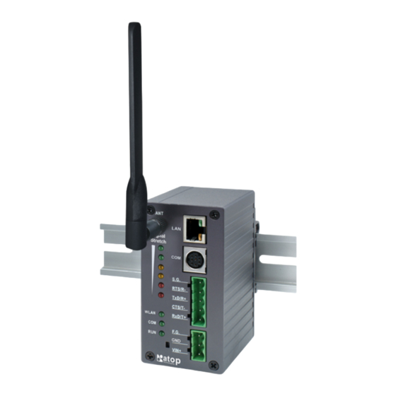
User manual Version 1.0 ABLELink SW5001 Wireless Serial Server 3. Hardware Description and settings Packaging 3.1. SW device x 1 Mini DIN to RS-232 DB 9 connector cable x 1 Wall-mounting kit x 2 Wireless Serial Server Quick Start Guide x 1 Product CD containing configuration utility and other tools Interfaces 3.2. -
Page 15: Hardware Installation Procedures
User manual Version 1.0 ABLELink SW5001 Wireless Serial Server Hardware Installation Procedures: 3.4. Prepare necessary cables, hub, power cord and RS-232/RS-485 connector. Place SW to the area that an access point can cover, or connect it via Ethernet cable with RJ45 connector. -
Page 16: Assigning New Ip Address With Arp Commands
User manual Version 1.0 ABLELink SW5001 Wireless Serial Server 3.6. Assigning new IP Address with ARP commands ARP (address resolution protocol) commands can be used to assign a static IP address on SW using its hardware MAC (media access control) address. The MAC address"0060E9-xxxxxx" is printed on the rear side of device. -
Page 17: Software Configuration
User manual Version 1.0 ABLELink SW5001 Wireless Serial Server 4. Software Configuration Configuration set by monitor.exe utility 4.1. Use monitor.exe configuration program on the product CD to check the status of SW. (see below) , One shall change SW’s IP address, gateway IP address, subnet mask, user ID (Username) and password from the utility. -
Page 18: General Infoamtion From Overview
User manual Version 1.0 ABLELink SW5001 Wireless Serial Server Fig. 13. Overview information by telnet Notes: If the SW does not receive any command within 1 minute, Telnet will be terminated automatically. The changes of networking parameters will take effect only after the SW is exit and restarted. Select “1”... - Page 19 User manual Version 1.0 ABLELink SW5001 Wireless Serial Server IP: [Allows for changes in Network Page] Gateway: [Allows for changes in Auto IP of Networking Page] Netmask: [Allows for changes in Auto IP of Networking Page] WLAN Information: MAC: [Read Only] IP: Allows for changes in Auto IP of Network Page] Gateway: [Allows for changes in Auto IP of Networking Page] Netmask: [Allows for changes in Auto IP of Networking Page]...
-
Page 20: Networking Settings
User manual Version 1.0 ABLELink SW5001 Wireless Serial Server Fig. 15. System Information from Overview (Continuous) DNS Information: DNS1: [IP address of 1 DNS Server, Allows for changes in Auto IP of Networking Page] DNS2: [IP address of 2 DNS Server, Allows for changes in Auto IP of Networking Page] DNS3: [IP address of 3 DNS Server, Allows for changes in Auto IP of Networking Page] SNMP Information:... - Page 21 User manual Version 1.0 ABLELink SW5001 Wireless Serial Server Fig. 16. Networking Settings by Telnet This screen allows for changes in IP address, subnet mask, gateway IP address and SNMP information. Please note that setting changes will not take effect until the device is restarted. Note: Press “ESC”...
- Page 22 User manual Version 1.0 ABLELink SW5001 Wireless Serial Server Configuring DNS [Main] [2 Networking] [2 DNS Settings] Fill in DNS information on the LAN Settings field. Alternatively, click on DHCP to obtain auto IP address, gateway 、 subnet mask and DNS server. Fig.
-
Page 23: Configuring Serial
User manual Version 1.0 ABLELink SW5001 Wireless Serial Server Fig. 19. SNMP Settings by Telnet 4.2.3. Configuring Serial Here one may configure COM1 parameters, include COM1 operation mode, port parameters, enabling or disabling serial buffer’s data and packet delimiter. 4.2.4. Link mode- TCP Server Mode Operation: [Main] [4 Serial Settings] [1 Link mode]... -
Page 24: Configuring Link Mode- Udp Mode
User manual Version 1.0 ABLELink SW5001 Wireless Serial Server Fig. 21. TCP Client mode in link mode 4.2.6. Configuring Link Mode- UDP mode Operation: [Main] [4 Serial Settings] [1 Link mode] [3 UDP] SW can be configured in a UDP mode to establish connection using uni-cast or broadcast data from the serial device to one or multiple host computers. -
Page 25: Configuring Packet Delimiter
User manual Version 1.0 ABLELink SW5001 Wireless Serial Server [Main] [4 Serial Settings] [2 Baud rate]/ [3 Parity]/[4 Data bits]/ [5 Stop bits]/ [6 Flow control] Here one may configure alias、baud rate、parity、data bit、stop bit and the type of flow control defined by the user, Fig. -
Page 26: Configuring Wireless Settings
User manual Version 1.0 ABLELink SW5001 Wireless Serial Server Fig. 24. Configuring UART/Network Delimiter- Timer One may choose character pattern as the packet delimiter indicated in the Figure below: Fig. 25. Configuring UART/Network Delimiter- Characters 4.2.9. Configuring Wireless Settings Operation: [Main] [3 Wireless Settings] Select “3”... -
Page 27: Site Survey
User manual Version 1.0 ABLELink SW5001 Wireless Serial Server Fig. 26. Configuring Wireless Settings by Telnet 4.2.10. Site survey Operation: [Main] [3 Wireless Setting] [5 Site Survey] Site survey function can support to auto-assignment wireless parameters, and attached to access point selected automatically. -
Page 28: Configuring Wireless Lan By Manual
User manual Version 1.0 ABLELink SW5001 Wireless Serial Server Fig. 28. Connected to AP from Site list 4.2.11. Configuring Wireless LAN by Manual The screen above display the general information of SW wireless configurations, include the access point attached , the current channel used 、 the transmitting rate at present., topology it used 、SSID defined by the user and type of authorization. -
Page 29: Configuring Ad-Hoc Mode
User manual Version 1.0 ABLELink SW5001 Wireless Serial Server 4.2.12. Configuring Ad-Hoc mode: Independent Basic Service Set (IBSS), the most basic type of IEEE 802.11 wireless LAN, is commonly referred to as an ad-hoc network. An IBSS may consists of as few as two stations. Unlike infrastructure mode, all stations are capable of communicating directly with each other without access point One may configure SW to be Ad-Hoc mode, the configuration as shown below. -
Page 30: Configuring Infrastructure Mode
User manual Version 1.0 ABLELink SW5001 Wireless Serial Server Fig. 31. Configuring WEP Settings in Ad-Hoc mode Tips. WEP Key length: Enter 5 ASCII value or 10 Hexadecimal digit if select WEP64 encryption. Enter 13 ASCII value or 26 Hexadecimal digit if select WEP128 encryption 4.2.14. -
Page 31: Configuring Share Authorization With Wep Encryption
User manual Version 1.0 ABLELink SW5001 Wireless Serial Server Fig. 32. Wireless: Open authorization and none encryption 4.2.16. Configuring share authorization with WEP encryption Topology: Infrastructure Channel: Auto-assignment from Access point Authentication: shared Encryption: WEP Fig. 33. Wireless: Share authorization and WEP encryption Note. -
Page 32: Configuring Wireless Network Via Access Point With Wpa-Psk
User manual Version 1.0 ABLELink SW5001 Wireless Serial Server 4.2.17. Configuring wireless network via access point with WPA-PSK Topology: Infrastructure Channel: Auto-assignment from Access point Authentication: WPA-PSK Encryption: TKIP or AES WPA-PSK: 8~ 63 Characters Fig. 34. Wireless: WPA-PSK authorization and TKIP encryption 4.2.18. - Page 33 User manual Version 1.0 ABLELink SW5001 Wireless Serial Server Fig. 35. Security settings by Telnet Changing Username Operation: [Main] [5 Security] [1 Change Username] Enter desired username on “New Username” fields. Fig. 36. Changing SW’s Username by Telnet Changing password Operation: [Main] [5 Security] [1 Change Password]...
-
Page 34: Configuring Using Web Browser
User manual Version 1.0 ABLELink SW5001 Wireless Serial Server 4.3. Configuring using web browser 1. Make sure the PC is on the same subnet as SW 2. Open a web browser, and then enter the same IP address as the SW. The default user name is admin and the default password is null (leave it blank). - Page 35 User manual Version 1.0 ABLELink SW5001 Wireless Serial Server Device Information SW’s system information include model name、 Device Name、 Kernel version and AP version. The information are read only and attributed from another setting page or system status (see Fig. 40). Fig.
-
Page 36: Network Setting From Network Page
User manual Version 1.0 ABLELink SW5001 Wireless Serial Server 4.3.3. Network setting from Network page There are 4 items allowed to change on Network page in which include LAN, WLAN, DNS and SNMP Information. Fig. 43. Network information by Web page 4.3.4. -
Page 37: Configuring Wlan Settings
User manual Version 1.0 ABLELink SW5001 Wireless Serial Server Fig. 45. WLAN Setting from Network web page Tip: The Network setting will be active after the device was restart. 4.3.6. Configuring DNS Settings Operation: [Network] [DNS Settings] Click on the “Network” link and the following screen shall appear. Fill in DNS information on third field. Alternatively, one may configure by checking on “Obtain an IP automatically”... -
Page 38: Wireless Configuration From Wireless Page
User manual Version 1.0 ABLELink SW5001 Wireless Serial Server Fig. 48. Wireless information by Web page There are 3 buttons can be operated 1. Rescan: Click on the “Rescan” button SW shall start site-survey procedures, then on the site-survey list will display the access point found. 2. -
Page 39: Wireless Detail Settings From Pop - Up Page
User manual Version 1.0 ABLELink SW5001 Wireless Serial Server Fig. 49. Pop-up Windows for Wireless Detail settings 4.4.1. More Cases for different wireless Applications There are some detail settings and screens for different security conductions. It is a reasonable sample if your application just was suitable about these examples. - Page 40 User manual Version 1.0 ABLELink SW5001 Wireless Serial Server Fig. 50. Open Authorization and no Encryption Attaching access point with WEP Topology: Infrastructure Channel: Auto-assignment from Access point Authentication: share Encryption: WEP WEP Key1~4: Hexadecimal or ASCII / 64 or 128bit / <WEP Key> Fig.
- Page 41 User manual Version 1.0 ABLELink SW5001 Wireless Serial Server Fig. 52. WPA-PSK Authorization and TKIP Encryption...
-
Page 42: Configuring Com Setting From Serial Page
User manual Version 1.0 ABLELink SW5001 Wireless Serial Server 4.4.2. Configuring COM Setting from Serial Page Here one may configure Serial parameters, include alias, baud rate, parity, data bit and type of flow control defined by user. COM Information by Serial Web Page 4.4.3. -
Page 43: Configuring Tcp Client Mode
User manual Version 1.0 ABLELink SW5001 Wireless Serial Server Fig. 53. TCP Server in Link mode Tip: Enable Virtual COM mode if the remote site PC’s “Serial to IP” tool installed 4.4.5. Configuring TCP Client Mode One may enter destination IP & port (default: 4660) to establish connection of counter-pair (remote) host (For example, another serial server, or PC for data-collection). -
Page 44: Configuring Serial Setting
User manual Version 1.0 ABLELink SW5001 Wireless Serial Server 4.4.7. Configuring Serial setting This filed can configure serial parameters for SW. Here one may configure Serial parameters, include UART Mode, baud rate, parity, data bit and type of flow control you wanted Configuring UART Mode: RS-232 or RS-485 or RS-422 Baud rate: 1200/2400/4800/9600/19200/38400/57600/115200 Parity: None or Odd or Even or Mark or Space... -
Page 45: Configuring System
User manual Version 1.0 ABLELink SW5001 Wireless Serial Server 4.4.9. Configuring System There are four subsystem settings for system parameters include Time, Security, Restore factory default and Restart . Fig. 57. Configuring system settings by Web 4.4.10. Configuring Time by NTP service Operation: System Time One may configure NTP Server to obtain Network time automatically or Set it manually by fill in “Set Date and Time manually”... -
Page 46: Changing Password From System Settings
User manual Version 1.0 ABLELink SW5001 Wireless Serial Server 4.4.11. Changing password from System settings Operation: System->Security Click on the “Security” link and the following screen shall appear Enter the old password on “Old Password” field; enter the new password on “New Password” and the “Verified Password”... -
Page 47: Appendix A: Using Virtual Com
User manual Version 1.0 ABLELink SW5001 Wireless Serial Server Appendix A: Using Virtual COM Virtual COM driver mode for windows converts COM data to IP data to control the RS-232C port on a SW via the IP. By creating Virtual COM ports on the PC, Virtual COM redirects the communications from the Virtual COM ports to an IP address and port number on a SW that connects the serial line device to the network. -
Page 48: Virtual Com Communication
User manual Version 1.0 ABLELink SW5001 Wireless Serial Server User can select them from a list of COM ports, which is from COM1 up to COM256. Installation Make sure you have turned off all anti-virus software before beginning the installation. Run Vcom.exe program included in the CD to install Virtual COM for your operating system. - Page 49 User manual Version 1.0 ABLELink SW5001 Wireless Serial Server Fig. 64. Login into SW by Telnet or Console 2. Select serial setting for TCP server/Client Fig. 65. Enter serial settings by Telnet 3. Enabling Virtual COM mode...
- Page 50 User manual Version 1.0 ABLELink SW5001 Wireless Serial Server Fig. 66. Enable Virtual COM mode by Telnet Running Serial/IP for program on monitoring PC On Window Start Menu, go to\program\Serial/IP for \Control panel\ select port \then select the serial port. Then the “Serial/IP for Control Panel”...
- Page 51 User manual Version 1.0 ABLELink SW5001 Wireless Serial Server by the Virtual COM Redirector, the Virtual COM Redirector must provide a username and/or password every time an application tries to access the serial server. 5. Click the Configuration Wizard button and then click the Start button that shall appear on the wizard window.
-
Page 52: Appendix B: Snmp Setup
User manual Version 1.0 ABLELink SW5001 Wireless Serial Server Appendix B: SNMP Setup B.1 SNMP Network Management Platform SW is an SNMP device that allows many popular SNMP network management platforms such as HP OpenView and SunNet Manager to conduct monitoring on the device. Depending on the network management tools used SW information can be collected from running the management tools including IP address, DNS name, system descriptions and NIC information. -
Page 53: Appendix C: Upgrading System Software
User manual Version 1.0 ABLELink SW5001 Wireless Serial Server Appendix C: Upgrading System Software Updated version of firmware can be downloaded from www.atop.com.tw. C.1 System Upgrading Procedures Follow the upgrading procedures below for the latest firmware: 1. Make sure the PC and SW on the same network. Use command “ping” or “monitor.exe” utility program to verify their availability 2. -
Page 54: Critical Issues In Upgrading Process
User manual Version 1.0 ABLELink SW5001 Wireless Serial Server Critical Issues in Upgrading Process If the upgrading is successful, SW shall re-program the flash memory, and the buzzer will beep before restarting. It takes around 5 seconds to complete the re-programming. If an error occurs during the process, SW will clear the corresponding memories, and the system will remain the same as the one before the upgrading process. -
Page 55: Appendix D: Sw's Specifications
User manual Version 1.0 ABLELink SW5001 Wireless Serial Server Appendix D: SW’s Specifications D.1 Hardware Specifications Specifications 150MHz RISC with MMU support Memory Flash: 8MB /2MB for Bootloader / SDRAM: 16MBytes. Interface Mini-PCI Slot (for Wireless Module) Watchdog Hardware Watchdog Reset Debug Port CPU Build in Com. -
Page 56: Software Specifications
User manual Version 1.0 ABLELink SW5001 Wireless Serial Server Mechanical HxWxD: 90mm x 45mm x 75mm Metal Housing for IP50 Standard Environment Operating: 0 to 60°C (32 to 140°F), 5 to 95% RH Storage: -20 to 85°C (-4 to 185°F), 5 to 95%RH D.2 Software Specifications Item Specifications... - Page 57 User manual Version 1.0 ABLELink SW5001 Wireless Serial Server Pin assignments of Mini DIN & DB9 connector is shown in the following table: RS-232 RS-485 RS-485 Pin# Full Duplex 2 wire, Half Duplex 4 wire, Full Duplex Data+ N/A (reserved) SG (Signal Ground) SG (Signal Ground) SG (Signal Ground)
-
Page 58: Beep & Led Status
User manual Version 1.0 ABLELink SW5001 Wireless Serial Server Terminal Block Connector RS-485 only uses RTS/R- and TxD/R+ for data communication while RS-232 or RS-422 uses RTS/R-, TxD/R+, CTS/T- and RxD/T+ for communicating data. Power terminal block connector Beep & LED Status Startup status “... - Page 59 User manual Version 1.0 ABLELink SW5001 Wireless Serial Server Operations Status* LED1 LED2 LED3 LED4 LED5 ★ ★ ★ ★ ★ ★ Search AP Connecting (sequentially blinking) ★ ★ ★ ★ ★ ★ Connected AP/ Get assigned IP ★ Not matched SSID ★...
-
Page 60: Run The Utility
User manual Version 1.0 ABLELink SW5001 Wireless Serial Server Configuration Utility The configuration utility is the main utility program used to display and to configure SW’s settings. D.5 Run the utility Start the program under environment and the following window shall appear. D.6 Detecting Operational Devices Follow steps below to detect all devices currently available on the network. - Page 61 User manual Version 1.0 ABLELink SW5001 Wireless Serial Server 3. Clicking on the “Configure Now” button, the target device return an ACK message indicating the modification is successful as shown follows:...
- Page 62 User manual Version 1.0 ABLELink SW5001 Wireless Serial Server The following table lists the functional descriptions for each fields. Field Name Field Descriptions Broadcast IP Except for the default IP 255.255.255.255, other items (IPs) are read from the file “seg.cfg”. This field specifies a detecting IP range. It may be a designated IP or a broadcast IP.
Need help?
Do you have a question about the ABLELink SW5001 Series and is the answer not in the manual?
Questions and answers