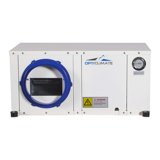
OPTICLIMATE 6000 PRO4 SPLIT Operation Instructions And Installation Manual
Hide thumbs
Also See for 6000 PRO4 SPLIT:
- Installation and user manual (24 pages) ,
- User manual (14 pages) ,
- Installation and user manual (14 pages)
Subscribe to Our Youtube Channel
Summary of Contents for OPTICLIMATE 6000 PRO4 SPLIT
- Page 1 MODELS: 6000 PRO4 SPLIT 10500 PRO4 SPLIT 15000 PRO4 SPLIT CAPACITIES: 6KW~15KW [Operation Instructions and Installation Manual]...
-
Page 2: Table Of Contents
Contents Technical Parameter Installation, Operation and Maintenance Use of Wire Controller and PCB System fault protection and code Operating Tips Maintenance Wiring diagram http://www.hicoolopticlimate.com/... -
Page 3: Technical Parameter
Technical Parameter 1.1 Specification Model ELITE 6000 SPLIT ELITE 10500 SPLIT ELITE 15000 SPLIT Cooling Capacity 10.5 Cooling Capacity 20400 34000 51400 Electrical Heater 1×1.5 2×2.0 2×2.0 Rated Input Power Cooling 2.08 3.43 5.13 Rated Input Current Cooling 15.5 Indoor Unit Power Supply 220V / 50Hz / 1P 380V / 50Hz / 3P... - Page 4 Note: Nominal cooling conditions: indoor dry bulb temperature is 27℃, indoor wet bulb temperature is 19℃, outdoor dry bulb temperature is 35℃, outdoor wet bulb temperature is 24℃. Note: 1) When the unit is shipped from the factory, the refrigerant R417A has been discharged from the unit;...
- Page 5 1.2 Dimension ELITE 6000 SPLIT ELITE 10500 SPLIT ELITE 15000 SPLIT http://www.hicoolopticlimate.com/...
-
Page 6: Installation, Operation And Maintenance
Installation, Operation and Maintenance The air-conditioner must be installed by qualified technician. Incorrect installation may lead to damage, electric shock, and fire or water leak. Before installing the air-conditioner, please read the “warning and notice” carefully to ensure the correct installation. After installation, please conduct a trial run and check whether the operation is normal or not. - Page 7 installation of the minimum air duct and pipe connection. The height of ceiling should consider the condensate water discharging height and service room. According the distance of unit’s four fastening brackets and the height of ceiling joist, make sure the location and height of four sleeves. The helix length on the sleeve can adjust the level degree of indoor unit and make sure of the unobstructed condensate water discharge.
- Page 8 2.7 Leak Check, Vacuum There is a taper mouth on the check valve of outdoor unit gas tube. It can be used to measure the pressure and charge refrigerant; As for tube leak, it must be charged to about 2.5MPa nitrogen to make sure. As for tube and indoor unit vacuum, it needs 30 minutes and the pressure lower than 30Pa.
-
Page 9: Use Of Wire Controller And Pcb
Use of Wire Controller and PCB 3.1 Wire Controller 3.2 ON/OFF □ Press <ON/OFF> to turn on the unit and the indicator light is on □ Press <ON/OFF> again, the unit will be turned off and the indicator will be off 3.3 Air conditioning operation mode selection: Press <MODE>... - Page 10 (1)When b7 is set to 0, it is the combination timing □ Set the timing stop time when the power is on □ Set the timing start time when the power is off □ After press the <SET> for 3 seconds, the hour time flashes □...
- Page 11 □ Press the <SET> again to complete the clock setting Query (can display real time) □ When the cycle timing (〖b7〗 is set to 1), press the <SET> to display the real time. □ Press <SET> to enter the query, then press <△> or <▽> to query the values of d1, d2, d4, d6, and then press <SET>...
-
Page 12: System Fault Protection And Code
Single speed fan (b4) 0(0-1) Single speed Three-speed selection Keep the original Keep the state of power on or off The controller is power off (b6) 1(0-1) state after the powered off after (working state) controller is being powered on. powered on. -
Page 13: Operating Tips
Outlet water Sensor short circuit or open After repair or temperature sensor is EE:21 circuit Stop unit replacement of the sensor damaged Inlet water Sensor short circuit or open After repair or temperature sensor is EE:22 circuit Stop unit replacement of the sensor damaged 1# high pressure switch Stop 1#... -
Page 14: Maintenance
Maintenance At the beginning of the season, make sure no obstacles exist that block the flow of inlet and outlet of air of the outdoor unit. Make sure the power supply is properly connected and power switch is in its ON position. ... - Page 15 Elite 10500Split Elite 15000Split http://www.hicoolopticlimate.com/...


Need help?
Do you have a question about the 6000 PRO4 SPLIT and is the answer not in the manual?
Questions and answers