Advertisement
Quick Links
Instruction Leaflet
Installation Instructions for Motor Operator for
Molded Case Switches
IL29C203J
E ective October 2011
Supersedes IL29C203I 9/11
Contents
Description
1-0 Introduction . . . . . . . . . . . . . . . . . . . . . . . . . .
2-0 Installation . . . . . . . . . . . . . . . . . . . . . . . . . . . .
3-0 Operation . . . . . . . . . . . . . . . . . . . . . . . . . . .
4-0 Adjustment . . . . . . . . . . . . . . . . . . . . . . . . . .
Page
. 2
2
. 6
. 9
Advertisement

Related Manuals for Eaton EOP4MT07


Summary of Contents for Eaton EOP4MT07
-
Page 1: Table Of Contents
E ective October 2011 Instruction Leaflet IL29C203J Supersedes IL29C203I 9/11 Installation Instructions for Motor Operator for L-Frame and MDL-Frame Circuit Breakers and Molded Case Switches Contents Description Page 1-0 Introduction ......2-0 Installation . -
Page 2: L-Frame And Mdl-Frame Circuit Breakers And
ALWAYS VERIFY THAT NO VOLTAGE IS PRESENT BEFORE PROCEEDING WITH THE TASK, AND ALWAYS FOLLOW GENERALLY ACCEPTED SAFE- TY PROCEDURES. EATON IS NOT LIABLE FOR THE MISAPPLICATION OF ITS PRODUCTS. The user is cautioned to observe all recommendations, warnings, and cautions relating to the safety of person- nel and equipment as well as all general and local health and safety laws, codes, and procedures. - Page 3 2-3. The breaker must be mounted with special studs (Figure 2-1 ) supplied. If the circuit breaker is already installed, replace mounting hardware. (At least one of the studs must be grounded to insure that the motor EATON CORPORATION www.eaton.com...
- Page 4 2-8 Replace the motor operator cover and screws. If dust cover sliders become separated from the operator cover, they must be installed in a proper orientation. Viewing the cover from the rear with the “PUSH-TO-TRIP ” slot on the bottom. The EATON CORPORATION www.eaton.com...
- Page 5 PAD3LD Plug-In Adaptors. 20-22 in-lb 17-19 in-lb Figure 2-2a 20-22 in-lb NOTE: If barriers become seperated from cover, orient barriers with Chamber toward Load End of Breaker. 17-19 in-lb 20-22 in-lb Figure 2-2b EATON CORPORATION www.eaton.com...
-
Page 6: Operation
3-1 ); verify that the breaker trips. Energizing the “OFF” ING THE MOTOR OPERATOR. SWITCHING OPERA- button, motor operator will “RESET” the breaker. TIONS COULD CAUSE DAMAGE TO EQUIPMENT - ESPECIALLY EQUIPMENT REQUIRING A CON- TROLLED SHUTDOWN. Figure 2-1 Motor Operator Kit EATON CORPORATION www.eaton.com... - Page 7 Installation Instructions for Motor Operator for Instruction Leaflet IL29C203J L-Frame and MDL-Frame Circuit Breakers and Molded Case Switches EATON CORPORATION www.eaton.com...
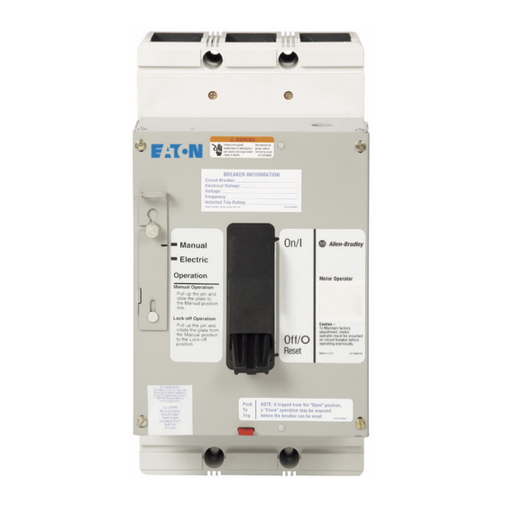
- Page 8 Installation Instructions for Motor Operator for Instruction Leaflet IL29C203J L-Frame and MDL-Frame Circuit Breakers and Molded Case Switches Figure 3-2 Motor Operator in Electrical Position Figure 3-3 Motor Operator in Manual Position EATON CORPORATION www.eaton.com...
-
Page 9: Adjustment
DAMAGE IT. ENSURE THAT THE MOTOR OPERA- 4-6. Replace the motor operator cover and cover TOR IS SECURELY MOUNTED TO A CIRCUIT screws. BREAKER BEFORE OPERATING ELECTRICALLY. 4-7. Reconnect the motor operator to the supply volt- age. EATON CORPORATION www.eaton.com... - Page 10 Motor Operating temperature; Class “A” temperature limits apply. Applied Voltage should be no less than 85% or no more than 110% of rated voltage. Operator application on supply of Vac utilizes a 480/115 Vac transformer. (Customer Supplied) EATON C ORPORATION www.eaton.com...
- Page 11 WITH ADAPTER PLATE 8.246 3.700 4.136 WITHOUT ADAPTER PLATE 5.375 14.7° 7.496 HANDLE 10.750 24.2° RESET HANDLE 1.982 9.620 1.750 .120 2.870 .870 .250 4.810 1.280 3.440 12.120 9.530 6.050 1.800 1.370 2.750 6.000 Figure 4-2 EATON C ORPORATION www.eaton.com...
- Page 12 Installation Instructions for Motor Operator for Instruction Leaflet IL29C203J L-Frame and MDL-Frame Circuit Breakers and E ective October 2011 Molded Case Switches 8.250 4.125 16.000 8.302 5.616 10.750 14.7° 7.496 HANDLE 24.2° RESET HANDLE 2.024 Figure 4-2b EATON CORPORATION www.eaton.com...
- Page 13 Installation Instructions for Motor Operator for Instruction Leaflet IL29C203J L-Frame and MDL-Frame Circuit Breakers and E ective October 2011 Molded Case Switches Notes: CORPORATION www.eaton.com EATON...
- Page 14 Installation Instructions for Motor Operator for Instruction Leaflet IL29C203J L-Frame and MDL-Frame Circuit Breakers and Molded Case Switches Notes: EATON CORPORATION www.eaton.com...
- Page 15 Installation Instructions for Motor Operator for Instruction Leaflet IL29C203J L-Frame and MDL-Frame Circuit Breakers and E ective October 2011 Molded Case Switches Notes: EATON CORPORATION www.eaton.com...
- Page 16 THE INFORMA TION, RECOMMEND ATIONS, AND DESCRIPTIONS CONT AINED HEREIN. In no event will Eaton be responsible to the purchaser or user in contract, in tort (including negligence), strict liability or other wise for any special, indirect, incidental or consequential damage or loss...
Need help?
Do you have a question about the EOP4MT07 and is the answer not in the manual?
Questions and answers