Advertisement
Quick Links
Instruction Leafl et
Installation Instructions For EG-DC Circuit Breaker
and Molded Case Switch
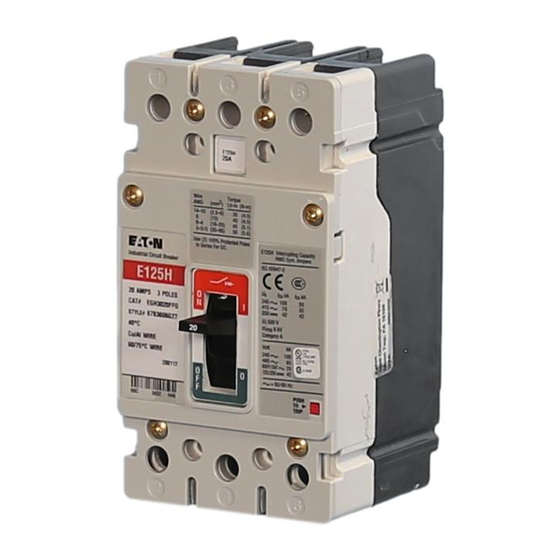
Industrial Circuit Breaker
E125H-DC
68C
3719
IL01202013EH01
E125H-DC Interrupting Capacity
Poles
In
NEMA
Series
V∂
kA
Ratings
1
125
42
2
250
50
3
500
65
Non-standard Interrupting Capacity
2 Poles In Series
300 V∂
50 kA
IEC 60947-2
Poles
In
⁄
Series
V∂
› kA
fi kA
1
125
42
42
2
250
42
42
U imp 6 kV Category A
PUSH TO TRIP
H03
Effective June 2011
Contents
Description
Introduction . . . . . . . . . . . . . . . . . . . . . . . . . . . . . . 2
Installation . . . . . . . . . . . . . . . . . . . . . . . . . . . . . . . . 3
Manual Operation . . . . . . . . . . . . . . . . . . . . . . . . . 5
Inspection and Field Testing . . . . . . . . . . . . . . . . . 6
Page
Advertisement

Related Manuals for Eaton EG-DC Series


Summary of Contents for Eaton EG-DC Series
- Page 1 Instruction Leafl et IL01202013EH01 Effective June 2011 Installation Instructions For EG-DC Circuit Breaker and Molded Case Switch Contents Description Page Introduction ......2 Installation .
- Page 2 This instruction lea et (IL) gives procedures for as all general and local health and safety laws, codes, and proce- installation and eld testing of the types EG-DC Series G dures. DC circuit breaker.
-
Page 3: Installation
Figure 4. Load Connected to Power Source. Grounded or Ungrounded Systems. Power Breaker 2 Pole Load Fig. 5-4 Figure 5. Load Isolated from Power Source. Grounded or Ungrounded Systems. If System Voltage Exceeds 125 Vdc, then Ungrounded Systems Only. E ATON CORPORATION www.eaton.com... - Page 4 Figure 6. Cover Screw Installation Positions. 2-5. If not already installed, mount terminals as shown in (Fig. Terminal Breaker Collar Figure 8. Circuit Breaker Mounting Bolt Drilling Plans and Escutcheon Dimensions. T125EF Terminal Figure 7. Terminal Installation. E ATON CORPORATION www.eaton.com...
- Page 5 PUSH-TO-TRIP Button The PUSH-TO-TRIP button checks the circuit breaker tripping func- tion and is used to periodically exercise the operating mechanism in thermal-magnetic trip units. The button is designed to be operated by a small screwdriver. E ATON CORPORATION www.eaton.com...
- Page 6 4-6. Check circuit breaker mounting hardware, tighten if necessary. 4-7 . Check area where circuit breaker is installed for any safety haz- types of chemicals can cause deterioration of electrical connections. Field Testing NEMA Standards. E ATON CORPORATION www.eaton.com...
- Page 7 Installation Instructions For EG-DC Circuit Breaker Instruction Leaflet IL01202013EH01 and Molded Case Switch E ective June 2011 Notes: E ATON CORPORATION www.eaton.com...
- Page 8 The information, recommendations, descriptions, and safety nota- tions in this document are based on Eaton’s experience and judg- al literature is published solely for information purposes and should not be considered all-inclusive. If further information is required, you should consult an authorized Eaton sales representative.
Need help?
Do you have a question about the EG-DC Series and is the answer not in the manual?
Questions and answers