Advertisement
Quick Links
Advertisement

Related Manuals for Caple WC6218


Summary of Contents for Caple WC6218
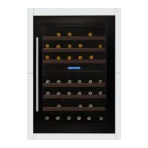
- Page 1 WC6218 Caple in-column wine cabinet Technical information Technical information...
- Page 4 WC6218 - Caple in-column wine cabinet Item Part Code Description DG2-14 Power cord DG22-476 Support bar of tank water DG13-447 water box DG1-93 Compressor PJ1-002-C Start Device / Overload Protector DG3-206 PCB board DG6-18 Transformer DG11-41 Condenser DG13-473 Limiting bar(B)
- Page 5 WC6218 - Caple in-column wine cabinet Item Part Code Description DG13-474 Support bar DG22-3005 Electrical box cover DG22-473 strengthening board DG11-45 Drier...
-
Page 7: Table Of Contents
Computer Controlled Wine Cellar JG48B Service Manual Here below we listed various faults while using the wine cellar, and the method of check-up and solve these default, and find the information of the correspondent page. Statement: (Fig.4 ) shows the reference figure Fig4 ( →6 ) shows the reference page 6 Warning: before attempting any cleaning or maintenance this unit MUST be disconnected from the electrical supply, to prevent electrical shock... -
Page 8: Safety Rules On Operation Of Repairing
1. Safety rules on operation of repairing (Rules must be obeyed). To avoid the accident during maintain the wine cooler, and make sure the product is safety, rules must be obeyed list below. Below we list the symbols and explain the danger if ignore it. ○... - Page 9 Danger ·During repairing, the power plug should be disconnected. Before remove, install, replace parts disconnect the power plug. ·Attention don’t get electric shock. When checking current, voltage or charging never touch the connectors. When changing the parts, don’t touch the charged parts within three minutes after disconnect the plug.
-
Page 10: Electrical Circuit Diagram
Notice ·Attention the hot. The running or just stop compressor and the pipe sometimes are very hot. And the heating or just stop heater is very hot. The hot will cause scald. ·Attention the hot parts of the pipe after the welding. ·Attention the refrigerant during charge and discharge it, as it will frostbite the skin when touch it. -
Page 11: Cooling System Diagram
3. Cooling system diagram. 4. Name and function on control panel. • “POWER” This LED light on means the power is on. • “ ” Use for upper compartment setting, press ‘▲’one time, the upper compartment setting temp will lower down in 1. •... -
Page 12: How To Diagnose The Fault. (E1、E2、E3、E4
before power off. According to customers’ requirement, this wine cooler can be set to that the readout display actual temp or setting temp. a. The systems enter the temperature setting mode and the setting temperature twinkling. Five seconds twinkling after stopping adjust temperature, the readout stop twinkling and the readout show actual temperature, the temperature setting mode end. - Page 13 5.2 Err code Symbol Representation Checking point Solution Check the wiring and connection Upper compartment If the connection and wiring is normal, between PCB and sensor, if it open sensor open circuit replace the sensor please. circuit. Check the wiring and connection Upper compartment If the connection and wiring is normal, between PCB and sensor, if it short...
- Page 14 5.3 Diagnose the defaults ● There isn’t any display on the display PCB. If the inner light can be turn on Check the power source (power cord, plug, socket) If the display have power input Check the PCB circuit Display PCB failed ●...
-
Page 15: Gist On Disassembly
● Not cooling (the compressor running) The compressor run for more than 30 minutes? If the door opened frequently? Don’t open the door frequently If the hot goods was put into the It can be loaded with normal temperature cabinet? wine bottle No 是... - Page 16 and lower air duct board→ Remove the back air-duct board 1. Peel off the control panel film The process: Remove all shelves →Remove control panel film Remove all shelves, then peel off the control panel film. Be careful don’t damage the control panel file, as it have to be fixing again.
- Page 17 3. Remove the middle electrical box The process: Remove the shelves→Remove the control panel film→Remove the screws →Remove the display supporter →Remove the middle electrical box Fig.3),Remove the Remove the shelves, remove the control panel and display supporter (Fig.2, four middle electrical box fixing screws, disconnect the light connecter, remove the middle electrical box.
- Page 18 Fig.5 Upper air-duct board Screws Lower air-duct board Screws 5. Remove the inner air-duct board The process: Remove the shelves→Remove the control panel film→Remove the screws →Remove the display supporter →Remove the middle electrical box→ Remove the screws→Remove the upper and lower air-duct board.→ Remove the inner air-duct board 1).After remove the upper and lower air-duct board, remove the inner air-duct board fixing screws, and then remove the inner air-duct board.
- Page 19 2).After removing the inner air-duct board, we can see suction pipe and capillary pipe joint (Fig.7) A: Capillary solder joint. B: Suction pipe solder joint C: Upper compartment fan connector D: Upper compartment sensor connector E: Heater fan connector F: Heater connector I: Lower compartment sensor G: Defrost sensor connector H: Air cycling fan connector J: evaporator...
- Page 20 the display PCB. (Fig.8& Fig.8.1) Fig.8 Fig.8.1 Display supporter Display PCB Hooks 6.1.5. How to remove the inner fan The process: Remove the shelves→Remove the control panel film→Remove the screws →Remove the display supporter →Remove the middle electrical box→ Remove the screws→Remove the upper and lower air-duct board.→...
- Page 21 →Remove the display supporter →Remove the middle electrical box→ Remove the screws→Remove the upper and lower air-duct board.→ Remove the inner air-duct board →Remove the heater fixing screws→ Remove the heater After removing the air-duct board, the heater is on the back of it, remove the fixing screws and we can remove the heater.(Fig.10)...
- Page 22 upward, and we can remove the LED light. ( Fig.12& Fig.12.1) Fig.12 Middle electrical Foam in the middle electrical LED light Fig.12.1 connector LED light Nails 2. How to remove the upper compartment LED light. The process: Remove the shelves → Remove the light cover fixing screws→ Remove the light cover→Remove the LED light fixing screws→Remove the LED light.
- Page 23 Fig.14 Fig.14.1 Screws Power box Transformer Screw Barbs Main PCB 6.2.2.How to remove the main PCB. The process of removing power box: Remove the power box → Disconnect the connectors on the main PCB → Remove the main PCB. After disconnect the connectors, press the head of the PCB supporting nails one by one and remove the main PCB at the same time.
- Page 24 Diagram of main PCB connection. ( Fig.16) Fig.16 1. Defrost sensor (T3) 2. Lower compartment sensor (T2) 3. Upper compartment sensor (T1) 4. Door switch 5. Transformer secondary Compressor 8. Transformer primary – N 7. Power - N 9. Transformer - L Power - L 11.
-
Page 25: How To Maintain The Default
Fig.17 6.2.4.How to remove the outer condenser: Process of removing the outer condenser: Remove four fixing screws → Remove the outer condenser Separate on A, H by Soldering iron for copper pipes, separate the pipe using the plier, remove four (Fig.17) screws J, remove the condenser K. - Page 26 1>. Cut off process pipe and check the refrigerant. If there is not enough refrigerant, the default of the refrigerant system should be caused by the leaking. If the refrigerant is sufficient., it is probably block in the capillary. 2>.If the default is concentrated on the cooling system, the checking procedure is as below. a.
- Page 27 2 Fan noise When the fans are running , the vanes are circumrotating rapidly and the air flows, which 1>. will cause steady and standard noise. The noise should not exceed 32dB and it is normal. (→6.1.5) If the noise is extremely high and abnormal, replace the default fan please. 2 >.
- Page 28 Aiming at the distortion of the seal with the heat dryer, and move up and down until it expand to the normal state. When it is cool, check it with the door closed, if there is any distortion, (Fig.18) dry it again until it fix for the door. 2 >.
- Page 29 Fig.20 Fig.20.1 Insulating tape 12mm(strip)*4 4 >.If above process finis, it still fault, that means the wiring damaged in the foam, you have to have another wiring along the bottom and back of the cabinet to connect the switch. Rev:A 23/23...
Need help?
Do you have a question about the WC6218 and is the answer not in the manual?
Questions and answers