Advertisement
Quick Links
Advertisement

Related Manuals for Caple WC6216


Summary of Contents for Caple WC6216
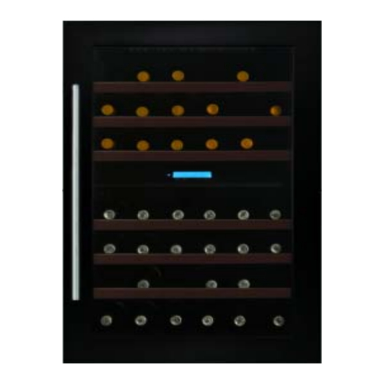
- Page 1 WC6216 Caple 60cm in-column wine cabinet Technical information...
- Page 3 WC6216 - Caple 60cm in-column wine cabinet Item Part Code Description DG2-14 Power cord DG22-476 support bar of tank water DG13-447 water box DG1-77 Compressor B40-120/B QP2-12/B DG3-206 PCB board DG6-7 Transformer DG11-41 Condenser DG26-137 Cabinet DG13-268 Decorative nail DG13-473...
- Page 4 WC6216 - Caple 60cm in-column wine cabinet Item Part Code Description DG7-33-BH DG7-41-BH PTC heater fan DG14-207 Lower hinge module DG13-475 Reed switch DG22-3014 Lid of reed switch DG13-474 support bar DG22-3005 Electrical box cove DG22-473 strengthening board DG3-13-W LED light...
- Page 6 Computer Controlled Wine Cellar WC6215 WC6216 Service Manual Here below we listed various faults while using the wine cellar, and the method of check-up and solve these default, and find the information of the correspondent page. Statement: (Fig.4 ) shows the reference figure Fig4 ( →6.1.6 ) shows the reference item 6.1.6.
- Page 7 5. How to diagnose the fault. (E1、E2、E3、E4) ——— 6 6. Gist on disassembly. ———————————————— 9 7. How to maintain the default. ———————————— 19 1. Safety rules on operation of repairing (Rules must be obeyed). To avoid the accident during maintain the wine cooler, and make sure the product is safety, rules must be obeyed list below.
- Page 8 This symbol means instance forbidden Danger ·Please make sure to discharge the rest refrigerant in the parts. ·When discharging refrigerant, make sure that it never go to the fire place and drain to outdoors. Tell the customers that they never close to the discharge place and the fire is forbidden.
- Page 9 Danger ·During repairing, the power plug should be disconnected. Before remove, install, replace parts disconnect the power plug. ·Attention don’t get electric shock. When checking current, voltage or charging never touch the connectors. When changing the parts, don’t touch the charged parts within three minutes after disconnect the plug.
- Page 10 ·Discharge the refrigerant entirely in the place without fire before disusing the refrigerant bottle. ·Don’t touch the wine cooler when the cooling pipe damaged, don’t fie inside the wine cooler, keep the windows open to exchange the air. ·Disusing the default compressor should be done outdoor without fire. ·The maximum weight of the refrigerant bottle loaded in the vehicle should be comply to stated, the bottle should be place upright, the maximum leaning angle is 40°.
-
Page 11: Electrical Circuit Diagram
Notice ·Attention the hot. The running or just stop compressor and the pipe sometimes are very hot. And the heating or just stop heater is very hot. The hot will cause scald. ·Attention the hot parts of the pipe after the welding. ·Attention the refrigerant during charge and discharge it, as it will frostbite the skin when touch it. -
Page 12: Cooling System Diagram
3. Cooling system diagram. 7/33... - Page 13 4. Name and function on control panel. • “POWER” This LED light on means the power is on. ” Use for upper compartment setting, press ‘▲’one time, the upper compartment setting temp will • “ lower down in 1. • ”...
- Page 14 a. The systems enter the temperature setting mode and the setting temperature twinkling. Five seconds twinkling after stopping adjust temperature, the readout stop twinkling and the readout show actual temperature, the temperature setting mode end. In the readout display actual temp mode, press the ‘▲’ or ‘▼’, the systems enter the temperature setting mode and the setting temperature twinkling.
- Page 15 corresponding wiring and connection, if the wiring and connection is in good condition, replace the part and check again, if it still failed, the default should be the control PCB, replace it with same model. (→ 6.2.1 ) 3 >.The self-check can be quit only disconnect the power plug. 5.2 Err code Symbol Representation...
- Page 16 minutes later, the buzzer stop, the compressor stop, the readout keep twinkling. The HI alarm can be stopped by disconnect the power plug. “LO” Low temperature warning—After turning on the wine cooler two hours, if the inner temperature is lower than 0 ºC and lasting for 15 minutes, the readout show “LO”, the buzzer alarm, and the compressor stop at the same time, when the inner temperature is over 2ºC, the LO warning stop.
- Page 17 If the inner light can be turn on Check the power source (power cord, plug, socket) Display error code? Refer to 5.2. The starter have power input? The starter failed The protector have power input? The protector failed Check the compressor Compressor fault ●...
- Page 18 The compressor run for more than 30 minutes? If the door opened frequently? Don’t open the door frequently If the hot goods was put into the It can be loaded with normal temperature cabinet? wine bottle If the door gasket airproof? Repair or replace the gasket Cooling system default ?(Check if any gas leakage or block )...
- Page 19 The process of removing the air-duct board: Remove all shelves →Remove control panel film→ Remove the display supporter→Remove the middle electrical box→Remove the upper and lower air duct board→ Remove the back air-duct board 1. Peel off the control panel film The process: Remove all shelves →Remove control panel film Remove all shelves, then peel off the control panel film.
- Page 20 Fig.3 Display Screws A connector Screws B 3. Remove the middle electrical box The process: Remove the shelves→Remove the control panel film→Remove the screws→ Remove the display supporter →Remove the middle electrical box Fig.3),Remove the Remove the shelves, remove the control panel and display supporter (Fig.2, four middle electrical box fixing screws, disconnect the light connecter, remove the middle electrical box.
- Page 21 Fig.4 Middle electrical LED light connector Screws 4. Remove the upper and lower air-duct board The process: Remove the shelves→Remove the control panel film→Remove the screws→ Remove the display supporter →Remove the middle electrical box→ Remove the screws →Remove the upper and lower air-duct board. Remove the shelves, remove the control panel and display supporter (Fig.2),Remove the four middle electrical box fixing screws, disconnect the light connecter, remove the middle electrical box.
- Page 22 Upper Fig.5 air-duct board Screws Lower air-duct board Screws 5. Remove the inner air-duct board The process: Remove the shelves→Remove the control panel film→Remove the screws→ Remove the display supporter →Remove the middle electrical box→ Remove the screws →Remove the upper and lower air-duct board.→ Remove the inner air-duct board 1)...
- Page 23 Fig.6 Inner air-duct Screws board 2).After removing the inner air-duct board, we can see suction pipe and capillary pipe joint (Fig.7) A: Capillary solder joint. B: Suction pipe solder joint C: Upper compartment fan connector D: Upper compartment sensor connector E: Heater fan connector F: Heater connector I: Lower compartment sensor G: Defrost sensor connector H: Air cycling fan connector...
- Page 24 Fig.7 6.1.3.How to remove the evaporator The process: Remove the shelves→Remove the control panel film→Remove the screws→ Remove the display supporter →Remove the middle electrical box→ Remove the screws →Remove the upper and lower air-duct board.→ Remove the inner air-duct board →...
- Page 25 6.1.4. How to remove the display PCB The process: remove the display supporter→ remove the display PCB After removing the display supporter, from the back of the supporter pull the hooks, and remove the display PCB. (Fig.8& Fig.8.1) Fig.8 Fig.8.1 Display supporter Display PCB...
- Page 26 Front of the inner air-duct Screws board front Fan 1 Screws Fig.9 Screws Fan 3 Fan 2 6.1.6. How to remove the heater The process: Remove the shelves→Remove the control panel film→Remove the screws→ Remove the display supporter →Remove the middle electrical box→ Remove the screws →Remove the upper and lower air-duct board.→...
- Page 27 The process: Remove the shelves→Remove the control panel film→Remove the screws→ Remove the display supporter →Remove the middle electrical box→Remove the upper air-duct board →remove the sensor cover →remove the sensor 1. Remove the upper air-duct board(A), pull out the two expanding nails(D), the sensor cover(C) loose, pull out the sensor (B).
- Page 28 Middle Fig.12 electrical Foam in the middle electrical LED light Fig.12.1 connector LED light Nails 2. How to remove the upper compartment LED light. The process: Remove the shelves → Remove the light cover fixing screws→ Remove the light cover→Remove the LED light fixing screws→Remove the LED light. ①, Remove the shelves.
- Page 29 6.2.1. How to remove the transformer. The process of removing power box: Remove the screws fixing power box → remove the power box → Remove the transformer. ①.Remove four power box fixing screws. ( Fig.14) ②.Remove the power box. ( Fig.14.1) ③.Remove the two transformer fixing screws.
- Page 30 Four barbs fixing PCB Main PCB Fig.15 Diagram of main PCB connection. ( Fig.16) 25/33...
-
Page 31: How To Remove The Compressor
Fig.16 1. Defrost sensor (T3) 2. Lower compartment sensor (T2) 3. Upper compartment sensor (T1) 4. Door switch 5. Transformer secondary Compressor 7. Power - N 8. Transformer primary – N 9. Transformer - L Power - L 11. PTC heater 12. - Page 32 H: condenser and filter joint I: Outer water tank support J:Four condenser fixing screws K: Condenser Fig.17 6.2.4.How to remove the outer condenser: Process of removing the outer condenser: Remove four fixing screws → Remove the outer condenser Separate on A, H by Soldering iron for copper pipes, separate the pipe using the plier, remove four (Fig.17) screws J, remove the condenser K.
-
Page 33: Check The Cooling System
empty unit (assuming ambient temp of 32 degrees centigrade and continuous operation). If not, check the compressor, cooling fans, controller, and sensors. If all these are working normally, there is probably a cooling pipe fault. 7.1. Check the compressor If the wine cooler not cooling, check the current with the Amp meter,refer to rating label, if it too high or too low, cut the discharge pipe (Fig. -
Page 34: Noise Problem
( →6.1.2 ) c. If all the soldering point in b is not leaking, there are two possibility, one is leakage in the inner condenser (or anti- dew pipe), another is the damage on the spare parts in the cooling system. - Page 35 noise is steady and not exceeds 42 dB, it’s normal. If noise is not steady or very high, it’s (→6.2.3) compressor fault and it should be maintained or replaced. If compressor’s shock absorption rubber is hardening or damaged, or fixing screw of 2>.
- Page 36 (→7.6) 1>. Refer to 2>. If the capillary touch the inner cabinet and the air duct panel, adjust the position of the capillary and add the incabloc plastic. 7.8.Oil jammed noise Fault: intermittent and deep jet noise coming from inside of the capillary. Cause: Compressor oil flowing into the cooling system pipe work probably due to the capillary slightly out of alignment during transportation (→...
- Page 37 7.10. Unstable temperatures inside the cabinet. The unstable temperature is caused by the evaporator fans cease, and it can be check by the below method: When the compressor is running, the light “Run” is on, the fan should be running, if the fan stop, check the whether is any fault in the fan or fan connection.
- Page 38 Insulating tape 12mm(strip)*4 4 >.If above process finis, it still fault, that means the wiring damaged in the foam, you have to have another wiring along the bottom and back of the cabinet to connect the switch. Rev:A 33/33...
Need help?
Do you have a question about the WC6216 and is the answer not in the manual?
Questions and answers