Advertisement
Quick Links
Advertisement

Related Manuals for Caple WC6115


Summary of Contents for Caple WC6115
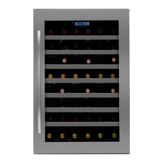
- Page 1 WC6115 Caple 60cm In-column Wine Cabinet Technical information...
- Page 2 New product information sheet WC6115 Product name: Caple 60cm In-column Wine Cabinet Description: WC6115 Product code: Features Width 590mm Height 885mm Single temperature zone for red or white wine No frost compressor cooling system Fan circulated cool air for even temperature distribution...
- Page 5 WC6115 - Caple 60cm In-column Wine Cabinet Item Part Code Description Quantity DG2-14 Power cord DG22-476 support bar of Water tank DG13-447 Water tank DG1-77 Compressor B40-120/B QP2-12/B DG3-205 PCB board DG6-7 Transformer DG11-41 Condenser DG26-136 Cabinet DG13-268 Decorative nail...
- Page 6 WC6115 - Caple 60cm In-column Wine Cabinet Item Part Code Description Quantity DG14-176 Lower hinge DG22-3004 reed switch DG22-3040 lid of reed switch DG13-474 Support bar DG22-3005 Electrical box cover DG22-473 strengthening bracket...
- Page 8 Computer Controlled Wine Cellar WC6115 Service Manual Here below we listed various faults while using the wine cellar, and the method of check-up and solve these default, and find the information of the correspondent page. Statement: (Fig.4 ) shows the reference figure Fig4 ( →6.1.6 ) shows the reference item 6.1.6.
- Page 9 4. Name and function on control panel. ———————— 5 5. How to diagnose the fault. (E1、E2、E3、E4) ——— 6 6. Gist on disassembly. ———————————————— 8 7. How to maintain the default. ———————————— 13 1. Safety rules on operation of repairing (Rules must be obeyed). To avoid the accident during maintain the wine cooler, and make sure the product is safety, rules must be obeyed list below.
- Page 10 Danger ·Please make sure to discharge the rest refrigerant in the parts. ·When discharging refrigerant, make sure that it never go to the fire place and drain to outdoors. Tell the customers that they never close to the discharge place and the fire is forbidden.
- Page 11 Danger ·During repairing, the power plug should be disconnected. Before remove, install, replace parts disconnect the power plug. ·Attention don’t get electric shock. When checking current, voltage or charging never touch the connectors. When changing the parts, don’t touch the charged parts within three minutes after disconnect the plug.
- Page 12 When measuring the grounding resistance make sure that the test range is more than 1MΩ. Make sure the power cord and plug never be pinched on rear of the wine cooler. Exchange the power cord when it damaged. Clean the flake of the plug when it dirty. Notice ·Attention the hot.
- Page 13 2. Electrical circuit diagram. 3. Cooling system diagram. 6/24...
- Page 14 4. Name and function on control panel. • “ ” Press ‘▲’,the setting temp will raise up in 1. • • “ ” Press ‘▼’,the setting temp will lower down in 1. • “ ”Press one time, the light on, press again, the light off, it is not effect by the door switch. Press it and hold •...
- Page 15 temperature, the readout stop twinkling and the readout show actual temperature, the temperature setting mode end. b. In the readout display setting temp mode, press the ‘▲’ or ‘▼’, the systems enter the temperature setting mode and the setting temperature twinkling. Five seconds twinkling after stopping adjust temperature, the readout stop twinkling and the readout show setting temperature, the temperature setting mode end.
- Page 16 Symbol Representation Checking point Solution If the connection and wiring is Inner sensor open Check the wiring and connection between PCB and normal, replace the sensor circuit. sensor, if it open circuit. please. Inner sensor short Check the wiring and connection between PCB and If the connection and wiring is circuit.
- Page 17 If the inner light can be turn on Check the power source (power cord, plug, socket) Display error code? Refer to 5.2. The starter have power input? The starter failed The protector have power input? The protector failed Check the compressor Compressor fault ●...
- Page 18 Gist on disassembling the inner cabinet. 6.1.1. How to remove the shelves. Push the shelf to the end, and revolve the shelf on either side, make the stopper on the out of the guiding rail, then pull the shelf out (Fig.1). Shelves Fig.1 6.1.2.
- Page 19 Air-duct board Screws Screws Inner air-duct board Fig.2 Fig.2.1 2>.Remove the screws fixing inner air-duct board, disconnect the connecter of the fan, and remove the inner air-duct board, we can see the welding points around the evaporator. (Fig.3 ) A: Capillary joint B: Evaporator joint C: Evaporator D: Inner sensor connector...
- Page 20 The process of removing the evaporator: remove all shelves→ remove the air-duct board → remove the inner air-duct board→ separate the evaporator from the compressor and dry filter on the joints. (Fig.3 )Heat the joint E,G (Fig.12 ) You can see the evaporator is joint to suction pipe and capillary. in the compressor room, and disconnect the pipe from compressor by using the plier.
- Page 21 Fixing nails Sensor cover Air-duct board Fig.5 6.1.6.How to remove the electrical box The process of removing the electrical box: Remove all shelves → loose the fixing screws → disconnect the connectors → remove the controlled box loose the fixing screws and the box loose, disconnect the connectors, Remove the shelves (Fig.1);...
- Page 22 Slotted Fig.6 Fig.7 screwdriver Electrical Screws Electrical front LED light Screws cover 6.1.8.How to remove the LED light The process of removing the LED light: Remove all shelves → loose the fixing screws → disconnect the connectors → remove the controlled box → remove the LED light. Remove the electrical box, then remove the screws fixing LED light, remove the LED light.
- Page 23 Fig.8 Fig.8.1 Screws Electrical box Transformer Screws Barb Main PCB 6.2.2.How to remove the main PCB. The process of removing the power PCB: Remove the electrical box → disconnect the connectors → remove the power PCB. Disconnect all connectors, then press the barbs one by one pull the PCB upward, remove the power PCB.(Notice: It is better to press the barbs by using the cuspate plier ).
-
Page 24: How To Remove The Compressor
Fig.11 1. Defrost sensor (red) 2. Inner sensor (white) 3. Door switch (Yellow) 4. Compressor 5. Power - N 6. Transformer primary - N 7. Transformer secondary 8. Transformer primary - L 9. Power L 10. Display 11. Inner fan (yellow) 12. - Page 25 Fig.12 6.2.3.How to remove the outer condenser: Process of removing the outer condenser: Remove four fixing screws → Remove the outer condenser evaporator Separate on A, H by Soldering iron for copper pipes, separate the pipe using the plier, remove four screws (Fig.12) J, remove the condenser K.
-
Page 26: Check The Cooling System
feel the discharge pipe, if the obvious air pressure from compressor, if the current still very high or very low or the discharge pipe with small air pressure, the compressor fault, replace the compressor please. Notice. After cut the discharge pipe and process pipe, in case of suck the damp, the compressor should ne power on long time (no exceed 15 minutes is best). -
Page 27: Noise Problem
1>. Using the vacuum pump form a vacuum in the system, via the joints of the high/low-pressure pipe, the (Fig.12 showing B), high-pressure low-pressure pipeline is on the process pipe of the compressor pipeline is on the process pipe of the filter. Apply the vacuum pump for approximately 20 minutes. Until the vacuum is lower than 100Pa. - Page 28 7.6. Refrigerant jet noise Default: There is continuous noise like a water spray from the capillary. Reason: The end of the capillary is in the wrong position, or there are rough edges on the end of the capillary Solution: (→6.1.3) (Fig.3)...
- Page 29 Replace the door seal or close the door well. If the door seal is slightly not air-proof, it can be 1 >. repaired by the heat dryer. Aiming at the distortion of the seal with the heat dryer, and move up and down until it expand to the normal state.
- Page 30 2 >.If the readout show E1, E2, E3, E4, it is the inner sensor open or short circuit default(5.2) (Fig.2.1), (Fig.14,Fig.14.1) check the circuit and repair it or replace the sensor. 3 >.Remove the screws, loose the clamp(Fig.14); (Fig.14.1) 4 >. Cut the sensor, the rest wiring should be long enough to reconnect. Sensor fixing Fig.14 Fig.14.1...
- Page 31 Fig.16 Fig.16.1 Scissors Screws Fig.17 Fig.17.1 Insulating tape 12mm(strip)*4 4 >.If above process finis, it still fault, that means the wiring damaged in the foam, you have to have another wiring along the bottom and back of the cabinet to connect the switch. Rev: A 24/24...
Need help?
Do you have a question about the WC6115 and is the answer not in the manual?
Questions and answers