
Related Manuals for Rockwell Automation ANORAD LZ Series


Summary of Contents for Rockwell Automation ANORAD LZ Series
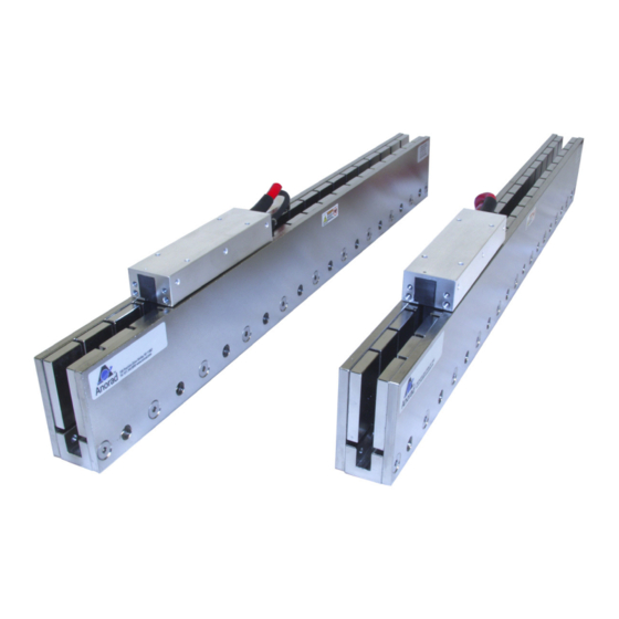
- Page 1 ANORAD LZ Series Linear Motors ANUAL Publication LZ-UM001A-EN-P January 2008...
- Page 2 In no event will Rockwell Automation, Inc. be responsible or liable for indirect or consequential damages resulting from the use or application of this equipment. The examples and diagrams in this manual are included solely for illustrative purposes.
-
Page 3: Table Of Contents
Table of Contents Preface About This Publication ........5 Who Should Use This Manual. - Page 4 Appendix A Introduction ..........31 Specifications and Dimensions Trapezoidal Hall Effect Circuit .
-
Page 5: About This Publication
Preface Read this preface to familiarize yourself with the manual. This manual provides detailed installation instructions for mounting, wiring, About This Publication maintaining, and troubleshooting your LZ Linear Motor. This manual is intended for engineers or technicians directly involved in the Who Should Use This installation, wiring, and maintenance of this LZ linear motor. - Page 6 Publication LZ-UM001A-EN-P - January 2008...
-
Page 7: Chapter 1 Introduction
Chapter Understanding and Caring for Your Linear Motor The LZ Linear Motor Series description and maintenance is given in this Introduction section. Product features are explored and the part numbering system is explained. This information will help you develop an understanding of the linear motor’s basic configuration. -
Page 8: Motor Features
(digital) Hall effect feedback module may be attached to the front of the motor coil. The LZ linear motor may also be commutated via software. Anorad and Rockwell Automation offers a full line of compatible servo controls and drives. Motor Features •... -
Page 9: Identifying Your Linear Motor Components
Understanding and Caring for Your Linear Motor Use the following key to identify your linear stage and its options coil and Identifying Your Linear magnet assemblies. Motor Components LZ - xxx - x - xxx - x - x - x - xx - x Cable Length 0 = 300 mm, 1 = 600 mm,... -
Page 10: Maintenance
Understanding and Caring for Your Linear Motor Anorad linear motors require no maintenance when operated in a relatively Maintenance clean environment. For operation in harsh and dirty environments, minimal cleaning is recommended every 6 months. Clean the metallic debris and other contaminants from the air gap. To effectively remove the metal debris use a strip of masking tape. -
Page 11: Chapter 2 Introduction
Chapter Installation Use the following section to guide you through installation and start-up of Introduction your LZ linear motor. Topic Page Unpacking and Inspection Installing the Linear Motor Motor Power and Feedback Cable Signal Names Motor-Hall Phasing and Sequence Positive Motor Direction Motor Coil Thermal Protection Operational Guidelines Inspect motor assemblies for damage that may have occurred in shipment. -
Page 12: Installing The Linear Motor
Installation Use the following procedures to install the magnet channel and the motor coil Installing the Linear Motor to create a linear motor. Mount the Magnet Channel The required tools are: • magnet channel alignment tool (supplied). • aluminum straight edge. •... - Page 13 Installation 3. Verify that the mounting configuration for the magnet channel and coil fits in envelope dimensions shown in diagram. Mounting Configuration A Mounting Configuration B Mounting Configuration C 0.10 (.003) 0.83 ± 0.40 (0.033 ± 0.015) Catalog Number mm (in.) LZM-030- 80.0 (3.15) LZM-050-...
-
Page 14: Motor Coil Mounting Hardware Requirements
Installation 4. Install the first magnet channel using M6 SHCS for mounting configuration A, or M5 SHCS for mounting configuration B and C. Non-magnetic tools and hardware such as beryllium copper, 300 series stainless steel, and others should be used. If not available, proceed carefully since magnetic and ferrous items will be attracted to the magnet channel. -
Page 15: Mount The Motor Coil
Installation Mount the Motor Coil Follow these procedures to mount the motor coil to your machine slide. 1. Be sure the motor coil mounting face is clean and free of burrs. 2. Position the slide at the end of travel where the cable is to exit. 3. - Page 16 Installation Disconnect the input power supply before installing or servicing ATTENTION the motor. The motor lead connections can short and cause damage or injury if not well secured and insulated. Insulate the connections, equal to or better than the insulation on the supply conductors.
-
Page 17: Motor-Hall Phasing And Sequence
Installation The LZ linear motor family is compatible with off-the-shelf brushless motor Motor-Hall Phasing and servo drives. The servo drive will see them as a two-pole motor with a full Sequence electrical cycle of 60 millimeters (360 degrees equivalent rotary motion). The brushless motor drives and controls must have two control functions for suitable commutation of a linear motor. -
Page 18: Positive Motor Direction
Installation Motor Phasing Diagram Back EMF Voltage vs. Hall Signals Back Voltage Digital Hall Signals 0° 60° 120° 180° 240° 300° 360° Linear Travel mm (in.) 60 (2.36) Phasing direction = the coil toward motor power cable for moving coil configuration as shown in Positive Motor Direction or the magnet assembly away from power cable for moving magnet configuration. -
Page 19: Motor Coil Thermal Protection
Installation Motor Coil Thermal Protection LZ linear motors with the thermal protection option will supply ATTENTION a signal that indicates the motor temperature limit condition. This signal should be used by the motor control or drive system to immediately shut down the motor power on an open condition. -
Page 20: Operational Guidelines
Installation After installing the motor and before powering up your system for the first Operational Guidelines time, performed the Motor Coil Electrical Test on page 23 to verify motor condition. Moving parts can injure. Before running the motor, make sure ATTENTION all components are secure and the magnet mounting hardware is below magnet surface. -
Page 21: Chapter 3 Introduction
Chapter Troubleshooting Use this section to diagnose the health of motor coil and the Hall effect Introduction module. Topic Page Hall Effect Module PTC Thermal Signal Motor Coil Electrical Test Motor Back EMF Tests Checking the Magnet Channel Butting Polarity Use the following procedures to troubleshoot the Hall effect module. -
Page 22: Hall To Back Emf Phasing
Troubleshooting 6. Check for the proper logic levels (approximately 0V = low, +V = high) and the sequence: S1 leads S2 leads S3 with approximately 120 electrical degree spacing in between. Connect the probe common to the Hall signal common. Hall to Back EMF Phasing 1. -
Page 23: Motor Coil Electrical Test
Troubleshooting Perform this test after installation and when a coil electrical fault is suspected. Motor Coil Electrical Test Dangerous voltages, forces and energy levels exist in servo ATTENTION controlled systems. Extreme care must be exercised when operating, maintaining or servicing the linear motor to prevent harm to personnel or equipment 1. -
Page 24: Motor Back Emf Tests
Troubleshooting 7. Compare the phase resistance readings to the cold resistance specification of the specific coil model. The three reading should be about the same and comparable to the cold resistance specified for your model. When the coil is hot the resistance reading should still be balanced and but may be as mush as 30 …... -
Page 25: Check Measured Back Emf To Specification
Troubleshooting 5. Repeat step 4 comparing V-W to U-W. In this case U-W should lead V-W by 60 . The shapes and peak voltages should be approximately the same. Note that probe common = W. Be sure to use the same phasing direction as in step 4. -
Page 26: Checking The Magnet Channel Butting Polarity
Troubleshooting Mechanical displacement of one electrical cycle = motor magnetic pitch (180 in inches multiplied by two. Note that the published specification may already be in “cycles.” In this case do not multiply by two. Use the following equation to calculate back EMF constant: mechanical displacement of one cycle (in) ---- - ------------------------------------------------------------------------------------------------------... - Page 27 Troubleshooting 5. Using an oscilloscope, connect one channel between any Hall signal (output) and the Hall signal common. 6. Slowly and steadily move the motor by hand in one direction over the whole travel. Monitor the waveshape as you are doing this. The Hall signal should alternate between a high and low DC level of equal duty cycle (squarewave), as the Hall module passes over the alternating polarity magnets.
- Page 28 Troubleshooting Publication LZ-UM001A-EN-P - January 2008...
-
Page 29: Chapter 4 Introduction
Chapter Hall Effect Module Removal and Replacement Use this section to change the Hall effect module. Introduction Topic Page Hall Effect Module If a problem is detected with a Hall effect module use the following Hall Effect Module procedures to remove and replace the unit. The following procedures require a 3 mm hex key, non-magnetic preferred, and cardboard to fit in magnet channel. - Page 30 Hall Effect Module Removal and Replacement 2. Place the module at the end of the motor with the sensor blade inserted in the magnet channel. 3. Install the two M4 SHCS using a 3 mm hex key. Do not over tighten. 4.
-
Page 31: Introduction
Appendix Specifications and Dimensions Anorad/Rockwell Automation publication listed in Additional Resources on Introduction page 5 may supersede the information in this appendix. Topic Page Trapezoidal Hall Effect Circuit Positive Temperature Coefficient (PTC) Thermistor Environmental Specifications for LZ Linear Motors LZ Series Linear Motor Dimensions... -
Page 32: Trapezoidal Hall Effect Circuit
Specifications and Dimensions Trapezoidal Hall Effect Circuit Description Specifications Input Power 5…24V dc, 20 mA max. Output NPN, open collector, 10 mA max. • Trapezoidal Hall Signals, 120 Hall signal common Spacing, Open Collector Transistor (24V max.) Outputs (Pull-up Resistor External) •... -
Page 33: Lz Series Linear Motor Dimensions
Specifications and Dimensions Linear motors are designed to metric dimensions. Inch dimensions are LZ Series Linear Motor conversions from millimeters. Untolereated dimensions are for reference. Dimensions LZ Series Linear Motor Coil (Catalog Number LZ-030-0-xxx-x-0-x-x-x) Dimension are in mm (in.) 80.00 28.00 Thermistor Wires (3.15) - Page 34 Specifications and Dimensions LZ Linear Motor Magnet Channel (Catalog Number LZM-030-0-xxx) L ±0.25 (±0.010) 25.00 Setup Dimension Y ±0.05 (±0.002) (0.984) 14.0 9.50 Ø (10.0) (0.55) 56.1 (0.374) 55.0 (0.39) (2.21) (2.17) See Tabluation 17.5 60.00 Ø THRU Ø 4.00 +0.06 60.00 Air gap will result from setting the plates to (0.69)
- Page 35 Specifications and Dimensions LZ Series Linear Motor Coil (Catalog Number LZ-030-T-xxx-x-0-x-x-x) Dimension are in mm (in.) 80.00 28.00 Thermistor Wires (3.15) 0.25mm (24) GA (1.10) 35.00 26.00 (1.02) (1.38) Power Cable Ø6.1 mm (0.24), 0.75 mm (18 GA) Mounting Holes M4 X 0.7 X 8.5 mm Deep 4.50 (Flying Leads) Quantity A1 - See table...
- Page 36 Specifications and Dimensions Magnet Channel Layout (Catalog Number LZM-030-T-xxx) L ±0.25 (±0.010) 25.00 Setup Dimensions Y ±0.05 (±0.002) (0.984) 14.0 Ø (10.0) (0.55) (0.37) 56.0 55.0 (0.39) (2.21) (2.17) See Tabulation 17.5 Ø 4.00 +0.06 60.00 Ø THRU 60.00 Air gap will result from setting the plates to (0.69) (2.362) (0.23)
- Page 37 Specifications and Dimensions LZ Series Linear Motor Coil (Catalog Number LZ-030-HT-xxx-x-0-x-x-x) Dimension are in mm (in.) 80.00 28.00 Thermistor Wires 0.25mm (24) GA (3.15) (1.10) 26.00 35.00 (1.02) (1.38) Power Cable Ø6.1 mm (0.24), 0.75 mm (18 GA) Mounting Holes M4 X 0.7 X 8.5 mm Deep 4.50 (Flying Leads) Quantity A1 - See table...
- Page 38 Specifications and Dimensions Magnet Channel Layout Drawing (Catalog Number LZM-030-HT-xxx) L ±0.25 (±0.010) Y ±0.05 (±0.002) 25.00 Setup Dimension (0.984) 14.0 Ø (10.0) (0.55) (0.37) 56.0 55.0 (0.39) (2.21) (2.17) See Tabulation 17.5 Ø 4.00 +0.06 60.00 Ø THRU Air gap will result from setting the 60.00 (0.70) (2.362)
- Page 39 Specifications and Dimensions LZ Series Linear Motor Coil (Catalog Number LZ-050-0-xxx-x-0-x-x-x) Dimension are in mm (in.) 80.00 28.00 Thermistor Wires (3.15) (1.10) 0.25 mm 24 GA 35.00 26.00 (1.38) (1.02) Power Cable Ø 6.1 mm (0.24), 0.75 mm (18 GA) Mounting Holes M4 X 0.7 X 8.5 mm Deep 4.50 (Flying Leads)
- Page 40 Specifications and Dimensions Magnet Channel Layout (Catalog Number LZM-050-0-xxx) L ±0.25 (±0.010) 25.00 Setup Dimension Y ±0.05 (±0.002) 0.984 Ø(10.00) 14.0 76.0 75.00 (0.37) (0.394) (0.55) (2.99) (2.95) See Tabulation Ø 5.75 THRU 60.00 4.00 +0.06 17.5 60.00 Ø (2.362) (0.226) Air gap will result from setting the plate to 37.8...
- Page 41 Specifications and Dimensions LZ Series Linear Motor Coil (Catalog Number LZ-050-T-xxx-x-0-x-x-x) Dimension are in mm (in.) 80.00 28.00 Thermistor Wires (3.15) (1.10) 0.25 mm (24) GA 35.00 26.00 (1.38) (1.02) Power Cable Ø 6.1 mm (0.24), 0.75 mm (18 GA) Mounting Holes M4 X 0.7 X 8.5 mm Deep 4.50 (Fliying Leads)
- Page 42 Specifications and Dimensions Magnet Channel Layout (Catalog Number LZM-050-T-xxx) L ±0.25 (±0.010) 25.00 Setup Dimension Y ±0.05 (±0.002) 0.984 9.50 Ø(10.00) 76.00 14.0 75.00 (0.374) (0.394) (0.55) (2.992) (2.953) See Tabulation 60.00 Ø 5.75 THRU 4.00 +0.06 60.00 17.50 Ø (0.226) (2.362) Air gap will result from setting the plate to...
- Page 43 Specifications and Dimensions LZ Series Linear Motor Coil (Catalog Number LZ-050-HT-xxx-x-0-x-x-x) Dimension are in mm (in.) 80.00 28.00 Thermistor Wires (3.15) (1.10) 0.25 mm (24) GA 35.00 26.00 (1.38) (1.02) Power Cable Ø 6.1 mm (0.24), 0.75 mm (18 GA) Mounting Holes M4 X 0.7 X 8.5 mm Deep 4.50 (Fliying Leads)
- Page 44 Specifications and Dimensions Magnet Channel Layout (Catalog Number LZM-050-HT-xxx) L ±0.25 (±0.010) 25.00 Setup Dimension Y ±0.05 (±0.002) 0.984 Ø(10.0) 76.0 14.0 75.0 (0.37) (0.39) (0.55) (2.99) (2.95) See Tabulation 60.00 Ø 5.75 THRU 4.00 +0.06 17.5 60.00 Ø (0.226) (2.362) Air gap will result from setting the plate to (0.69)
- Page 45 Specifications and Dimensions LZ Series Linear Motor Coil (Catalog Number LZ-075-0-xxx-x-0-x-x-x) Dimension are in mm (in.) Thermistor Wires 80.0 28.0 (3.15) 0.25 mm (24) GA (1.10) 26.0 35.0 (1.02) Power Cable Mounting Holes M4 X 0.7 X 8.5 mm Deep Ø6.1 mm (0.24), 0.75 mm (18 GA) Quantity A1 - See table...
- Page 46 Specifications and Dimensions Magnet Channel Layout Drawing (Catalog Number LZM-075-0-xxx) L ±0.25 (±0.010) 25.00 Setup Dimension Y ±0.05 (±0.002) (0.984) 106.0 100.0 (4.17) 19.0 Ø (10.0) (3.94) (0.37) (0.75) (0.39) See Tabulation 4.00 +0.06 17.5 60.00 Ø THRU 60.00 Ø Air gap will result from setting the plates to (0.69) (0.23)
- Page 47 Specifications and Dimensions LZ Series Linear Motor Coil (Catalog Number LZ-075-T-xxx-x-0-x-x-x) Dimension are in mm (in.) Thermistor Wires 80.0 28.0 0.25 mm (24) GA (3.15) (1.10) 26.00 35.00 (1.02) Power Cable Mounting Holes M4 X 0.7 X 8.5 mm Deep Ø...
- Page 48 Specifications and Dimensions Magnet Channel Layout (Catalog Number LZM-075-T-xxx) L ±0.25 (±.010) 25.00 Setup Dimension Y ±0.05 (±.002) (0.984) 106.0 100.0 (4.17) 19.0 Ø(10.0) (3.94) (0.75) (0.37) (0.39) See Tabulation 4.00 +0.06 17.5 Ø THRU 60.00 60.00 Ø Air gap will result from setting the plate to (0.69) (0.23) 43.7...
- Page 49 Specifications and Dimensions LZ Series Linear Motor Coil (Catalog Number LZ-075-HT-xxx-x-0-x-x-x) Dimension are in mm (in.) Thermistor Wires 80.0 28.0 0.25 mm (24) GA (3.15) (1.10) 26.00 35.00 (1.02) Power Cable Mounting Holes M4 X 0.7 X 8.5 mm Deep Ø...
- Page 50 Specifications and Dimensions Magnet Channel Layout (Catalog Number LZM-075-HT-xxx) L ±0.25 (±0.010) Setup Dimension 25.00 Y ±0.05 (±0.002) (0.984) 106.0 100.0 (4.17) 19.0 Ø (10.0) (3.94) (0.75) (0.37) (0.39) See Tabulation 4.00 +0.06 17.5 60.00 Ø THRU 60.00 Ø Air gap will result from setting the plates to (0.69) (2.362) (0.23)
- Page 51 Specifications and Dimensions LZ Series Linear Motor Coil (Catalog Number LZ-100-0-xxx-x-0-x-x-x) Dimension are in mm (in.) Thermistor Wires 80.00 28.00 0.25 mm (24 GA) (3.15) 26.00 35.00 (1.02) (1.38) POWER CABLE Ø 6.1 mm (0.24), 0.75 mm (18 GA) Mounting Holes M4 X 0.7 X 8.5 mm Deep (Flying Leads) Quantity A1 - See table 4.50...
- Page 52 Specifications and Dimensions Magnet Channel Layout (Catalog Number LZM-100-0-xxx) L ±0.25 (±0.010) 25.00 Setup Dimension Y±0.05 (±0.002) (0.984) 131.0 (5.16) 125.0 (4.92) 19.0 Ø(10.0) (0.75) (0.37) (0.39) See Tabulation Ø4.00 +0.06 17.5 60.00 Ø THRU 60.00 Air gap will result from setting the plate to (0.69) (2.362) (0.23)
- Page 53 Specifications and Dimensions LZ Series Linear Motor Coil (Catalog Number LZ-100-T-xxx-x-0-x-x-x) Dimension are in mm (in.) Thermistor Wires 80.00 28.00 0.25mm (24) GA (3.15) (1.10) 35.00 26.00 (1.38) (1.02) Power Cable Ø 6.1 mm (0.24), 0.75 mm (18 GA) Mounting Holes M4 X 0.7 X 8.5 mm Deep (Flying Leads) 4.50 Quantity A1 - See Table...
- Page 54 Specifications and Dimensions Magnet Channel Layout (Catalog Number LZM-100-T-xxx) L ±0.25 (±0.010) 25.00 Setup Dimension Y ±0.05 (±0.002) (0.984) 131.0 (5.16) 125.00 (4.92) 19.0 Ø(10.0) (0.75) (0.37) (0.39) See Tabulation Ø4.00 +0.06 17.5 60.00 Air gap will result from setting the plates to Ø...
- Page 55 Specifications and Dimensions LZ Series Linear Motor Coil (Catalog Number LZ-100-HT-xxx-x-0-x-x-x) Dimension are in mm (in.) Thermistor Wires 80.00 28.00 0.25mm (24) GA (3.15) (1.10) 35.00 26.00 (1.38) (1.02) Power Cable Ø 6.1 mm (0.24), 0.75 mm (18 GA) Mounting Holes M4 X 0.7 X 8.5 mm Deep (Flying Leads) 4.50 Quantity A1 - See Table...
- Page 56 Specifications and Dimensions Magnet Channel Layout (Catalog Number LZM-100-HT-xxx) L ±0.25 (±.010) 25.00 Setup Dimension Y ±0.05 (±.002) (0.984) 131.0 (5.16) 125.00 (4.92) 19.0 Ø 10.0 (0.75) (0.37) (0.39) See Tabulation Ø4.00 +0.06 17.5 60.00 Ø THRU 60.00 Air gap will result from setting the plates to (0.69) (2.362) 51.3...
-
Page 57: Introduction
Appendix Mounting Bolts and Torque Values This appendix provides typical torque values for standard and metric bolts. Introduction Recommended Seating Torque for Metric Bolts Pitch Plain Cadmium Plated Zinc Bolt Size (metric) Nm (in-lb) Nm (in-lb) Nm (in-lb) M1.6 0.35 0.29 (2.6) 0.22 (1.95) 0.41(3.64) - Page 58 Mounting Bolts and Torque Values Recommended Seating Torque for Mild Steel Rb 87 or Cast Iron Rb 83 (1), (2) Bolt Size Plain Cadmium Plated Plain Cadmium Plated Nm (in-lb) Nm (in-lb) Nm (in-lb) Nm (in-lb) – – 0.24 (2.1) 0.18 (1.6) 0.44 (3.89) 0.53 (4.7)
- Page 59 Mounting Bolts and Torque Values Recommended Seating Torque for Brass Rb 72 (1), (2) Bolt Size Plain Cadmium Plated Plain Cadmium Plated Nm (in-lb) Nm (in-lb) Nm (in-lb) Nm (in-lb) – – 0.24 (2.1) 0.18 (1.6) 0.43(3.8) 0.33 (2.9) 0.46 (4.1) 0.34 (3.0) 0.71 (6.3) 0.53 (4.7)
- Page 60 Mounting Bolts and Torque Values Recommended Seating Torque for Aluminum Rb 72 (2024-T (1), (2) Bolt Size Plain Cadmium Plated Plain Cadmium Plated Nm (in-lb) Nm (in-lb) Nm (in-lb) Nm (in-lb) 0.24 (2.1) 0.18 (1.6) 0.34 3.0v 0.44 (3.8) 0.33 (2.9) 0.46 (4.1) 0.71 (6.3) 0.53 (4.7)
- Page 61 Index LZ-050-T-xxx-x-0-x-x-x LZ-075-0-xxx-x-0-x-x-x abrasives LZ-075-HT-xxx-x-0-x-x-x accelerations LZ-075-T-xxx-x-0-x-x-x acetone LZ-100-0-xxx-x-0-x-x-x 15, 20, 26 air gap LZ-100-HT-xxx-x-0-x-x-x alignment tool LZ-100-T-xxx-x-0-x-x-x aluminum straight edge magnet channel attraction LZM-030-HT-xxx magnetic LZM-030-T-xxx automatic implantable cardioverter LZM-050-0-xxx LZM-050-HT-xxx defibrillator (AICD) LZM-050-T-xxx LZM-075-0-xxx LZM-075-HT-xxx 17, 18, 21, 26 back EMF LZM-075-T-xxx LZM-100-0-xxx...
- Page 62 Index Hall neutral access 8, 17 12, 14 effect module non-magnetic removal tools replacement normal operating temperature feedback troubleshooting hardware requirements open collector transistor magnet channel operational guidelines optimal commutation inspection installation motor phases motor coil phasing direction sequence power cable logic levels procedure cleaning...
- Page 63 Index temperature limit unpacking 9, 19 thermal protection thermistor cable through hole warning automatic implantable cardioverter tools defibrillator (AICD) trapezoidal commutation powerful forces troubleshooting winding code Hall effect module wire colors PTC thermal signal witness marks Publication LZ-UM001A-EN-P - January 2008...
- Page 64 Europe/Middle East/Africa: Rockwell Automation, Vorstlaan/Boulevard du Souverain 36, 1170 Brussels, Belgium, Tel: (32) 2 663 0600, Fax: (32) 2 663 0640 Asia Pacific: Rockwell Automation, Level 14, Core F, Cyberport 3, Cyberport Road, Hong Kong, Tel: (852) 2887 4788, Fax: (852) 2508 1846 Publication LZ-UM001A-EN-P - January 2008 ©...
Need help?
Do you have a question about the ANORAD LZ Series and is the answer not in the manual?
Questions and answers