
Related Manuals for Rockwell Automation MPL-B640


Summary of Contents for Rockwell Automation MPL-B640
-
Page 1: Table Of Contents
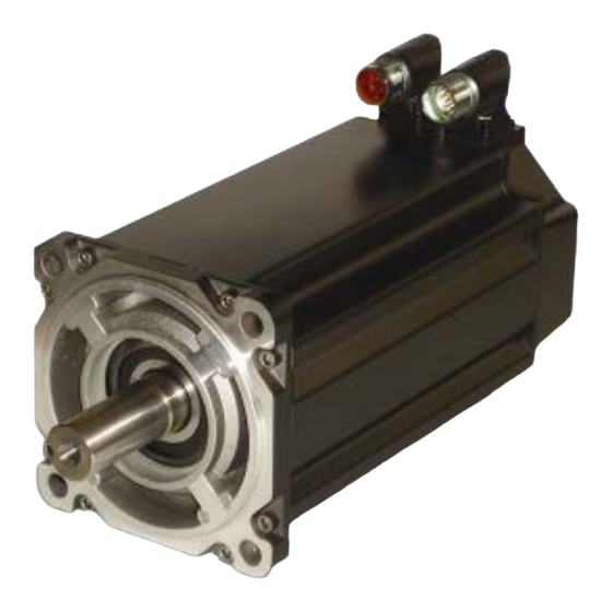
Installation Instructions MP-Series Low Inertia Servo Motor with 215 mm or Larger Frame Size Catalog Numbers MPL-B640, MPL-B660, MPL-B680, MPL-B860, MPL-B880, MPL-B960, MPL-B980 Topic Page Important User Information Catalog Number Explanation Before You Begin Install the Motor Verify Connector O-ring and Backshell Seal... -
Page 2: Important User Information
In no event will Rockwell Automation, Inc. be responsible or liable for indirect or consequential damages resulting from the use or application of this equipment. -
Page 3: Catalog Number Explanation
MP-Series Low Inertia Servo Motor Installation Instructions Catalog Number Explanation MP L - B 6 80 F - M J 7 2 A A FACTORY DESIGNATED OPTIONS = Standard = ATEX Protection Rating of Group II, Zone 2 MOUNTING FLANGE = IEC Metric BRAKE = No Brake... -
Page 4: Before You Begin
MP-Series Low Inertia Servo Motor Installation Instructions About the MP-Series Low Inertia Motors MP-Series low-inertia motors feature single-turn or multi-turn high resolution encoders, and are available with 24V DC brakes. These compact brushless servo motors combine the characteristics of the MP-Series low-inertia motors with unique features designed for food and beverage applications. - Page 5 MP-Series Low Inertia Servo Motor Installation Instructions • The brake option on this servo motor is a spring-set holding brake that releases when voltage is applied to the brake coil. A separate power source is required to disengage the brake. This power source can be applied by a servo motor controller or manual operator control.
- Page 6 MP-Series Low Inertia Servo Motor Installation Instructions Using Couplings and Pulleys Mechanical connections to the motor shaft, such as couplings and pulleys, require a torsionally rigid coupling or a reinforced timing belt. The high dynamic performance of servo motors can cause couplings, pulleys, or belts to loosen or slip over time.
- Page 7 MP-Series Low Inertia Servo Motor Installation Instructions Preventing Electrical Noise ElectroMagnetic Interference (EMI), commonly called electrical noise, can reduce motor performance. Effective techniques to counter EMI include filtering the AC power, use of shielded cables, separating signal cables from power wiring, and practicing good grounding techniques.
-
Page 8: Install The Motor
MP-Series Low Inertia Servo Motor Installation Instructions Install the Motor All motors include a mounting pilot for aligning the motor on the machine. Preferred fasteners are hardened steel. The installation must comply with all local regulations and use equipment and installation practices that promote safety and electromagnetic compatibility. -
Page 9: Change Connector Orientation
MP-Series Low Inertia Servo Motor Installation Instructions Change Connector Orientation You may rotate the connector housings up to 180 degrees. • The M23 feedback connector and the M40 power/brake connector are fully rotatable as installed. • The M58 power/brake connector, on MPL-B8xx and MPL-B9xx motors with higher current requirements, must be physically removed and repositioned in 90°... - Page 10 MP-Series Low Inertia Servo Motor Installation Instructions Rotating the M58 Power/Brake Circular DIN Connector Follow these steps to rotate a M58 power/brake DIN connector. 1. Remove the four 10-32 x 5/8 locking screws from the connector housing. 2. Rotate the connector housing 90 or 180 degrees. If binding of the wire bundles prevents rotation of the connector, you can gain access to the internal motor wiring as described in the following steps.
- Page 11 MP-Series Low Inertia Servo Motor Installation Instructions Build and Route Cables Knowledgeable cable routing and careful cable construction improves system performance. Install cables as described in these guidelines. • Keep wire lengths as short as physically possible. Do not tightly gather or coil the excess length of a power cable. Heat is WARNING generated within a cable whenever power is applied.
- Page 12 MP-Series Low Inertia Servo Motor Installation Instructions Ground Shielded Signal Wires within a Power Cable Always connect the shield on any signal wire pair routed inside a power cable to the overall machine ground. If any shield on a power cable is not grounded, high voltage can be present on that shield. ATTENTION Make sure there is a connection to ground for all shield wires inside a power cable, and for the overall power cable shield.
-
Page 13: Mount The Motor
MP-Series Low Inertia Servo Motor Installation Instructions Mount the Motor Follow these steps to mount the motor on a machine. 1. Provide sufficient clearance, heatsink mass, and air flow for the motor so it stays within the operating temperature range of 0…40 °C (32…104 °F). Do not enclose the motor unless cooling air is forced across the motor, and keep other heat producing devices away from the motor. - Page 14 MP-Series Low Inertia Servo Motor Installation Instructions Attach Motor Cables Follow these steps to attach the feedback and power/brake cables after the motor is mounted. Make sure that cables are installed and restrained to prevent uneven tension or flexing at ATTENTION the motor-to-cable connections.
- Page 15 MP-Series Low Inertia Servo Motor Installation Instructions 3. Carefully align the flat surface on the feedback or the power/brake cable plug (shown in the diagram) with the flat surface on the motor connector. The motor orientation shown is used to clearly show the alignment marker on IMPORTANT each cable socket.
-
Page 16: Connector Data
MP-Series Low Inertia Servo Motor Installation Instructions Connector Data These tables identify the pinouts for the feedback, and the power with brake connectors. M23 Feedback Connector M40 or M58 Power with Brake Connector MPL-B6xx, MPL-B8xx, and MPL-B6xx, MPL-B8xx, and MPL-B9xx MPL-B9xx Sin+ Phase U... -
Page 17: Product Dimensions
MP-Series Low Inertia Servo Motor Installation Instructions Product Dimensions The dimensions in the table are for non-brake motors with a single-turn or multi-turn encoder. Footnotes provide tolerances for the common dimensions, and the additional dimensions for the brake motors. Publication MP-IN002C-EN-P - April 2009... - Page 18 MP-Series Low Inertia Servo Motor Installation Instructions (7), (8) Motor L-LB Series MPL-B (in.) (in.) (in.) (in.) (in.) (in.) (in.) (in.) (in.) 93.8 154.0 38.002 10.0 5.20 246.5 303.8 80.0 17.8 (3.69) (6.06) (1.4961) (0.3937) (0.205) (9.70) (11.96) (3.150) (0.70) 354.6 (13.96) 405.4...
- Page 19 MP-Series Low Inertia Servo Motor Installation Instructions Shaft End Threaded Hole (in.) (in.) (in.) mm (in.) (in.) (in.) (in.) (in.) (in.) 223.8 183.6 112.5 215.0 180.0 184.9 14.50 3.73 M12 x 1.75- 6H (8.81) (7.23) (3.15) (8.465) (7.0867) (7.28) (0.579) (0.147) thread depth 28 (1.10)
-
Page 20: Motor Load Force Ratings
500 rpm 1000 rpm 1500 rpm 2000 rpm 3000 rpm Motor kg (lb) kg (lb) kg (lb) kg (lb) kg (lb) MPL-B640 253 (557) 200 (442) — 159 (351) 139 (307) MPL-B660 275 (607) 219 (482) — 173 (382) 151 (334) - Page 21 500 rpm 1000 rpm 1500 rpm 2000 rpm 3000 rpm Motor kg (lb) kg (lb) kg (lb) kg (lb) kg (lb) MPL-B640 89 (197) 66 (146) — 48 (107) 41 (90) MPL-B660 98 (217) 72 (159) — 54 (118) 45 (99)
-
Page 22: Accessory Kits
They provide environmental sealing up to and including an IP66 rating and proper shield termination. For a complete listing of available cables refer to your drive manual, contact your nearest Rockwell Automation sales office, or access the information from the references in Additional Resources. - Page 23 MP-Series Low Inertia Servo Motor Installation Instructions Shaft Key Shaft keys are constructed of steel. The specified tolerance provides an interference fit (slightly larger than the opening) for a secure and rigid connection. Damage can occur to the motor bearings and the feedback device if sharp impacts ATTENTION applied to the shaft during installation of couplings and pulleys, or a shaft key.
-
Page 24: Specifications
MP-Series Low Inertia Servo Motor Installation Instructions Specifications MP-Series Low Inertia Servo Motors Attribute Value Temperature, operating 0…40 °C (32…104 °F) Temperature, storage -30…70 °C (-22…158 °F) Relative humidity, storage 5…95% noncondensing Atmosphere, storage noncorrosive IP Rating Motor with a shaft seal IP66 - dust tight, powerful water jets Motor without a shaft seal, and mounted in this direction: •... -
Page 25: Additional Resources
Specifications, motor/servo-drive system combinations, publication GMC-SG001 and accessories for Kinetix motion control products. You can view or download publications at http://literature.rockwellautomation.com. To order paper copies of technical documentation, contact your local Rockwell Automation distributor or sales representative. Publication MP-IN002C-EN-P - April 2009... - Page 26 MP-Series Low Inertia Servo Motor Installation Instructions Notes: Publication MP-IN002C-EN-P - April 2009...
- Page 27 MP-Series Low Inertia Servo Motor Installation Instructions Notes: Publication MP-IN002C-EN-P - April 2009...
- Page 28 New Product Satisfaction Return Rockwell Automation tests all of its products to ensure that they are fully operational when shipped from the manufacturing facility. However, if your product is not functioning and needs to be returned, follow these procedures.
Need help?
Do you have a question about the MPL-B640 and is the answer not in the manual?
Questions and answers