Table of Contents
Advertisement
Quick Links
TRANSLATION OF THE ORIGINAL INSTRUCTIONS
We advise you to read this manual carefully, which contains all the instructions for
maintaining the appliance's aesthetic and functional qualities.
For further information on the product: www.smeg.com
Contents
4
4
8
8
9
9
9
10
11
11
12
12
13
14
15
15
16
17
18
20
24
24
27
27
27
28
29
31
33
35
35
40
42
3
Advertisement
Table of Contents

Related Manuals for Smeg CS6CMXA


Summary of Contents for Smeg CS6CMXA
-
Page 1: Table Of Contents
5.2 Electrical connection 5.3 Instructions for the installer TRANSLATION OF THE ORIGINAL INSTRUCTIONS We advise you to read this manual carefully, which contains all the instructions for maintaining the appliance’s aesthetic and functional qualities. For further information on the product: www.smeg.com... -
Page 2: 7Instructions
Instructions 1 7Instructions • Keep children under the age of 8 away from the appliance when it 1.1 General safety instructions is in use. • Cleaning and maintenance must Risk of personal injury not be carried out by • During use the appliance unsupervised children. - Page 3 Instructions • Fats and oils can catch fire if they • The items inside the storage overheat. Do not leave the compartment could be very hot appliance unattended while after using the oven. preparing foods containing oils or • DO NOT USE OR STORE fats.
- Page 4 Instructions • Do not try to repair the appliance • Racks and trays should be inserted yourself or without the intervention as far as they will go into the side of a qualified technician. guides. The mechanical safety locks that prevent them from being •...
- Page 5 Instructions • Do not use the open door to rest • Do not use abrasive or corrosive pans or trays on the internal glass detergents (e.g. scouring pane. powders, stain removers and metallic sponges) on glass parts. • Cooking vessels or griddle plates should be placed inside the •...
-
Page 6: Manufacturer's Liability
Instructions • The appliance must be connected For this appliance to earth in compliance with • Ensure that the appliance is electrical system safety standards. switched off before replacing the • Use cables withstanding a bulb. temperature of at least 90 °C. •... -
Page 7: Identification Plate
Instructions 1.4 Identification plate To dispose of the appliance: • Cut the power supply cable and The identification plate bears the remove it along with the plug. technical data, serial number and brand name of the appliance. Do not Power voltage remove the identification plate for Danger of electrocution any reason. -
Page 8: How To Read The User Manual
Instructions 1.7 How to read the user manual This user manual uses the following reading conventions: Instructions General information on this user manual, on safety and final disposal. Description Description of the appliance and its accessories. Information on the use of the appliance and its accessories, cooking advice. -
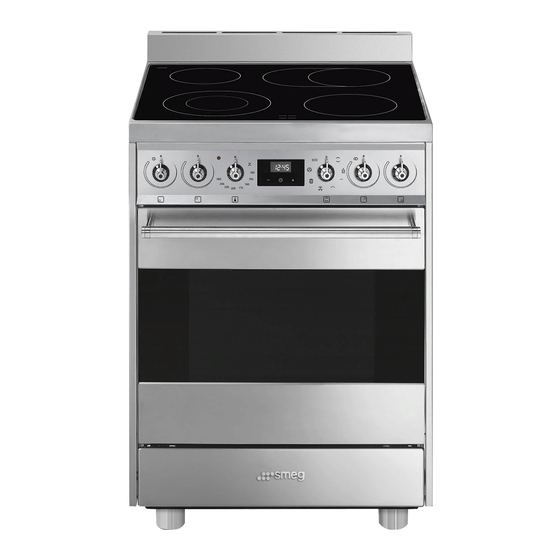
Page 9: Description
Description 2 Description 2.1 General Description 1 Backguard 5 Seal 2 Hob 6 Door 3 Control panel 7 Storage compartment 4 Oven light 8 Fan Rack/tray support frames... -
Page 10: Hob
Description 2.2 Hob External Max. power Internal Max. power Zone diameter (mm) draw (W)* diameter (mm) draw (W)* 1200 1800 2200 oval plate 2200 1100 * power levels are approximate and may vary according to the settings made and the mains voltage. -
Page 11: Other Parts
Description 3 Temperature knob Cooling fan This knob allows you to select the cooking temperature. Turn the knob clockwise to the required value, between the minimum and maximum setting. 4 Programmer clock Useful for displaying the current time, setting programmed cooking operations and programming the minute minder timer. -
Page 12: Available Accessories
Description 2.5 Available accessories Deep tray Rack Useful for collecting fat from foods placed on the rack above and for cooking pies, Useful for supporting containers with food pizzas and baked desserts. during cooking. Some models are not provided Tray rack with all accessories. -
Page 13: Use
3 Use High temperature inside the storage compartment 3.1 Instructions Danger of fire or explosion High temperature inside the oven • Do not spray any spray products near during use the appliance. Danger of burns • Do not use or leave flammable materials near the appliance or the storage •... -
Page 14: Using The Accessories
First use Improper use 1. Remove any protective film from the Risk of damage to surfaces outside or inside of the appliance, including accessories. • Do not cover the bottom of the oven 2. Remove any labels (apart from the cavity with aluminium or tin foil sheets. -
Page 15: Using The Hob
Racks and trays 3.3 Using the hob Racks and trays have to be inserted into the Residual heat side guides until they come to a complete stop. Improper use • The mechanical safety locks that prevent Danger of burns the rack from being removed accidentally must face downwards and •... -
Page 16: Using The Oven
Switching off the cooking zones • When preparing dishes with long cooking times, you can save time and To switch off the cooking zones, turn the energy by using a pressure cooker, corresponding knobs to which helps to retain vitamins contained in the food. - Page 17 Functions list Grill The heat coming from the grill Static element gives perfect grilling results As the heat comes from above and above all for thin and medium below at the same time, this system thickness meat and, in combination is particularly suitable for certain with the rotisserie (where fitted), types of food.
-
Page 18: Programmer Clock
Fan with circulaire Vapor Clean The combination of the fan and the This function makes cleaning easier circulaire heating element using the steam produced by a little (incorporated in the rear of the oven) quantity of water poured onto the allows you to cook different foods appropriate groove placed on the on several levels, as long as they... - Page 19 Timed cooking Setting the time Timed cooking is the function If the time is not set, the oven will which allows a cooking operation not switch on. to be started and then ended after a specific length of time set by the On the first use, or after a power failure, the user.
- Page 20 7. Press the clock key to reset the 4. Use the key to set the required minutes. (for example 1 hour) programmer clock. 5. Press the menu key . The text It is not possible to set a cooking time of more than 10 hours. will appear on the display in sequence with the pre-set cooking To cancel the set programming...
- Page 21 10. Return the function and temperature Minute minder timer knobs to 0. The minute minder timer does not 11. To turn off the buzzer just press any key stop the cooking operation but of the programmer clock. rather informs the user when the set time has run out.
-
Page 22: Using The Storage Compartment
Modifying the set data 3.6 Using the storage compartment There is a storage compartment at the 1. Press the clock key bottom of the appliance. To open it, pull the handle towards you. It can be used to store 2. Use the value increase and value cookware or metallic objects necessary decrease... - Page 23 Advice for cooking with the Grill Advice for defrosting and proving • Meat can be grilled even when it is put • Place frozen foods without their into the cold oven or into the preheated packaging in a lidless container on the oven if you wish to change the effect of first shelf of the oven.
- Page 24 Cooking information table Weight Temperature Time Food Function Shelf (Kg) (°C) (minutes) Lasagne 3 - 4 Static 220 - 230 45 - 50 Pasta bake 3 - 4 Static 220 - 230 45 - 50 Veal roast Turbo/Circulaire 180 - 190 90 - 100 Pork loin Turbo/Circulaire...
-
Page 25: Cleaning And Maintenance
Cleaning and maintenance 4 Cleaning and maintenance 4.2 Cleaning the surfaces To keep the surfaces in good condition, 4.1 Instructions they should be cleaned regularly after use. Let them cool first. Improper use Risk of damage to surfaces Ordinary daily cleaning Always and only use specific products that •... -
Page 26: Cleaning The Hob
Cleaning and maintenance 4.3 Cleaning the hob Weekly cleaning Clean and maintain the hob once a week Cleaning the glass ceramic hob using an ordinary glass ceramic cleaning Light coloured marks from pans with product. Always follow the manufacturer’s aluminium bases can be easily cleaned off instructions. -
Page 27: Cleaning The Door
Cleaning and maintenance 4.4 Cleaning the door 3. To reassemble the door, put the hinges in the relevant slots in the oven, making sure Removing the door that grooved sections A are resting For easier cleaning it is recommended to completely in the slots. - Page 28 Cleaning and maintenance Removing the internal glass panes 4. Clean the external glass pane and the panes removed previously. Use For easier cleaning the internal glass panes absorbent kitchen roll. In case of of the door can be removed. stubborn dirt, wash with a damp sponge 1.
-
Page 29: Cleaning The Oven Cavity
Cleaning and maintenance 4.5 Cleaning the oven cavity Cleaning the racks and trays In order to keep your oven in the best Clean the racks and trays with warm water possible condition, clean it regularly after and non-abrasive detergents. Carefully letting it cool down. - Page 30 Cleaning and maintenance Vapor Clean • Spray a water and washing up liquid solution inside the oven using a spray Vapor Clean is an assisted nozzle. Direct the spray towards the side cleaning procedure which walls, upwards, downwards and facilitates the removal of dirt. towards the deflector.
-
Page 31: Extraordinary Maintenance
Cleaning and maintenance End of the Vapor Clean cycle 4.6 Extraordinary maintenance 4. Open the door and wipe away the less Installing and removing the seal stubborn dirt with a microfibre cloth. To remove the seal: 5. Use a non-scratch sponge with brass •... - Page 32 Cleaning and maintenance Replacing the internal light bulb 4. Slide out and remove the light bulb. Live parts Danger of electrocution • Unplug the appliance. • Use protective gloves. 1. Completely remove all accessories from inside the oven. 2. Remove the rack/tray support frames. Do not touch the halogen light 3.
-
Page 33: Installation
Installation 5 Installation Any wall units installed above the appliance’s worktop must be positioned at 5.1 Positioning least Y mm from it. If a hood is installed above the hob, refer to the hood instruction Heavy appliance manual to ensure the correct clearance is Crushing hazard left. - Page 34 Installation Appliance overall dimensions 600 mm 600 mm B - Class 2 subclass 1 min. 150 mm (Built-in appliance) 900 - 915 mm 750 mm 450 mm 600 mm Minimum distance from side walls or other flammable material. Minimum cabinet width (=A). C - Class 2 subclass 1 (Built-in appliance) The appliance must be installed by a...
- Page 35 Installation Appliance dimensions: location of Assembling the upstand electrical connection (mm) The upstand provided is an integral part of the product; it must be fastened to the appliance prior to installation. The upstand must always be positioned and secured correctly on the appliance. 1.
- Page 36 Installation Positioning and levelling Fastening to the wall Heavy appliance The anti-tip devices must be installed in order to prevent the Risk of damage to the appliance appliance from tipping over. • Insert the front legs first and then the rear 1.
- Page 37 Installation 3. Assemble the fastening bracket. 5. Align the base of the fastening bracket with the ground and tighten the screws to fix the measurements. 6. Use 50 mm for the distance from the side of the appliance to the bracket holes. 4.
-
Page 38: Electrical Connection
Installation 7. Move the bracket onto the wall and 5.2 Electrical connection mark the position of the holes to be Power voltage drilled in the wall. Danger of electrocution • Have the electrical connection performed by authorised technical personnel. • Use personal protective equipment. •... - Page 39 Installation The appliance can work in the following The aforementioned power cables modes: are sized taking into account the • 220-240 V 2~ coincidence factor (in compliance with standard EN 60335-2-6). Access to the terminal board To connect the power supply cable, you 3 x 4 mm²...
-
Page 40: Instructions For The Installer
Installation 3. Proceed with installation of the power Fixed connection supply cable. Fit the power line with an all-pole disconnection switch, with a clearance between its contacts that allows the complete disconnection as per the overvoltage category III, in compliance with the installation regulations.
Need help?
Do you have a question about the CS6CMXA and is the answer not in the manual?
Questions and answers