These instructions apply only for the destination countries listed on the appliance’s data plate. 
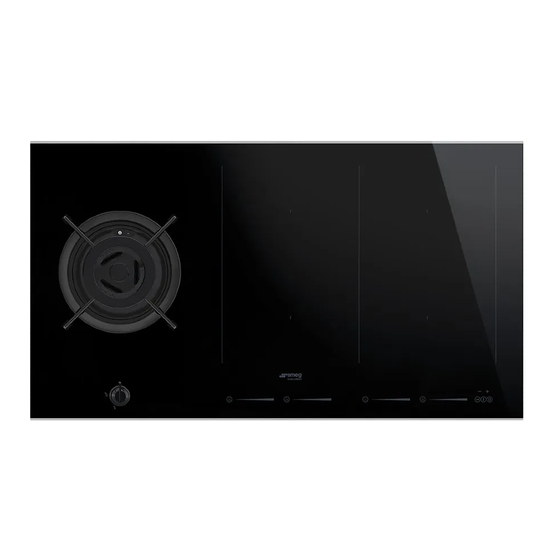
This is a class 3 built-in hob. We advise you to read this manual carefully, which contains all the instructions for maintaining the appliance’s aesthetic and functional qualities. For further information on the product: www.smeg.com...
Instructions 1 Instructions • Keep children under eight years of age at a safe distance if they are 1.1 General safety instructions not constantly supervised. • Do not allow children younger Risk of personal injury than 8 years old to come near the •...
Page 3
Instructions • The cooking process must always • Do not pull the cable to remove be monitored. Short cooking the plug. processes must be monitored • If the power supply cable is continuously. damaged, contact technical • When in use, do not place metal support immediately and they will objects, such as dishes or cutlery, replace it.
Page 4
Instructions • Do not spray any spray products Installation near the oven. • THIS APPLIANCE MUST NOT BE • Do not use plastic kitchenware or INSTALLED IN BOATS OR containers when cooking food. CARAVANS. • The cooking vessels or griddle •...
Page 5
Instructions • The gas connection should be • The tightening torque of the screws carried out by authorised persons. of the terminal supply wires must be 1.5 - 2 Nm. • Installation with flexible hose must be carried out so that the length of •...
Instructions • The glass ceramic surface is highly 1.2 Appliance purpose resistant to impact. However, • This appliance is intended for prevent hard, solid objects falling cooking food in the home onto the cooking surface as they environment. Every other use is may cause it to break if they are considered improper.
Instructions 1.5 Identification plate • Deliver the appliance to the appropriate recycling centre for The identification plate bears the electrical and electronic technical data, serial number and equipment waste, or return it to the brand name of the appliance. Do not retailer when purchasing an remove the identification plate for equivalent product, on a one for...
Instructions 1.7 How to read the user manual This user manual uses the following reading conventions: Instructions General information on this user manual, on safety and final disposal. Description Description of the appliance and its accessories. Information on the use of the appliance and its accessories, cooking advice.
Description 2 Description 2.1 General Description 65 cm AUX = Auxiliary F = Front plate controls R = Rapid R = Rear plate controls C = General controls zone...
Page 10
Description 75 cm AUX = Auxiliary F = Front plate controls UR = Ultra rapid R = Rear plate controls C = General controls zone...
Page 11
Description 90 cm UR* = Ultra rapid SX = Left induction cooking zone DX = Right induction cooking zone F = Front plate controls R = Rear plate controls C = General controls zone...
Description 2.2 Symbols Gas cooking zone Induction cooking zone On/Off key: turns the hob on or off. Rear cooking zone Pause key: pauses cooking. Front cooking zone Controls lock key: prevents accidental operation of controls. Burner knobs Increase key: increases the cooking time or timer.
Description Advantages of induction cooking 2.3 Available accessories The appliance is equipped with an WOK ring induction generator for each cooking zone. Each generator located under the glass ceramic cooking surface creates an electromagnetic field which induces a thermal current in the base of the pan.
3 Use Improper use Risk of damage to surfaces 3.1 Instructions Improper use • Do not use aluminium foil to cover the Danger of burns burners or hob body. • Cooking vessels or griddle plates • Make sure that the flame-spreader should be placed inside the perimeter of crowns are correctly positioned in their the hob.
Malfunctions High temperature Any of the following indicate a malfunction Danger of fire or explosion and you should contact a service centre. • Damage to kitchen utensils. • Do not use or leave flammable materials • The burners do not ignite properly. near the appliance or directly •...
3.4 Using the gas burners Correct positioning of the flame- spreader crowns and burner caps All the appliance’s control and monitoring devices are located together Before lighting the hob burners, make sure on the front panel. The burner controlled that the flame-spreader crowns are by each knob is shown next to the knob.
Page 17
Correct positioning of the grids Ring reducers Under the grids there are silicone rests with The ring reducers must be rested on the hob a hole that must be centred onto the grid. Make sure they are properly matching fixing pins on the surface. positioned.
3.5 Using the induction hot plates To see whether the pan is suitable, bring a magnet close to the bottom: if it is attracted, On first connection to the electrical the pan is suitable for induction cooking. mains, an automatic check will be If you do not have a magnet, you can put a carried out that will switch on all small amount of water in the pan, place it...
Page 19
Limiting the cooking duration Power levels The hob has an automatic device which The power in the cooking zone can be limits the duration of use. adjusted to various levels. The table shows the levels suitable for various types of If the cooking zone settings are not cooking.
Page 20
Switching on the cooking zone 2. Move your finger to the left or right on the automatically scroll bar to select the cooking power, After switching on the hob: between , or else activate • Position a pan (suitable for induction cooking and not empty) on the cooking the Power function (see “...
Page 21
The display of the cooking zone used will Quick selection turn on: the power value indicated is This function allows you to quickly set the cooking zones to the 2. Move your finger all the way to the right required power. of the scroll bar to select the Power function.
Page 22
The same parameters are set on both Multizone function cooking zones. This function can be used to: It is only possible to activate the operate two Multizone function between cooking zones (front and rear) cooking zones that are vertically simultaneously connected (F and R).
Page 23
If using a large, oval or oblong pan, ensure Cooking guidelines that you position this at the centre of the The table below shows the power values cooking zone. which can be set, together with the corresponding type of food. Settings may vary depending on the amount of food and consumer taste.
Page 24
Residual heat Keep Warm Function Improper use The Keep warm function allows Danger of burns you to keep cooked food hot. • Supervise children carefully as they To activate the Keep Warm function, first cannot easily see the residual heat turn on the hob, then: indicator.
Page 25
Pause function Controls lock This function disables all display This function pauses the operation keys to prevent operation by of all cooking zones. children or accidental selection. The Pause function can be activated when To activate the Controls lock, first turn on the at least one cooking zone is switched on: hob, then: •...
Page 26
Timer If the setting exceeds 9 minutes the message will be shown under This function is used to set a timer which will sound a buzzer at the the time indicator and the display will be set end of the pre-set time. to “hours.minutes”...
Page 27
Timed cooking This function can be activated on This function is used to program the multiple cooking zones at the same automatic switch-off of each time. The flashing LED and time cooking zone at the end of a indicator refer to the next cooking period of time.
Page 28
Demo mode (for showrooms only) 5. Press the pause key until appears on the display above the This mode allows the appliance to deactivate all heating elements, general controls area. will be while keeping the control panel displayed on the left hand scroll bar. active.
Page 29
To disable demo mode: 5. Press the pause key until 1. Make sure that the appliance has been appears on the display above the disconnected from the mains power supply for at least 10 -15 seconds. general controls area. will be 2.
3.6 Practical advice • The diameter of the base of the pan must not exceed the width of the silk-screened • For better burner efficiency and to cooking zone. minimise gas consumption, use pans with • Pans must not be placed outside the lids and of suitable size for the burner, so perimeter of the hob or above the front that the flames do not reach up the sides...
Cleaning and maintenance 4 Cleaning and maintenance 4.2 Cleaning the appliance To keep the surfaces in good condition, 4.1 Instructions they should be cleaned regularly after use. Let them cool first. Improper use Risk of damage to surfaces Ordinary daily cleaning Always use specific products only that do •...
Page 32
Cleaning and maintenance Food stains or residues Changes in colour do not affect the operation and stability of the glass. These Do not use steel sponges and sharp are not alterations to the material of the hob scrapers as they will damage the surface. but just residues which have not been Use normal, non-abrasive products and a removed and have then carbonised.
Cleaning and maintenance Flame-spreader crowns and burner caps 4.3 What to do if... The hob does not work: For easier cleaning, the flame-spreader crowns and the burner caps can be • Make sure that the hob is connected removed. Wash them in hot water and non- and that the main switch is turned on.
Installation 5 Installation 5.1 Clearances above and around domestic appliances This appliance must be installed by an highest part of the hob shall be protected authorised person in accordance with this for the full width and depth of the instruction manual, AS/NZS 5601.1 – cooking surface area in accordance Gas installations (installation and pipe with Clause 5.12.1.2.
Installation 3. Additional requirements for 5.2 Safety instructions Freestanding and Elevated Cooking Heat production during appliance Appliaces – (Measurements D & E) operation Where D, the distance from the Risk of fire periphery of the nearest burner to a horizontal combustible surface is less •...
Installation 5.3 Section cut from the work surface Appliance dimensions (mm) Position of gas and electrical connections. The following operation requires (seen from below) building and/or carpentry work and must therefore be carried out by a competent tradesman. Installation can be carried out on various materials such as masonry, metal, solid wood or plastic laminated wood as long as they...
Installation Flush installation (version without strips 5.4 Mounting only) Over built-in oven unit After laying the adhesive seal (A) on the The clearance between the hob and the glass surface and after positioning and kitchen furniture or other installed securing the hob, fill the edges with appliances must be enough to ensure insulating silicone (B) and wipe away any sufficient ventilation and air discharge.
Page 38
Installation Over empty kitchen unit or drawers Hob seal If there are other pieces of furniture (lateral With glass hob walls, drawers, etc.), dishwashers or fridges To prevent leakage of liquid between the under the hob, a double-layer wooden frame of the hob and the countertop, place base must be installed at least 20 mm from the adhesive seal provided along the entire the bottom of the hob to avoid any...
Page 39
Installation Position of slot for clips Ventilation (seen from below) The illustrations below show two examples of installation suitable for proper ventilation and one example of incorrect installation to be avoided. 65 cm 75 cm 90 cm...
Installation 5.5 Gas connection Connection of the appliance to the gas supply must be in accordance with the Gas leak requirements of AS5601. A ½” BSP Danger of explosion connector at the inlet is recommended and the gas supply line to the appliance must be of adequate length to allow sufficient •...
Page 41
Installation To check the operating pressure of the Room ventilation appliance it is recommended at least 2 This domestic appliance is not large size burners are used. Ensure connected to a device for appliance is secured to wall when extracting combustion products. It installation is completed.
Installation 5.6 Adaptation to different types of When the job is complete, the installer must issue a certificate of conformity. If other types of gas are to be used, the nozzles must be replaced and the primary air must be adjusted. In order to replace the nozzles and adjust the burners, the hob top must be removed.
Page 43
Installation 2. Remove the grids from the hob. 4. Remove the screws fastening the hob and the plates corresponding to each burner zone. 3. Remove the flame-spreader crowns and relative burner caps. Where the UR burner is present, the nut that fixes the thermocouple to the hob top must be unscrewed (CH8).
Page 44
Installation 5. Unscrew the 6 screws that hold the glass 6. Remove the glass hob top. hob top to the casing (see the figures below for their location). (seen from below) Replacing the nozzles 65 cm 75 cm 1. Unscrew screw A and push air regulator B as far as it will go.
Page 45
Installation 3. Adjust the air flow by moving the air Adjusting the minimum setting for LPG regulator B to obtain the distance D Tighten the screw located at the side of the given in the corresponding table (see tap rod clockwise all the way. “Burner and nozzle characteristics Following adjustment to a gas tables”).
Page 46
Installation Re-assembling the hob top Once the nozzles have been replaced, reassemble the glass hob top as follows: 1. With reference to the gas burners, replace the glass hob top on the casing. 2. For each burner, reposition the seals on the igniter and thermocouple.
Installation 5.7 Electrical connection General information Check the grid characteristics against the Power voltage data indicated on the plate. Danger of electrocution The identification plate bearing the technical data, serial number and brand • Have the electrical connection name is visibly positioned on the appliance. performed by authorised technical Do not remove this plate for any reason.
Page 49
Installation • 380-415 V 2N~ / 220-240 V 3~ Connection with plug and socket Make sure that the plug and socket are of the same type. Avoid using adapters and shunts as these could cause overheating and a risk of 4 x 4 mm²...
Installation 5.8 Instructions for the installer • The plug must be accessible after installation. Do not bend or trap the power cable. • The appliance must be installed according to the installation diagrams. • Do not try to unscrew or force the threaded elbow of the fitting.