Table of Contents
Advertisement
These instructions apply only for the destination countries listed on the appliance's data plate.
This is a class 3 built in cooktop.
We advise you to read this manual carefully, which contains all the instructions for
maintaining the appliance's aesthetic and functional qualities.
For further information on the product: www.smeg.com
Contents
4
4
7
7
7
7
8
9
10
10
10
11
12
12
12
12
15
15
15
17
17
18
19
23
24
27
29
30
3
Advertisement
Table of Contents

Related Manuals for Smeg PSA906-5


Summary of Contents for Smeg PSA906-5
-
Page 1: Table Of Contents
These instructions apply only for the destination countries listed on the appliance's data plate. This is a class 3 built in cooktop. We advise you to read this manual carefully, which contains all the instructions for maintaining the appliance’s aesthetic and functional qualities. For further information on the product: www.smeg.com... -
Page 2: Instructions
Instructions 1 Instructions • Do not allow children younger than 8 years old to come near the 1.1 General safety instructions appliance when in operation. • Cleaning and maintenance must Risk of personal injury not be carried out by • During use the appliance and its unsupervised children. - Page 3 Instructions • NEVER USE AEROSOL CANS Risk of damaging the appliance NEAR THE APPLIANCE WHILE IT • Do not seat on the appliance. IS IN OPERATION. • Do not use steam jets to clean the • Switch the appliance off appliance.
- Page 4 Instructions • Do not put empty pans or frying • Installation with flexible hose must pans on switched on cooking be carried out so that the length of zones. the piping does not exceed 2 metres when fully extended as •...
-
Page 5: Manufacturer Liability
Instructions For this appliance 1.3 Appliance purpose This appliance is intended for • Do not obstruct ventilation cooking food in the home openings and heat dispersal slots. environment. Every other use is • Do not insert pointed metal considered improper. objects (cutlery or utensils) into 1.4 Identification plate the slots in the appliance. -
Page 6: Disposal
Instructions 1.6 Disposal Our appliances are packaged in non- polluting and recyclable materials. This appliance must be disposed of • Deliver the packing materials to the separately from other waste appropriate recycling facility. (Directives 2002/95/EC, 2002/ 96/EC, 2003/108/EC). The appliance Plastic packaging does not contain substances in quantities Danger of suffocation... -
Page 7: How To Read The User Manual
Instructions 1.7 How to read the user manual This user manual uses the following reading conventions: Instructions General information on this user manual, on safety and final disposal. Description Description of the appliance and its accessories. Information on the use of the appliance and its accessories, cooking advice. -
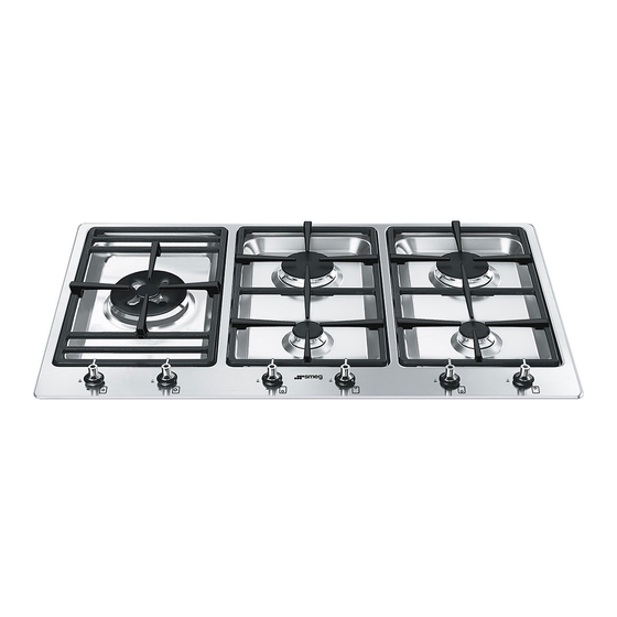
Page 8: Description
Description 2 Description 2.1 General Description 1. Control panel 2.2 Symbols 2. Auxiliary Burner (AUX) Cooking zones 3. Reduced Rapid Burner (RR) 4. Ultra-rapid burner, internal crown (UR2 int.) Rear 5. Ultra-rapid burner, external crown (UR2 ext.) 8. Right side trivet 7. -
Page 9: Available Accessories
Description Burner knobs Useful for lighting and adjusting the cooktop The ring reducer must be positioned above burners. Press and turn the knobs anti- the cooktop trivet as shown in the figure clockwise to the value to light the above. In any case, pans with a diameter greater relative burners. -
Page 10: Use
3 Use 3.2 First use 1. Remove any protective film from the 3.1 Instructions outside or inside of the appliance, including accessories. Improper use 2. Remove any labels (apart from the Danger of burns technical data plate) from accessories. 3. Remove and wash all the appliance •... - Page 11 Positioning the trivets Practical tips for using the cooktop The trivets are provided unassembled on For better burner efficiency and to minimise the cooktop. Follow the instructions as gas consumption, use pans with lids and of shown in the figure for correct trivet suitable size for the burner, so that flames positioning.
- Page 12 Limitations on griddle use A few precautions are necessary if you wish to use a griddle: • Griddles must not protrude beyond the perimeter of the cooktop • Aluminium griddles with Teflon anti-stick coating should be pre-heated for a maximum of 5 minutes in order to avoid damage to the appliance and the Teflon coating.
-
Page 13: Cleaning And Maintenance
Cleaning and maintenance 4 Cleaning and maintenance Food stains or residues Do not use steel sponges or sharp scrapers 4.1 Instructions as they will damage the surfaces. Use ordinary non-abrasive products with Improper use the aid of wooden or plastic utensils if Risk of damage to surfaces necessary. - Page 14 Cleaning and maintenance Flame-spreader crowns and burner caps Igniters and thermocouples For correct operation the igniters and For easier cleaning, the flame-spreader crowns and the burner caps can be thermocouples must always be perfectly removed. Wash them in hot water and non- clean.
-
Page 15: Installation
Installation 5 Installation 5.1 Clearances above and around domestic appliances This appliance must be installed by an part of the cooktop shall be protected for authorised person in accordance with this the full width and depth of the cooking instruction manual, AS/NZS 5601.1 – surface area in accordance with Clause Gas installations (installation and pipe 5.12.1.2. -
Page 16: Safety Instructions
Installation 5.2 Safety instructions 3. Additional requirements for Freestanding and Elevated Cooking Heat production during appliance Appliances – (Measurements D & E) operation Where D, the distance from the Risk of fire periphery of the nearest burner to a horizontal combustible surface is less •... -
Page 17: Positioning In The Counter Top
Installation 5.3 Positioning in the counter top To prevent leakage of liquid between the frame of the cooktop and the worktop, The following operation requires carefully position the insulating seal building and/or carpentry work provided before assembly (E). and must therefore be carried out 1. - Page 18 Installation 2. Place the cooktop on the insulating seal Fixing to the flush built-in model support structure and fix it to the supporting structure using the supplied screws and fastening Create an opening with the dimensions brackets (A) so that the cooktop is shown in the figure in the work surface of perfectly flat.
- Page 19 Installation After performing these operations, fasten the appliance in place with the dedicated brackets supplied (A) in order to achieve a perfectly flush mount, per the instructions shown in the figure. This built-in model requires a 3 mm deep section to be routed out of the worktop (detail “B”...
- Page 20 Installation Dimensions: gas and electrical connection • For fixing this product to the location (measurements in mm) support structure, you are advised not to use mechanical or electrical screwdrivers and to exert moderate manual pressure on the fastening elements. • It is advisable to use the supplied brackets in all the fixing points.
-
Page 21: Mounting
Installation 5.4 Mounting Over empty kitchen unit or drawers If there are other pieces of furniture (side Over built-in oven walls, drawers etc.), dishwashers or fridges The distance between the cooktop and the under the cooktop, a double-layer wooden kitchen furniture or other installed base must be installed at least 10 mm from appliances must be enough to ensure the bottom of the cooktop to avoid any... -
Page 22: Gas Connection
Installation 5.5 Gas connection Connection of the appliance to the gas supply must be in accordance with the Gas leak requirements of AS5601. A ½” BSP Danger of explosion connector at the inlet is recommended and the gas supply line to the appliance must be of adequate length to allow sufficient •... - Page 23 Installation To check the operating pressure of the Connection to LPG appliance it is recommended at least 2 Use a pressure regulator and make the large size burners are used. Ensure connection on the gas cylinder following appliance is secured to wall when the guidelines set out in the regulations in installation is completed.
- Page 24 Installation Room ventilation The appliance should be installed in rooms that have a permanent air supply in accordance with the standards in force. The room where the appliance is installed must have enough air flow needed for the regular combustion of gas and the necessary air change in the room itself.
-
Page 25: Adaptation To Different Types Of Gas
Installation 5.6 Adaptation to different types of 3. Use a 7 mm socket wrench to unscrew the burner injectors, then replace them with a new injector suitable for the type In case of operation with other types of gas, of gas to be used (see “Burner and the burner injectors must be changed and injector characteristics table”). - Page 26 Installation Adjusting the minimum setting for natural 5. Turn the knob rapidly from the maximum or city gas to the minimum setting: the flame should not go out. Repeat the operation on all 1. Light the burner and turn it to the minimum gas valves position.
-
Page 27: Electrical Connection
Installation Burner and injector characteristics tables NG 1.0 kPA UR2 Int. UR2 Ext. Nominal gas consumption (MJ/h) 16.8 Injector (1/100 mm) ULPG 2.75 kPa UR2 Int. UR2 Ext. Nominal gas consumption (MJ/h) .9.6 18.3 Injector (1/100 mm) 5.7 Electrical connection General information Check the grid characteristics against the Power voltage... -
Page 28: Instructions For The Installer
Installation 5.8 Instructions for the installer The appliance can work in the following modes: • The plug must be accessible after • 220-240 V 1N~ installation. Do not bend or trap the electrical power cable. • The appliance must be installed according to the installation diagrams.
Need help?
Do you have a question about the PSA906-5 and is the answer not in the manual?
Questions and answers