Table of Contents
Advertisement
Quick Links
These instructions apply only to the destination countries listed on the appliance's data
plate.
This is a class 3 built-in hob.
We advise you to read this manual carefully, as it contains all the instructions for maintaining
the appliance's aesthetic and functional qualities.
For further information on the product: www.smeg.com
Table of contents
4
4
7
7
7
7
8
9
10
10
11
12
13
13
13
13
16
16
16
18
18
18
20
21
24
26
27
3
Advertisement
Table of Contents

Related Manuals for Smeg PGA96


Summary of Contents for Smeg PGA96
-
Page 1: Table Of Contents
These instructions apply only to the destination countries listed on the appliance's data plate. This is a class 3 built-in hob. We advise you to read this manual carefully, as it contains all the instructions for maintaining the appliance’s aesthetic and functional qualities. For further information on the product: www.smeg.com... -
Page 2: Instructions
Instructions 1 Instructions is in use. • WARNING: Unattended cooking 1.1 General safety instructions on a hob with fat or oil can be Risk of personal injury dangerous and may result in fire. • Cleaning and maintenance must • WARNING - Accessible parts not be carried out by unsupervised will become hot when in use. - Page 3 Instructions • Do not insert pointed metal Risk of damaging the appliance objects (cutlery or utensils) into the • This appliance is not intended to slots in the appliance. be operated by means of external • NEVER try to extinguish a fire with timer or separate remote control water, but switch off the appliance system.
- Page 4 Instructions zones. not be installed behind a decoration door or a panel. • Do not use harsh abrasive cleaners or sharp metal scrapers • Before any operation on the to clean glass since they can appliance (installation, scratch the surface, which may maintenance, positioning or result in shattering of the glass.
-
Page 5: Manufacturer Liability
Instructions solution, never with a flame. objects (cutlery or utensils) into the slots in the appliance. • Have the electrical connection performed by authorised • Do not use the appliance to heat technicians. rooms for any reason. • The appliance must be connected •... -
Page 6: Disposal
Instructions life of the appliance. Read this user • Our appliances are packaged in non-polluting and recyclable manual carefully before using the materials. appliance • Deliver the packing materials to 1.6 Disposal the appropriate recycling centre. This appliance conforms to the Plastic packaging WEEE European directive (2012/19/EU) and must be... -
Page 7: How To Read The User Manual
Instructions 1.7 How to read the user manual This user manual uses the following reading conventions: Instructions General information on this user manual, on safety and final disposal. Description Description of the appliance and its accessories. Information on the use of the appliance and its accessories. -
Page 8: Description
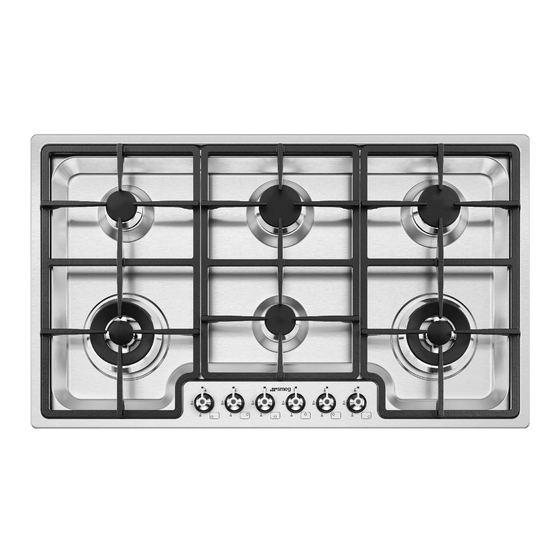
Description 2 Description 2.1 General Description 60 cm 70 cm... -
Page 9: Symbols
Description 90 cm 1 Control panel Front left 2 Auxiliary Burner (AUX) 3 Semi-Rapid burner (SR) Rear left 4 Reduced Rapid burner reduced (RR) 5 Ultra-Rapid triple crown burner (UR3) Front right 6 Ultra-Rapid double crown burner (UR2) 7 Left grid Rear right 8 Central grid 9 Right grid... -
Page 10: Available Accessories
Description Burner knobs Used for lighting and adjusting the hob burners. Press and turn the knobs anti- clockwise to in order to light the relative burners. Turn the knobs to the zone between the maximum and minimum setting to adjust the flame. Return the knobs to the position to turn off the burners. -
Page 11: Use
3 Use 2. Remove any labels (apart from the technical data plate) from accessories. 3.1 Instructions 3. Remove and wash all the appliance's accessories (see 4 Cleaning and Improper use maintenance). Danger of burns 3.3 Using the hob • Make sure that the flame-spreader All the appliance’s control and monitoring crowns are correctly positioned in their devices are located together on the front... - Page 12 Positioning the pan stands Correct positioning of the flame- spreader crowns and burner caps The pan stands are provided unassembled Before lighting the hob burners, check that on the hob. To install the grids correctly, the flame-spreader crowns are correctly in follow the instructions as shown in the place with their respective burner caps, figures.
- Page 13 To prevent burns or damage to the hob or Limitations on griddle use the counter top during cooking, all cookware or griddles must be placed inside the perimeter of the hob. A few precautions are necessary if you wish to use a griddle: •...
-
Page 14: Cleaning And Maintenance
Cleaning and maintenance 4 Cleaning and maintenance Food stains or residues Do not use steel sponges and sharp 4.1 Instructions scrapers, as they will damage the surfaces. Use normal, non-abrasive products and a Improper use wooden or plastic tool, if necessary. Rinse Risk of damage to surfaces thoroughly and dry with a soft cloth or a microfibre cloth. - Page 15 Cleaning and maintenance Flame-spreader crowns and burner caps Igniters and thermocouples For easier cleaning, the flame-spreader For correct operation the igniters and crowns and the burner caps can be thermocouples must always be perfectly removed. Wash them in hot water and non- clean.
-
Page 16: Installation
Installation 5 Installation 5.2 Positioning in the counter top The following operation requires 5.1 Minimum clearance to building and/or carpentry work combustible surface and must therefore be carried out by a competent tradesman. Installation can be carried out on various materials such as masonry, metal, solid wood or plastic laminated wood as long as they are heat resistant (>90°C). - Page 17 Installation 1. Refer to the dimensions in the figure, bearing in mind that the front and rear long sides must brush against the hole. 3. Place the hob on the insulating seal and fix it to the supporting structure using the supplied screws and fastening brackets (A) so that the hob is perfectly level.
-
Page 18: Mounting
Installation 5.3 Mounting • If necessary, do not fix the hob using silicone as this would make Over built-in oven unit it impossible to remove the hob The clearance between the hob and the without damaging it. kitchen furniture or other installed •... -
Page 19: Gas Connection
Installation 5.4 Gas connection Gas leak Danger of explosion • After carrying out any operation, check that the tightening torque of gas connections is between 10 Nm and opens on rear 15 Nm. Over empty kitchen unit or drawers • If required, use a pressure regulator that If there are other pieces of furniture (lateral complies with current regulations. - Page 20 Installation Connection of the appliance to the gas To check the operating pressure of the supply must be in accordance with the appliance it is recommended at least 2 requirements of AS5601. A ½” BSP large size burners are used. Ensure connector at the inlet is recommended and appliance is secured to wall when the gas supply line to the appliance must be...
- Page 21 Installation Room ventilation An efficient extraction system requires precision planning by a specialist qualified The appliance should be installed in rooms in this area and must comply with the that have a permanent air supply in positions and clearances indicated by the accordance with the standards in force.
-
Page 22: Adaptation To Different Types Of Gas
Installation 5.5 Adaptation to different types of In case of operation with other types of gas, the burner nozzles must be changed and the minimum flame adjusted on the gas taps. Changing the nozzles 1. Remove the grids from the hob. 2. - Page 23 Installation 3. Replace the burner nozzles using a 7 mm 3. Turn the regulating screw on the side of socket wrench according to the gas to the cock stem until a steady minimum be used (see "Nozzle and burner flame is achieved. specification tables").
-
Page 24: Electrical Connection
Installation Lubricating the gas taps Over time the gas taps may become difficult to turn and get blocked. Clean them internally and replace the lubrication grease. Lubrication of the gas cocks should be performed by a specialised technician. Burner and nozzle characteristics tables NG 1.0 kPa Rated heating capacity (MJ/h) 15.2... -
Page 25: Instructions For The Installer
Installation Fixed connection 5.7 Instructions for the installer • The plug must be accessible after Fit the power line with an omnipolar circuit installation. Do not bend or trap the breaker in compliance with installation power cable. regulations. The circuit breaker should be •...
Need help?
Do you have a question about the PGA96 and is the answer not in the manual?
Questions and answers