
Related Manuals for JLG 1030P


Summary of Contents for JLG 1030P
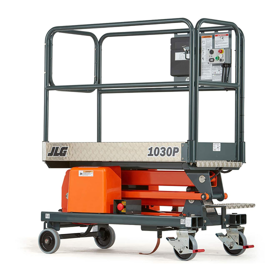
- Page 1 Operation and Safety Manual Original Instructions - Keep this manual with the machine at all times. Model 1030P ® ANSI 3121789 April 22, 2020 - Rev A...
- Page 2 WARNING Operating, servicing and maintaining this vehicle or equipment can expose you to chemicals including engine exhaust, carbon monoxide, phthalates, and lead, which are known to the State of California to cause cancer and birth defects or other reproductive harm. To minimize exposure, avoid breathing exhaust, do not idle the engine except as necessary, service your vehicle or equipment in a well-ventilated area and wear gloves or wash your hands frequently when servicing.
- Page 3 The purpose of this manual is to provide owners, users, operators, lessors, and lessees with the precautions and operating procedures essential for the safe and proper machine operation for its intended purpose. Due to continuous product improvements, JLG Industries, Inc. reserves the right to make specification changes without prior notification. Contact JLG Industries, Inc. for updated information.
- Page 4 FOREWORD SAFETY ALERT SYMBOLS AND SAFETY SIGNAL WORDS This is the Safety Alert Symbol. It is used to alert you to the potential personal injury hazards. Obey all safety messages that follow this symbol to avoid possible injury or death DANGER CAUTION INDI CATES A POTENTIALLY HA ZARDOUS SI TUATI ON.
- Page 5 Your Local JLG Office (See addresses on manual rear cover) JLG INDUSTRIES, INC. MUST BE NOTIFIED IMMEDIATELY IN ALL INSTANCES WHERE JLG PRODUCTS HAVE BEEN INVOLVED IN AN ACCI- In USA: DENT INVOLVING BODILY INJURY OR DEATH OR WHEN SUBSTANTIAL...
- Page 6 FOREWORD REVISION LOG Original Issue A - XX XX, 2020 3121789...
-
Page 7: Table Of Contents
TABLE OF CONTENTS SECTION - 1 - SAFETY PRECAUTIONS Machine Familiarization..... . 2-2 2.2 PREPARATION, INSPECTION, AND 1.1 GENERAL........1-1 MAINTENANCE . - Page 8 TABLE OF CONTENTS 3.6 EMERGENCY LOWERING VALVE ....3-8 Battery Charger ......5-2 3.7 TRANSPORTATION, LIFTING, AND TIE-DOWN Hydraulic Oil .
-
Page 9: Section 1 - Safety Precautions
• Read, understand, and obey all DANGERS, WARNINGS, CAUTIONS, and operating instructions on the machine and in this manual. • Ensure that the machine is to be used in a manner which is within the scope of its intended application as determined by JLG. 3121789... -
Page 10: Workplace Inspection
• Do not operate or raise the platform from a position on trucks, trailers, railway cars, floating vessels, scaffolds or other equipment unless the application is approved in writing by JLG. MODIFICATION OR ALTERATION OF A MEWP SHALL BE MADE ONLY WITH PRIOR WRITTEN •... -
Page 11: Operation
Remove the unit from service and notify the proper authorities. • JLG Industries, Inc. recommends all personnel in the platform wear • Do not remove, modify, or disable any safety devices. a fall/travel restraint system in the platform with a lanyard •... -
Page 12: Electrocution Hazard
SECTION 1 - SAFETY PRECAUTIONS Electrocution Hazard • Keep both feet firmly positioned on the platform floor at all times. Never position ladders, boxes, steps, planks, or similar items on unit to provide additional reach for any purpose. • This machine is not insulated and does not provide protection •... -
Page 13: Tipping Hazards
SECTION 1 - SAFETY PRECAUTIONS Tipping Hazards Table 1-1. Minimum Approach Distances (M.A.D.) VOLTAGE RANGE MINIMUM APPROACH DISTANCE (Phase to Phase) in Feet (Meters) 0 to 50 KV 10 (3) Over 50KV to 200 KV 15 (5) Over 200 KV to 350 KV 20 (6) Over 350 KV to 500 KV 25 (8) - Page 14 Keep all loads within the confines of the platform, unless authorized by JLG. • Never operate machine in high wind, rain, or snow. • Keep the chassis of the machine a minimum of 2 ft (0.6 m) from •...
-
Page 15: Crushing And Collision Hazards
SECTION 1 - SAFETY PRECAUTIONS Crushing and Collision Hazards • During operation, keep all body parts inside platform railing. • Keep non-operating personnel at least 6 ft (1.8 m) away from machine during all operations. • When moving the machine, the operator must limit travel speed according to conditions of ground surface, congestion, visibility, slope, location of personnel, and other factors. -
Page 16: Transporting
SECTION 1 - SAFETY PRECAUTIONS TRANSPORTING • Watch for obstructions around machine and overhead. Tipping Hazards FAILURE TO COMPLY WITH THE FOLLOWING TIPPING HAZARD INSTRUCTIONS COULD CAUSE THE UNIT TO TIP OVER OR BE HARD TO CONTROL WHEN BEING MOVED, WHICH COULD RESULT IN SERIOUS INJURY OR DEATH. - Page 17 SECTION 1 - SAFETY PRECAUTIONS • Two persons are required on slopes up to 5°. A forklift must be • Never position the unit sideways on a slope. used when moving units on slopes greater than 5°. • Do not elevate the platform or move the machine on a soft sur- •...
-
Page 18: Moving, Lifting And Repositioning
SECTION 1 - SAFETY PRECAUTIONS MOVING, LIFTING AND REPOSITIONING MAINTENANCE General This sub-section contains general safety precautions which must be observed during maintenance of this machine. Additional precau- • Never allow personnel in platform while moving, lifting or reposi- tions to be observed during machine maintenance are inserted at tioning the machine. -
Page 19: Battery Hazards
• Do not contact tools or other metal objects across the battery ter- minals. • Use only replacement parts or compo- nents that are approved by JLG. To be • Always wear hand, eye, and face protection when servicing batter- considered approved, replacement parts ies. - Page 20 SECTION 1 - SAFETY PRECAUTIONS NOTES: 1-12 3121789...
-
Page 21: Section 2 - Preparation And Inspection
SECTION 2 - PREPARATION AND INSPECTION SECTION 2. PREPARATION AND INSPECTION PERSONNEL TRAINING Means to avoid the hazards of unprotected electrical con- ductors. The Mobile Elevating Work Platform (MEWP) is a personnel handling Selection of the appropriate MEWPs and available options device, so it is necessary that it be operated and maintained only by for the work to be performed considering specific job trained personnel. -
Page 22: Machine Familiarization
Responsibilities for familiarization may vary by region. The Inspection and Maintenance Table covers the machine inspec- tions and maintenance recommended by JLG Industries, Inc. Con- Only properly trained personnel who have received unit-specific sult local regulations for further requirements for aerial work familiarization shall operate a MEWP. -
Page 23: Inspection And Maintenance Table
Inspection forms are available from JLG. Use the Service and Maintenance Manual to perform inspections. NOTICE JLG INDUSTRIES, INC. RECOGNIZES A FACTORY-TRAINED SERVICE TECHNICIAN AS A PERSON WHO HAS SUCCESSFULLY COMPLETED THE JLG SERVICE TRAINING SCHOOL FOR THE SPECIFIC JLG PRODUCT MODEL. -
Page 24: Pre-Start Inspection
Keep gate closed at all times except when entering/exiting the platform and loading/unloading mate- rials. Lanyard Attach Points – JLG Industries, Inc. recommends personnel in the platform wear a fall/travel restraint system with a lanyard attached to an authorized lanyard attach point. -
Page 25: Walk-Around Inspection
SECTION 2 - PREPARATION AND INSPECTION WALK-AROUND INSPECTION OAD00420 3121789... - Page 26 SECTION 2 - PREPARATION AND INSPECTION Begin the Walk-Around Inspection at item 1. Continue around Bubble Level Indicator - Ensure bubble level indicator is machine and check each item on this list. clean, secure, and responsive to movement. Gate/Gate Latch - Entry gate swings freely when opened; NOTICE closes and latches properly when closed.
-
Page 27: Function Check
SECTION 2 - PREPARATION AND INSPECTION FUNCTION CHECK With the aid of an assistant, check the operation of the rear wheel auto-locking brake mechanism: Perform a function check of all systems in an area free of overhead a. Elevate the platform so it is clear of the chassis. and ground level obstructions. - Page 28 SECTION 2 - PREPARATION AND INSPECTION NOTES: 3121789...
-
Page 29: Section 3 - Machine Operation
SECTION 3 - MACHINE OPERATION SECTION 3. MACHINE OPERATION 3.1 GENERAL MACHINE DESCRIPTION The machine is manually propelled machine with a work platform NOTICE mounted to an elevating armstack assembly. This machine’s intended purpose is to provide personnel (with their tools & sup- THE MANUFACTURER HAS NO DIRECT CONTROL OVER MACHINE APPLICATION AND OPER- plies) access to areas above ground level. -
Page 30: Operating Characteristics And Limitations
Load is within manufacturer’s rated capacity. All machine systems are functioning properly. Stability This machine, as originally manufactured by JLG and operated within its rated capacity on a smooth, firm surface, within the limits of the maximum operating slope, provides a stable aerial platform for all platform positions. -
Page 31: Machine Operation
If the indicator displays red, battery volt- age is low and should be charged before operating machine. NOTICE JLG RECOMMENDS THAT THE OPERATOR UTILIZES A FALL RESTRAINT SYSTEM IN THE PLATFORM WITH A LANYARD ATTACHED TO THE AUTHORIZED LANYARD ANCHORAGE POINT IN THE PLATFORM. - Page 32 SECTION 3 - MACHINE OPERATION At the ground control box, the battery charge indicator displays a Battery charge level is also indicated by LEDs on the battery charger. series of red LEDs. One LED illuminates at a time to indicate battery Plug in the charger to an available power supply.
-
Page 33: Positioning And Leveling Machine
SECTION 3 - MACHINE OPERATION Positioning and Leveling Machine Entering/Exiting the Platform DO NOT EXCEED MAXIMUM PLATFORM CAPACITY. MAXIMUM CAPACITY INCLUDES PER- SONNEL IN PLATFORM PLUS WEIGHT IN TOOL TRAY OR ANY OTHER WEIGHT PLACED IN PLATFORM. Always maintain “three point contact” with the machine by using two hands and one foot or two feet and one hand at all times during entry and exit. -
Page 34: Ground Control Panel
SECTION 3 - MACHINE OPERATION Ground Control Panel Overload Alarm - The alarm will sound if platform overload is detected. Overload Indicator - The indicator will flash if platform overload is detected. Battery Indicator - The indicator displays the current charge status of the battery. -
Page 35: Platform Control Panel
SECTION 3 - MACHINE OPERATION Platform Control Panel Overload Alarm - The alarm will sound if platform overload is detected. Overload Indicator - The indicator will flash if platform overload is detected. Hourmeter - Displays the number of hours the machine has been operated. -
Page 36: Emergency Lowering Valve
SECTION 3 - MACHINE OPERATION EMERGENCY LOWERING VALVE DO NOT CLIMB OUT OF THE PLATFORM WHILE ELEVATED. THIS MAY AFFECT THE MACHINE'S BALANCE AND CAUSE IT TO TIP OVER. ONLY EXIT THE PLATFORM THROUGH THE PLATFORM GATES. DO NOT ATTEMPT TO CLIMB DOWN ARM ASSEMBLY. In case of platform control failure or operator incapacity, use the emergency lowering valve. -
Page 37: Transportation, Lifting, And Tie-Down
SECTION 3 - MACHINE OPERATION TRANSPORTATION, LIFTING, AND TIE-DOWN NOTICE PROCEDURES NEVER PLACE THE STRAP THROUGH THE PLATFORM OR HANDRAILS. THIS COULD RESULT IN MACHINE DAMAGE. DO NOT USE EXCESSIVE FORCE WHEN TIGHTENING STRAPS. Loading or Towing Storage If loading machine up a ramp to the trailer with the aid of a winch, If the machine is to be taken out of operation for a period longer connect the winch cable to the castor/gate end of the chassis using than one month, the following precautions should be taken:... -
Page 38: Transportation Diagram
SECTION 3 - MACHINE OPERATION Transportation Diagram OAD00680 3-10 3121789... -
Page 39: Machine Decals
SECTION 3 - MACHINE OPERATION MACHINE DECALS 27 14 OAR00030 3121789 3-11... - Page 40 SECTION 3 - MACHINE OPERATION ANSI - English CSA - French ANSI - Spanish ANSI - Portuguese ANSI - English CSA - French ANSI - Spanish ANSI - Portuguese Item Item (1001243752-C) (1001244679-A) (1001244680-A) (1001244681-A) (1001243752-C) (1001244679-A) (1001244680-A) (1001244681-A) 1701509 1701509 1701509 1701509...
-
Page 41: Section 4 - Emergency Procedures
SECTION 4 - EMERGENCY PROCEDURES SECTION 4. EMERGENCY PROCEDURES GENERAL INFORMATION Platform Caught Overhead If the platform becomes jammed or snagged in overhead structures This section explains the steps to be taken in case of an emergency or equipment, do the following: situation while operating the machine. -
Page 42: Righting Of Tipped Machine
JLG Industries, Inc. must be notified immediately of any incident that may prevent it from sitting properly on its base wheels once in involving a JLG product. Even if no injury or property damage is evi- a vertical position, (i.e., base wheels damaged, base frame distorted, dent, JLG must be contacted by telephone and provided with all etc.). -
Page 43: Emergency Lowering Valve
SECTION 4 - EMERGENCY PROCEDURES EMERGENCY LOWERING VALVE DO NOT CLIMB OUT OF THE PLATFORM WHILE ELEVATED. THIS MAY AFFECT THE MACHINE'S BALANCE AND CAUSE IT TO TIP OVER. ONLY EXIT THE PLATFORM VIA THE PLATFORM GATES. DO NOT ATTEMPT TO CLIMB DOWN ARM ASSEMBLY. In case of platform control failure or operator incapacity, use the emergency lowering valve. - Page 44 SECTION 4 - EMERGENCY PROCEDURES NOTES: 3121789...
-
Page 45: Section 5 - Specifications & Operator Maintenance
SECTION 5 - SPECIFICATIONS & OPERATOR MAINTENANCE SECTION 5. SPECIFICATIONS & OPERATOR MAINTENANCE INTRODUCTION SERIAL NUMBER PLATE This section of the manual provides additional necessary informa- tion to the operator for proper operation and maintenance of this machine. The maintenance portion of this section is intended as information to assist the operator to perform daily maintenance tasks only. -
Page 46: Machine Specifications
SECTION 5 - SPECIFICATIONS & OPERATOR MAINTENANCE MACHINE SPECIFICATIONS DIMENSIONS General Length 5.31 ft (1.62m) WORKING SPECIFICATIONS Width 2.56 ft (0.78 m) Maximum Working Height 16.73 ft (5.10 m) Height 6.07 ft (1.85 m) Maximum Platform Height 10.17 ft (3.10 m) Power Source Weight 775 lb (352 kg) -
Page 47: Working Envelope
SECTION 5 - SPECIFICATIONS & OPERATOR MAINTENANCE OPERATOR MAINTENANCE Working Envelope Accessing Base Frame Components 16.4 ft (5.0 m) CAUTION BEFORE REMOVING BASE FRAME COVERS FOR MAINTENANCE PURPOSES, SWITCH OFF BATTERY ISOLATOR BESIDE THE BATTERY COMPARTMENT. USE APPROPRIATE SAFETY/ PERSONAL PROTECTIVE EQUIPMENT WHEN NECESSARY. 13.1 ft (4.0 m) 9.84 ft... -
Page 48: Battery
SECTION 5 - SPECIFICATIONS & OPERATOR MAINTENANCE Battery Battery Charger Plug in the charger to an available power supply. The LEDs will illu- minate in sequence. When the top LED is illuminated, charging is complete. To ensure the proper operation of the battery charger, verify the bottom LED illuminates when it is plugged in. -
Page 49: Hydraulic System
SECTION 5 - SPECIFICATIONS & OPERATOR MAINTENANCE Hydraulic System Hydraulic oil must be replaced on an annual basis, otherwise pre- mature wear and component failure may occur. Follow these guidelines when servicing the hydraulic system: • Check oil level only when the platform is fully lowered. •... -
Page 50: Lubrication
SECTION 5 - SPECIFICATIONS & OPERATOR MAINTENANCE Lubrication This machine has 12 pivots that must be lubricated with multipurpose grease on a monthly schedule. Use the following chart to determine pivot location. Remove the knuckle cover at the front end of the arm assembly to access three of the pivots. 3121789... -
Page 51: Wheels & Castors
SECTION 5 - SPECIFICATIONS & OPERATOR MAINTENANCE Wheels & Castors A simple measure of horizontal push force can determine the condi- tions of the wheel bearings. On a flat, smooth surface, the machine should move with a force of 9 - 10 kg when pushed from midrail. Wheels and castors must be in good conditions at all times because they stabilize the machine. - Page 52 SECTION 5 - SPECIFICATIONS & OPERATOR MAINTENANCE NOTES: 3121789...
- Page 53 SECTION 6 - INSPECTION AND REPAIR LOG SECTION 6. INSPECTION AND REPAIR LOG Machine Serial Number: _________________________ DATE COMMENTS 3121789...
- Page 54 SECTION 6 - INSPECTION AND REPAIR LOG Machine Serial Number: _________________________ DATE COMMENTS 3121789...
- Page 56 Corporate Office JLG Industries, Inc. 1 JLG Drive McConnellsburg, PA 17233-9533 USA (717) 485-5161 (Corporate) (877) 554-5438 (Customer Support) (717) 485-6417 Visit our website for JLG Worldwide Locations. www.jlg.com...
Need help?
Do you have a question about the 1030P and is the answer not in the manual?
Questions and answers