Table of Contents
Advertisement
Quick Links
Advertisement
Table of Contents

Related Manuals for AMGO Hydraulics XL-7


Summary of Contents for AMGO Hydraulics XL-7
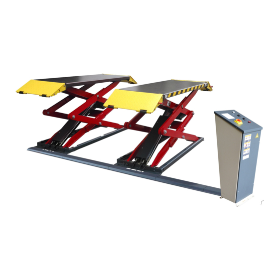
- Page 1 Original On-Surface Scissors Lift Model:XL-7...
-
Page 2: Table Of Contents
CONTENTS Product Features and Specifications ..........1 Installation Requirement .............3 Steps of Installation ………………………………………………..…………………….…...4 Exploded View .................14 Test Run .................22 Operation Instruction ..............23 Maintenance ................24 Trouble Shooting ..............25 ................25 Lift disposal... -
Page 3: Product Features And Specifications
I. PRODUCT FEATURES AND SPECIFICATIONS ON SURFACE SCISSORS LIFT MODEL XL-7 · Electric/Hydraulic power system · Hose burst check valve and hydraulic self-lock system · 2-Dual synchronous cylinders are applied to assure the lifting level on both platforms · Flow control valve to ensure the stable down speed ·... - Page 4 View B (Other option) Fig. 2...
-
Page 5: Installation Requirement
II. INSTALLATION REQUIREMENT A. TOOLS REQUIRED Rotary Hammer Drill Carpenter’s Chalk (Φ19, Φ10, Φ4) Hammer Screw Sets Level Bar Tape Measure (7.5m) English Spanner (12") Pliers Lock Wrench Wrench set # # 、17 ... -
Page 6: Steps Of Installation
Equipment storage and installation requirements. The equipment should be stored or installed in a shady, normal temperature, ventilated and dry place. The equipment should be unload and transfer by forklift. Fig. 4 D. POWER SUPPLY The electrical source must be 2.0HP minimum. - Page 7 2. Move aside the parts, open the outer packing and check the parts according to the shipment parts list (See Fig. 5) Platform Platform Fig. 6 Oil Hose 3. Open the parts box, check the parts according to the part list (See Fig.
- Page 8 4. Check the parts of the parts bag according to the parts bag list (See Fig.8) Fig. 8 B. Location of installation 1. Concrete must be thickness 6” minimum and without reinforcing steel bars, and must be dried completely before the installation. 2.
- Page 9 C. Equipment layout and oil hose installation Layout the equipment on the selected location according to , and connect the oil Fig 10 hose according to Fig.11 Note: Shutoff valves should be at the working condition( Fig. 30 29-1/2” Fig.10 Oil hose installation ○...
- Page 10 D. Install electric system 1. Wire connection for hydraulic power unit (for 220V/Single phase motor) 1.1 Connect the power wire and limit switch wire according to the wiring diagram (See Fig. 12). hydraulic Power Wire Earth Wire Limit switch Limit switch Motor Wire solenoid valve (Wire B)
- Page 11 Electric Component Item Name Code Specification Power switch 380V AC Breaker Breaker Breaker AC contactor 24V AC Limit switch ( ) Hydraulic solenoid valve (Right) AC 24V Hydraulic solenoid valve (Left) AC 24V Down Single Push button Lower Alarm Duplex Push Button Single Motor...
- Page 12 2.2 Lower alarm device instruction (See Fig.15) When the machine is lowered to 11-3/4”, the buffer connecting bar will access to the drive lever of limit switch, and stop the lift. Pushing Limit Switch the button Down while push the Lowering Alarm Button(black) at the side of control cabinet, the lift would be lowered down again with tone of alarm.
- Page 13 2. Anchor bolts installation 2.1 Lift the machine to 39-1/2” for the anchor bolt installation. Using the anchor bolt to fix the machine Fig. 17 2.2 Drilling the hole for the anchor bolt with the rotary hammer drill, type the anchor bolt into the ground, and then fasten it with Ratchet spanner.
- Page 14 F. Install oil hose cover and anchor the control cabinet 1. Tidy up the oil hose and wire, cover the oil hose cover and layout the control cabinet. (See Fig. 19, Fig 20) Tidy up the oil hose and wire, and then cover the oil hose cover Fig.
- Page 15 2. Install the colloidal screw of oil hose cover (See Fig. 21) Fig. 21 Type the expansion Fastening by Install Drilling Cleaning colloidal screw the steel screw 3. Install the control cabinet anchor bolt (See Fig. 22) Fig. 22 Drilling Cleaning Install screw Tighten...
-
Page 16: Exploded View
IV. EXPLODED VIEW MODEL XL-7 Fig. 23... - Page 17 PARTS LIST FOR XL-7 Item Part# Description QTY. Note 11620124 Pin For Drive-thru Ramp 10650024 Self locking nut 11620128 Drive-in Ramp 11620001B Platform 10620034 Rubber Pad 10610070 Rubber Pad 11620129 Support frame for Drive-in Ramp (Left) 10620018 Slider Block (white)
- Page 18 Item Part# Description QTY. Note 11620010B Buffer 10620064 Greasing Fitting 11620008A Buffer Connecting Pin 10620135 Washer 10610008 Snap ring 11620028A Connecting Pin For Upper Scissor (In) 10640109 Washer 11620027B Upper Scissor (In) 10620022 Self locking Nut 10203004A Bronze Bush 11620019A Scissors Pin 11620130 Support frame for Drive-in Ramp(Right)
- Page 19 4.1 Main CYLINDERS (10620012B) Grease Fig 24 Parts for Main cylinder Item Part# Description QTY. Note 10209078 25-1 Dust Ring 10217243 25-2 Y- Ring 10620047 25-3 Support Ring 11620192 25-4 Head Cap (Main) 10620171 25-5 O- Ring 10630027 25-6 O-Ring 11620051 25-7 Piston Rod...
- Page 20 (10620186) 4.2. Secondly Cylinders Grease Fig.25 Parts for Secondly cylinder Item Part# Description QTY. Note 22-1 10520058 O- Ring 22-2 10201034 Bleeding Plug 22-3 11620190 Head Cap 22-4 10620182 O- Ring 22-5 11620056 Bore Weldment 22-6 11620196 Piston 22-7 10217258 O- Ring 22-8 10217257...
- Page 21 4.3 CONTROL CABINET 10620199 ) Fig. 26 Parts for control cabinet Item Part# Description QTY. Note 50-1 1162K001A Cabinet Body 50-2 10202046 Breaker 2P (220V only) 50-3 10202049 Breaker 1P 50-4 10420084A 24V AC Contractor (KM) 50-5 10420134 24V Transformer (TC) 50-6 10202051 Breaker 1P...
- Page 22 4.4 ELECTRIC POWER UNIT (071203) 220V/60HZ/1 Phase Fig. 27...
- Page 23 Parts for 220V 60Hz 1PH power unit Item Part# Description QTY. Note 81400180 Rubber Pad 81400130 Start Capacitor 81400088 Run Capacitor 10420148 Cup Head Bolt 81400066 Capacitor Cover 81400363 Motor Connecting Shaft 80101015 Valve Body 81400333 Socket Plug 81400266 Relief Valve 81400566 Check Valve 81400420...
-
Page 24: Test Run
V. TEST RUN 1. Turn on the power after connecting oil system correctly. Push the UP button, and check the rotated direction of the Motor (This is right if lift is upward, otherwise, it is wrong direction of the Motor). Shut off power and exchange the phase connection if the direction is wrong. -
Page 25: Operation Instruction
Down↓ e. Once the lift cannot be lowered from the highest position when press during idling test , Turn the 2 shutoff valves quickly into oil filling position (fig 28), then quickly to normal working position ( fig 29). Note: This operation of turning the handles should be finished quickly. VI. -
Page 26: Maintenance
Panel Lock Power Indicator Down Buzzer Lower Alarm Button(pass) Fig. 30 VII. MAINTENANCE SCHEDULE Monthly: 1. Re-torque the anchor bolts to 150Nm. 2. Lubricate all moving parts with lubricant. 3. Check all fittings, bolts and pins to insure proper mounting. 4. -
Page 27: Trouble Shooting
VIII. TROUBLE SHOOTING TROUBLE CAUSE REMEDY 1. Button does not work 1. Replace button 2. Wiring connections are not in good 2. Repair all wiring connection Motor does not run condition or disconnection 3. AC contactor in damage 3. Repair or Replace AC contactor 4. - Page 28 AMGO HYDRAULIC CORPORATION 1931 Joe Rogers Blvd, Manning, South Carolina, USA Zip: 29102 Tel: (803) 505-6410 Fax: (803) 505-6410 Manual no:72167204 Revised date:2019/12...
Need help?
Do you have a question about the XL-7 and is the answer not in the manual?
Questions and answers