Advertisement
Quick Links
Advertisement

Related Manuals for AMGO Hydraulics LR10


Summary of Contents for AMGO Hydraulics LR10
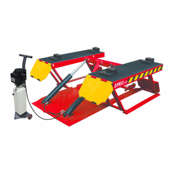
- Page 1 Original Portable Low-rised scissors lift Model:LR10...
-
Page 2: Table Of Contents
CONTENTS Product Features and Specifications ............1 Installation Requirement ................2 Step of Installation .................. 3 Exploded View ..................7 Operation Instructions ................12 Maintenance Schedule ................14 Trouble Shooting ..................15 Lift disposal ....................15... -
Page 3: Product Features And Specifications
I. PRODUCT FEATURES AND SPECIFICATIONS (See Fig.1) PORTABLE LOW-RISED MODEL LR10 · Self-locking safety device: 3 stage safety lock, mechanical lock, automatic release. · Portable unit is easy to move with the power unit stand. · Double cylinder design. · Multifunctional drive-in ramp, can also used as extension platform. -
Page 4: Installation Requirement
II. INSTALLATION REQUIREMENT A. Tools requirement Screw Set Grease gun Pliers Socket Head Wrench (8″) Wrench sets # # # # :(13 、15 、17 、19 Fig.2 B. Power requirement The electrical source must be 2.2KW minimum. The source cable size must be 2.5mm²... -
Page 5: Step Of Installation
III. STEPS OF INSTALLATION A. Check the parts before assembly, make sure all the parts are completed. Packaged lift, Parts box, Power Unit and Power Unit Stand. Move aside the parts, Open the outer packing and check the parts according to the shipment parts list (See Fig. - Page 6 Check the parts of the parts bag according to the parts bag list (See Fig. 5) Fig. 5 B. Install hydraulic power unit (See Fig. 6) Fig. 6...
- Page 7 C. Install fitting to power unit, and then connecting oil hose (See Fig.7). Fig. 7...
- Page 8 D. Install electrical system Connect the power source on the data plate of power unit. Note: 1. For the safety of operators, the power wiring must contact the floor well. 2. Pay attention to the direction of rotations when using three phrases motors.
-
Page 9: Exploded View
IV. EXPLODED VIEW MODEL LR10 Rollers Fig. 9... - Page 10 PARTS LIST FOR MODEL LR10 Note Item Part# Description QTY. 11630001A Platform 10206019 Snap Ring φ19 11630003 Pin for drive-in ramp φ19*452 11630106 Bracket Pin φ19*410 11620006A Bracket 11630108 Drive-in ramp 10209010 Snap Ring φ10 11620043 Roller Pin for drive-in ramp...
- Page 11 Note Item Part# Description QTY. Parts for Roller 20-1 11630031 Rollers handle 20-2 10630032 Snap Ring 20-3 11630033 Connecting Shaft 20-4 11630034 Roller Shaft 20-5 10640023 Roller Cylinder Fig. 10 Item Part No. Description QTY. Note 11630029 Bore Weldment 11630026 Piston Rod 10201034 Bleeding Plug...
- Page 12 Manual Power Unit (071101) Fig. 11...
- Page 13 Manual Power Unit 220V/50/60HZ Single Phase Item Part No. Description QTY. Note 81400180 Rubber Pad 81400130 Starting capacitor 81400088 Running capacitor 10420148 Cup head bolts with washer 81400066 Cover for capacity 81400363 Motor Connecting Shaft 090106 Manifold Block 10209149 Lock Washer 81400276 Plug 81400259...
-
Page 14: Operation Instructions
Illustration of hydraulic valve for power unit Protective ring Relief valve Oil return port Release valve Handle for release valve Throttle valve Oil Outlet Check valve Fig. 12 V. OPERATION INSTRUCTIONS 1. Install the oil hose between oil cylinder and power unit, connect well the power supply wire. - Page 15 5. Move lift: Pull up roller bracket, lock two roller to the lift with roller shaft. Moving the lift by the power unit stand. (See Fig. 15& 16 ). Roller Assy. disengaged Roller Assy. engaged Fig. 15 Fig. 16 5. There are four fixed holes in the machine, can fix the machine on ground by 3/4 X 4 3/4”...
-
Page 16: Maintenance Schedule
VI. MAINTENANCE SCHEDULE Monthly: 1. Lubricate all moving parts with lubricant. 2. Check all connectors, bolts and pins to insure proper mounting. 3. Make a visual inspection of all hydraulic hoses/lines for possible wear or leakage. Every six months: 1. 1. Make a visual inspection of all moving parts for possible wear, interference or damage. -
Page 17: Trouble Shooting
VII. TROUBLE SHOOTING TROUBLE CAUSE REMEDY 1. Start Button does not work 1. Replace Start button 2. Wiring connections are not in good 2. Repair all wiring connections Motor does not condition 3. Motor burned out 3. Repair or replace motor 4. - Page 18 Manual Part No. : 72106503 Revision Date: : 2020/08...
Need help?
Do you have a question about the LR10 and is the answer not in the manual?
Questions and answers