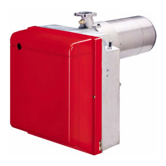
Riello RS5 Installation, Use And Maintenance Instructions
Forced draught gas burner
Hide thumbs
Also See for RS5:
- Installation, use and maintenance instructions (76 pages) ,
- Installation, use and maintenance instructions (52 pages)
Table of Contents
Advertisement
Available languages
Available languages
Quick Links
Advertisement
Table of Contents

Related Manuals for Riello RS5


Summary of Contents for Riello RS5
- Page 1 Istruzioni per installazione, uso e manutenzione Installation, use and maintenance instructions Bruciatore di gas ad aria soffiata Forced draught gas burner Funzionamento monostadio One stage operation CODICE - CODE MODELLO - MODEL TIPO - TYPE 20019993 920T2 20020956 (1) - 02/2010...
-
Page 2: Table Of Contents
INDICE DESCRIZIONE DEL BRUCIATORE ..........1.1 Materiale a corredo . -
Page 3: Descrizione Del Bruciatore
DESCRIZIONE DEL BRUCIATORE Bruciatore di gas con funzionamento monostadio. Il bruciatore risponde al grado di protezione IP X0D (IP 40) secondo EN 60529. Conforme alle Direttive: CEM 89/336/CEE - 2004/108/CE, Bassa Tensione 73/23/CEE - 2006/95/CE e Macchine 98/37/CEE. ... -
Page 4: Dati Tecnici
DATI TECNICI DATI TECNICI TIPO 920T2 Potenza termica (1) 330 kW 137.600 283.800 kcal/h Pci: 8 12 kWh/Nm = 7000 10.340 kcal/Nm Gas naturale (Famiglia 2) Pressione: min. 20 mbar max. 100 mbar ± Alimentazione elettrica Monofase, 230 V 50Hz Motore... -
Page 5: Campi Di Lavoro
CAMPO DI LAVORO, (secondo EN 676) 130.000 170.000 210.000 250.000 290.000 kcal/h Potenza termica D6231 CALDAIE DI PROVA Il campo di lavoro è stato ottenuto su caldaie di prova secondo norma EN 676. CALDAIE COMMERCIALI L’abbinamento bruciatore-caldaia non pone problemi se la caldaia è conforme alla norma EN 303 e le dimensioni della sua camera di combustione sono prossime a quelle previste nella norma EN 676. -
Page 6: Installazione
INSTALLAZIONE L’INSTALLAZIONE DEL BRUCIATORE DEVE ESSERE EFFETTUATA IN CONFORMITÀ ALLE LEGGI E NORMATIVE LOCALI. POSIZIONE DI FUNZIONAMENTO Il bruciatore è predisposto esclusi- vamente per il funzionamento nella posizione 1. Le installazioni nelle posizioni 2, 3, 5, 6, 7 non garantiscono la chiusura della serranda aria in sosta. -
Page 7: Rampa Gas
RAMPA GAS, (secondo EN 676) La rampa gas viene fornita a parte e per la sua regolazione vedere le istruzioni che l’accompagnano. RAMPA GAS ATTACCHI IMPIEGO TIPO CODICE INGRESSO USCITA Gas naturale 200kW e GPL 160 330 kW MBDLE 410 B01 3970549 Rp 1 1/4 Flangia 3... -
Page 8: Collegamenti Elettrici
COLLEGAMENTI ELETTRICI Non scambiare il neutro con la fase, rispettare esattamente lo schema indicato ed ese- guire un buon collegamento di terra. La sezione dei conduttori deve essere di min. 1 mm . (Salvo diverse indicazioni di norme e leggi locali). - Page 9 Fig. 7 20020956...
-
Page 10: Funzionamento
FUNZIONAMENTO POTENZA ALL’ACCENSIONE Fig. 8 L’accensione deve avvenire a potenza ridotta e non superiore ai 120 kW. Per misurare la potenza all'accensione: – Scollegare il connettore (CN1) sul cavo della son- da di ionizzazione (vedi collegamenti elettrici a pag. 7); il bruciatore si accende e va in blocco dopo il tempo di sicurezza (3s). -
Page 11: Regolazione Serranda Aria
ESTRAZIONE GRUPPO TESTA, (vedi fig. 8, pag. 9) Per l’estrazione del gruppo testa eseguire le seguenti operazioni: Estrarre il gruppo porta testa (1) dopo aver tolto le viti (7), sconnesso i collegamenti (3 e 5), sfilato il tubetto (4) e allentato le viti (10). Si raccomanda di non alterare la posizione di regolazione staffa–gomito nella fase di smontaggio RIMONTAGGIO GRUPPO TESTA, (vedi fig. -
Page 12: Controllo Della Combustione
CONTROLLO DELLA COMBUSTIONE È consigliabile regolare il bruciatore, a seconda del tipo di gas utilizzato, secondo le indicazioni fornite nella tabella seguente: ECCESSO D’ARIA: potenza max. 1,2 – potenza min. 1,3 EN 676 max. teorico Taratura CO ... -
Page 13: Sbocco Apparecchiatura
4.8 SBLOCCO APPARECCHIATURA Per effettuare lo sblocco dell’apparecchiatura procedere come segue: Premere il pulsante di sblocco per almeno 1 secondo. Nel caso in cui il bruciatore non riparta è necessario verificare la chiusura del termostato limite (TL). MANUTENZIONE Prima di effettuare qualsiasi operazione di pulizia o controllo, togliere l’alimentazione elettrica al bru- ciatore agendo sull’interruttore generale dell’impianto e chiudere la valvola di intercettazione del gas. -
Page 14: 5.1 Diagnostica Visiva Apparecchiatura
5.1 DIAGNOSTICA VISIVA APPARECCHIATURA L’apparecchiatura in dotazione ha una sua funzione diagnostica attraverso la quale è possibile facilmente individuare le possibili cause di mal funzionamento (segnalazione: LED ROSSO). Per utilizzare tale funzione, bisogna aspettare almeno dieci secondi dall’istante di messa in sicurezza dell’apparecchiatura e premere il pulsante di sblocco per un tempo minimo di tre secondi. -
Page 15: Anomalie / Rimedi
ANOMALIE / RIMEDI Si elencano alcune cause e i possibili rimedi a una serie di anomalie che potrebbero verificarsi e portare ad un mancato o non regolare funzionamento del bruciatore. Un’anomalia, nel funzionamento nella maggior parte dei casi, porta alla accensione della segnalazione all’interno del pulsante di sblocco dell’apparecchiatura di comando e controllo (5, fig. - Page 16 ANOMALIE POSSIBILE CAUSA RIMEDIO Verificare la pressione in rete e/o re- Le elettrovalvole fanno passare golare l’elettrovalvola come indicato in troppo poco gas. questo manuale. Le elettrovalvole sono difettose. Procedere ad una loro sostituzione. bruciatore blocco dopo la fase di Verificare il corretto inserimento dei preventilazione per-...
-
Page 17: Avvertenze E Sicurezza
AVVERTENZE E SICUREZZA Al fine di garantire una combustione col minimo tasso di emissioni inquinanti, le dimensioni ed il tipo di ca- mera di combustione del generatore di calore, devono corrispondere a valori ben definiti. È pertanto consigliato consultare il Servizio Tecnico di Assistenza prima di scegliere questo tipo di brucia- tore per l’abbinamento con una caldaia. - Page 18 INDEX BURNER DESCRIPTION ............1.1 Burner equipment .
- Page 19 BURNER DESCRIPTION One stage gas burner. The burner meets protection level of IP X0D (IP 40), EN 60529. According to directives: EMC 89/336/EEC - 2004/108/EC, Low Voltage 73/23/EEC - 2006/95/EC and Machines 98/37/EEC. Gas train according to EN 676. ...
- Page 20 TECHNICAL DATA TECHNICAL DATA TYPE 920T2 Thermal power (1) 160 – 330 kW – 137.600 283.800 kcal/h Net heat value: 8 – 12 kWh/Nm = 7000 – 10,340 kcal/Nm Natural gas (Family 2) Pressure: min. 20 mbar max. 100 mbar ±...
- Page 21 2.3 FIRING RATE (as EN 676) D6231 130.000 170.000 210.000 250.000 290.000 kcal/h Thermal power TEST BOILER The firing rate has been defined according to EN 676 standard. COMMERCIAL BOILERS The burner-boiler matching is assured if the boiler is according to EN 303 and the combustion chamber dimensions are similar to those shown in the diagram EN 676.
- Page 22 INSTALLATION THE BURNER MUST BE INSTALLED IN CONFORMITY WITH LEGISLATION AND LOCAL STANDARDS. WORKING POSITION The burner is designed for opera- tion in position 1 only. Installation in positions 2, 3, 5, 6 and 7 is not recommended as it is likely to hinder the unit’s proper operation since air damper closure cannot be guaranteed when the...
- Page 23 3.3 GAS TRAIN, (as EN 676) The gas train is supplied separately, for its adjustment see the enclosed instructions. GAS TRAIN CONNECTIONS TYPE CODE INLET OUTLET Natural gas 200kW and LPG 160 – MBDLE 410 B01 3970549 Rp 1 1 / 4 Flange 3 330 kW Natural gas ...
- Page 24 ELECTRICAL WIRING Do not swap neutral and phase over, follow the diagram shown carefully and carry out a good earth connection. 1 mm The section of the conductors must be at least . (Unless requested otherwise by local standards and legislation).
- Page 25 Fig. 7 20020956...
- Page 26 WORKING FIRING OUTPUT Fig. 8 The firing must occur at reducer output and not higher than 120 kW. In order to measure the firing output: – Disconnect the connector (CN1) on the ionization probe cable (see electrical wiring at page 7); the burner will fire and then go into lock-out after the safety time (3s) has elapsed.
- Page 27 HEAD ASSEMBLY REMOVING, (see fig. 8, page 9) To remove the head assembly, carry out the following operations: Remove the head-older assembly (1), after taking away the screws (7), disconnect the connections (3 and 5), extract the small tube (4) and loose the screws (10). Do not modify the setting position of the bracket-elbow during the disassembly.
- Page 28 COMBUSTION CHECK It is advisable to set the burner according to the type of gas used and following the indications of the table: 1.2 1.3 AIR EXCESS: max. output – min. output EN 676 Theoretical max. CO Setting CO ...
- Page 29 4.8 CONTROL BOX RESET To carry out the control box reset, proceed as follows: Press the reset button for at least 1 second. In the event of the burner not restarting it is necessary to check if the limit thermostat (TL) is closed. MAINTENANCE Disconnect the electric supply to the burner by switching off the main power switch and close the gas shut-off valve before maintaining or checking the system.
- Page 30 5.1 OPERATING FAULT DIAGNOSTICS The control box has a self-diagnostic system, which easily allows identifying the operating faults (RED LED signal). To use this function, wait at least ten seconds from the safety lock out, and then press the reset button for a minimum of 3 seconds.
- Page 31 FAULTS / SOLUTIONS Below are some examples of causes & possible solutions that could result in the burner failing to operate or that result in it working incorrectly. A fault usually makes the lock-out lamp light which is situated inside the reset button of the control box (5, fig.
- Page 32 FAULTS POSSIBLE CAUSES SOLUTION Check the supply pressure from the net- The solenoid valves is passing too lit- work & adjust the gas multibloc valve tle gas. according to the instructions. The solenoid valves are defective. Replace the valve bloc. The burner locks out Check the right insertion of the connec- a f t e r t h e p r e p u r g e...
- Page 33 SAFETY WARNINGS The dimension of the boiler’s combustion chamber must respond to specific values, in order to guarantee a combustion with the lowest polluting emissions rate. The Technical Service Personnel will be glad to give you all the imformation for a correct matching of this burner to the boiler.
- Page 34 RIELLO S.p.A. I-37045 Legnago (VR) Tel.: +39.0442.630111 http:// www.riello.it http:// www.rielloburners.com Con riserva di modifiche - Subject to modifications...
Need help?
Do you have a question about the RS5 and is the answer not in the manual?
Questions and answers