Advertisement
related literature |
003-794
004-048
001-059
LAN-307-EN
LAN-1550-AEN
1.
Carton Contents
a. EDgE Splice Cassette containing:
•
(12) 40 mm splice protectors (for single-fiber
installation)
•
(1) 40 mm splice protector (for ribbon
installation)
b. EDgE Field-Terminated Cassette
2.
Tools and Materials
•
Hook blade
•
Measuring tape
•
Scissors
•
4-in cable ties
•
900 µm tubing
•
Electrical tape
3.
Preparing the Cable
CAUTION: The wearing of cut-resistant safety gloves to protect your hands from accidental injury
when using sharp-bladed tools and armored cable is strongly recommended. Use extreme care
when working with severed armor. There will be a sharp edge where armor is cut. To minimize
the chance of injury from the cut armor, cover the exposed edge with a wrap of electrical tape. To
minimize the chance of injury from sharp-bladed tools, always cut away from yourself and others.
Dispose of used blades and armor scrap properly.
CAUTION: Recommend the use of safety glasses (spectacles) conforming to ANSI Z87, for eye
protection from accidental injury when handling chemicals, cables, or working with fiber. Pieces of
glass fiber are very sharp and have the potential to damage the eye.
CAUTION: Fiber optic cable is sensitive to excessive pulling, bending, and crushing forces.
Consult the cable specification sheet for the cable you are installing. Do not bend the cable more
sharply than the minimum recommended bend radius. Do not apply more pulling force to the
cable than specified. Do not crush the cable or allow it to kink. Doing so may cause damage that
can alter the transmission characteristics of the cable; the cable may have to be replaced.
STANDARD RECOMMENDED PROCEDURE 000-274 | ISSUE 4 | AUgUST 2016 | PAgE 1 OF 7
Instruction, EDgE™ Solution
Instruction, Accessing Individual Fibers in Ribbon Fiber Optic Cables with the
TKT-050 Kit
Instruction, Fiber Organizer Tape Applicator (FOTA) Operator Manual
Specification Sheet, Fiber Optic Splicing Tool Kits
Visual Installation Instruction, 250 µm Fiber
OR
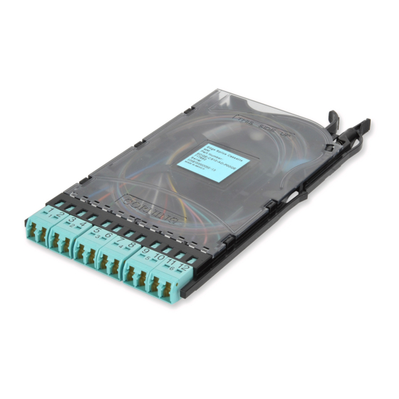
EDgE™ Splice Cassette/
EDgE™ Field-Terminated
Cassette
000-274, Issue 4
TPA-4067
For Ribbon Installation:
•
1/4-in braided tubing
(p/n 06-710-27)(optional)
•
Friction tape
For Single-fiber Installation
•
Miller
three-hole stripping tool
®
•
Ring cutting tool (p/n 3204002-01)
Advertisement
Table of Contents

Related Manuals for CORNING EDGE Splice Cassette

Summary of Contents for CORNING EDGE Splice Cassette
- Page 1 Instruction, Fiber Organizer Tape Applicator (FOTA) Operator Manual LAN-307-EN Specification Sheet, Fiber Optic Splicing Tool Kits LAN-1550-AEN Visual Installation Instruction, 250 µm Fiber Carton Contents a. EDgE Splice Cassette containing: • (12) 40 mm splice protectors (for single-fiber installation) • (1) 40 mm splice protector (for ribbon installation) b.
- Page 2 NOTE: This procedure assumes that the EDgE™ solution housing is on a work surface or has been installed into the frame. Total Outer Jacket Fiber Inside Cassette Jacketed Subunit Strip Length For Splicing 33 in 33 in 66 in Strip jacket(s) per lengths specified in table above for your application. (Optional) If cable is ribbon or single-fiber, install 33 inches (0.84 m) of braided or protective tubing, leaving length required for splicing inside the...
- Page 3 Corning Optical Communications Standard Recommended Procedure (SRP) SRP-004-048. 2) If ribbonizing the cable is required for splicing, refer to Corning Optical Communications Specification sheet LAN-307-EN for TKT-026-01A kit description. For Fiber Organizer Tape Applicator (FOTA) operator manual, refer to SRP-001-059.
- Page 4 Polarity Management (for Splice Cassette) Polarity management is critical during the splicing process. Corning Optical Communications offers two different splice cassette wiring options: Straight Through or Universal Wiring. Figure 5 depicts the way the ribbon fibers should be spliced in order to achieve the polarity management desired.
- Page 5 • When using 250 µm fiber, use a short section of 900 µm tubing instead of a connector boot immediately behind the connector. Refer to Corning Visual Instruction LAN-1550-AEN for details. • It is recommended to use electrical tape to hold fibers properly in place while routing.
- Page 6 Step 6: Beginning with adapter 12, mate six connectors into adapters 7 through 12 and route the fibers as shown in Figure 7. Step 7: Then mate the last six connectors into adapters 1 through 6 and route the fibers as shown.
- Page 7 800-743-2675 • FAX: 828-325-5060 • International: +1-828-901-5000 • www.corning.com/opcomm Corning Optical Communications reserves the right to improve, enhance, and modify the features and specifications of Corning Optical Communications products without prior notification. A complete listing of the trademarks of Corning Optical Communications is available at www.corning.com/opcomm/trademarks. All other trademarks are the properties of their respective owners.
Need help?
Do you have a question about the EDGE Splice Cassette and is the answer not in the manual?
Questions and answers