
Related Manuals for NetBurner SB72EX

Summary of Contents for NetBurner SB72EX
- Page 1 B u r n e r SB72EX User's Manual Revision: 1.8 October 8, 2009 SB72EX User's Manual, 350030-001 Downloaded from Elcodis.com electronic components distributor...
-
Page 2: Table Of Contents
Table of Contents Table of Contents ....................... 2 Overview of the SB72EX Dual-port Serial to Ethernet Device........3 Overview of the SB72EX Dual-port Serial to Ethernet Device........3 Configuration ........................3 Hardware Configuration......................4 Operational Configuration......................6 Network Settings ........................ 6 Device Connection Settings (TCP mode) ................ -
Page 3: Overview Of The Sb72Ex Dual-Port Serial To Ethernet Device
3. Operational configuration You will need to tell your SB72EX what type of serial interface you want to use, the network address you want your SB72EX to respond to, the serial data baud rate, and the TCP/IP listening port number. -
Page 4: Hardware Configuration
To configure Port 0 as RS-422/485, you will need to open up your SB72EX case and change the position of the five jumpers. (Note: Please take proper ESD precautions. Failure to do so will void your NetBurner Standard Hardware Warranty.) - Page 5 Monitor port (screen shot below). 2. Locate your SB72EX in the "Select a Unit" pane by matching its MAC address. The MAC address is located on the bottom of your SB72EX. If your SB72EX device does not appear in the list box, verify the power, speed, and link LEDs are illuminated, and click the Search Again button.
-
Page 6: Operational Configuration
Once the network parameters have been configured, you can use the web server interface to modify the settings of your SB72EX. To access the web page on your SB72EX, click on the Launch Webpage button in IP Setup, or you can open your web browser, and enter the numeric IP Address in the address field (e.g. -
Page 7: Device Connection Settings (Tcp Mode)
Note: For the telnet example on page 19, the Listening network port number for Port 1 is 24 (the default setting). To view the Advanced Serial Settings screen click on its link on the bottom of this page. SB72EX User's Manual, 350030-001 Page 7 Downloaded from Elcodis.com... -
Page 8: Advanced Serial Data Port Settings (For Both Port 0 And Port 1)
When finished viewing message formatting codes, click the Return to Setup Page button to return to your Advanced Serial web page. Note: If you are only using one port, you can ignore the other port’s section. SB72EX User's Manual, 350030-001 Page 8 Downloaded from Elcodis.com... -
Page 9: Device Connection Settings (Udp Mode)
Return to the Network section by clicking on the Network link directly above the Advanced Serial section. Click on the Switch to UDP mode link,(directly under your SB72EX settings) to go to the UDP section. You will see “System is set to UDP mode” after you click the Switch to UDP mode link When you are finished with this section, click the appropriate button at the bottom. -
Page 10: Serial Configuration (For Port 0 And Port 1)
Select the appropriate Data Baud Rate from the drop down menu. Your host computer and your attached SB72EX must agree on a speed or baud rate to use for the serial connection. The factory default is 115200. SB72EX User's Manual, 350030-001... - Page 11 (the recommended setting is 8). Select the appropriate Data Parity value from the drop down menu. This feature checks whether data has been lost or written over when transmitted between your host computer and your SB72EX (the recommended setting is None).
-
Page 12: Serial Port Jumper Configuration
Click the Jumper Configuration link on this page to view Port 0 and Port 1 jumper configuration and pinout information. Note: To get back to the Serial section after viewing this page, click on the Return to Setup Page button directly above the SB72EX diagram. SB72EX User's Manual, 350030-001 Page 12 Downloaded from Elcodis.com... -
Page 13: Sb72Ex Pinout Information
SB72EX Pinout Information Click the Return to Setup Page button to return to the Serial section. SB72EX User's Manual, 350030-001 Page 13 Downloaded from Elcodis.com electronic components distributor... -
Page 14: Password Setup Section
Submit New Settings button to save your user name and password. Diagnostics Section Click the Diagnostics link to view the available options. To get back to the Networking section, click the Back to Ethernet & Serial Configuration link. SB72EX User's Manual, 350030-001 Page 14 Downloaded from Elcodis.com... -
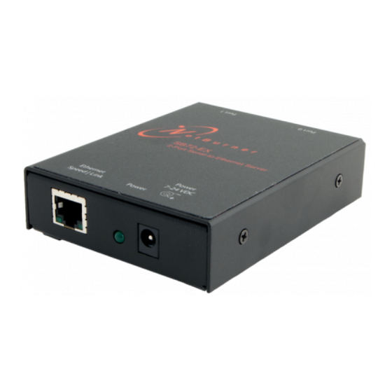
Page 15: Specifications
Power LED: Illuminated while power is applied. • LED1 on RJ-45: Ethernet speed - 10 or 100 • LED2 on RJ-45: Link and data activity Mechanical Dimensions: 4.1” x 3.125” x 1.0” SB72EX User's Manual, 350030-001 Page 15 Downloaded from Elcodis.com electronic components distributor... -
Page 16: Rs-232 Null Modem Wiring
The following table and diagram shows how to create a null modem cable/adapter for RS-232 connections. IMPORTANT: A null modem cable is required if you are connecting your SB72EX to a single computer. A standard serial cable will not work! -
Page 17: Testing With A Telnet Connection
One quick way to test the functionality of your Serial-to-Ethernet connection is with the Telnet program and an RS-232 Serial terminal program (e.g. MTTTY). Remember you must use a NULL modem able to connect your SB72EX to your host computer. To run this test, configure your system as one of the two examples shown below: The objective of this example is to use a single host computer running telnet and a serial terminal program to send data in either direction. - Page 18 Remove and reapply power to your SB72 EX. • The SB72EX factory application will boot. 5. Run Telnet by typing: “telnet 10.1.1.79 24” after the prompt, and press the Enter key. Note: This assumes a port number of 24. You must replace this port number with the listening port number that you assigned in the “Device Connection Settings (TCP mode)”...
Need help?
Do you have a question about the SB72EX and is the answer not in the manual?
Questions and answers