Table of Contents
Advertisement
Advertisement
Table of Contents

Related Manuals for Julabo SE-6


Summary of Contents for Julabo SE-6
- Page 1 English Operating Manual Heating Circulators HE-4 SE-6 SE-12 SE-26 Bridge Mounted Circulator SE-Z JULABO USA, Inc. 884 Marcon Boulevard Allentown, PA 18109 Phone: +1(610) 231-0250 Fax: +1(610) 231-0260 info.us@ julabo.com www.julabo.com 06/18 1.953.2442-V5 22.06.18...
- Page 2 Congratulations! You have made an excellent choice. JULABO thanks you for the trust you have placed in us. This operating manual has been designed to help you gain an understanding of the operation and possible applications of our circulators. For optimal utilization of all functions, we recommend that you thoroughly study this manual prior to beginning operation.
-
Page 3: Table Of Contents
HE / SE TABLE OF CONTENTS Operating manual ........................ 5 Intended use ......................... 5 1.1. Description ....................... 5 Operator responsibility – Safety recommendations ............6 2.1. Disposal ........................8 2.2. Technical specifications ................... 9 Operating instructions ....................... 11 Safety notes for the user ..................... 11 3.1. - Page 4 12.2. Communication with a PC or a superordinated data system ........70 12.3. List of commands ....................71 12.4. Status messages ....................74 12.5. Error messages .......................74 13. Installation of electronic module ...................75 14. JULABO Service – Online remote diagnosis ..............76 15. Cleaning / repairing the unit ..................77 16. WARRANTY PROVISIONS ..................78...
-
Page 5: Operating Manual
Operating manual Intended use JULABO circulators have been designed to control the temperature of specific fluids in a bath tank. The units feature pump connections for temperature control of external systems (loop circuit). JULABO circulators are not suitable for direct temperature control of foods, semi- luxury foods and tobacco, or pharmaceutical and medical products. -
Page 6: Operator Responsibility - Safety Recommendations
Operator responsibility – Safety recommendations Operator responsibility – Safety recommendations The products of JULABO ensure safe operation when installed, operated, and maintained according to common safety regulations. This section explains the potential dangers that may arise when operating the circulator and also specifies the most important safety precautions to preclude these dangers as far as possible. - Page 7 Warning label W26: Colors: yellow, black Hot surface warning. (The label is put on by JULABO) Observe the instructions in the manuals for instruments of a different make that you connect to the circulator, particularly the respective safety recommendations. Also observe the pin assignment of...
-
Page 8: Disposal
Operator responsibility – Safety recommendations 2.1. Disposal The circulator contains a back-up battery that supplies voltage to memory chips when the unit is switched off. Do not dispose of the battery with household waste! Depending on battery regulations in your country, you might be obliged to give back used or defect batteries to gathering places. -
Page 9: Technical Specifications
HE / SE 2.2. Technical specifications Heating circulators HE-4 SE-6 SE-12 SE-26 20 ... 300 20 ... 300 20 ... 300 20 … 250 Working temperature range °C ±0.01 ±0.01 ±0.01 ±0.01 Temperature stability °C 13x15 13x15 22x15 22x30 Bath opening (WxL) Bath depth 3 ... - Page 10 Operator responsibility – Safety recommendations Electrical connections: External alarm device 24-0 V DC / max. 25 mA Computer interface RS232 or RS485 External Pt100 sensor Optional for HE, SE (Order No. 8900100 Electronic module with analog connections) Programmer input -100 °C to 400 °C = 0 - 10 V or 0 - 20 mA or 4 - 20 mA Input for the signal of a flow meter or external manipulated variable Temperature recorder outputs 0 - 10 V (0 V = -100 °C, 10 V = 400 °C)
-
Page 11: Operating Instructions
HE / SE EMC requirements The device is an ISM device of group 1 per CISPR 11 (uses HF for internal purposes) and is classified in class A (industrial and commercial sector). Notice • Devices of class A are intended for the use in an industrial electromagnetic environment. •... -
Page 12: Safety Recommendations
Safety notes for the user 3.3. Safety recommendations Follow the safety instructions to avoid personal injury and property damage. Also, the valid safety instructions for workplaces must be followed. • Only connect the unit to a power socket with an earthing contact (PE – protective earth)! •... - Page 13 HE / SE Caution: The temperature controlling i.e. of fluids in a reactor constitutes normal circulator practice. We do not know which substances are contained within these vessels. Many substances are: • inflammable, easily ignited or explosive • hazardous to health •...
-
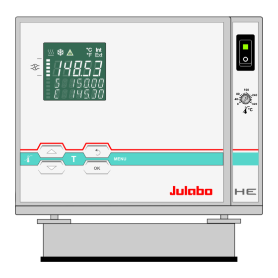
Page 14: Operating Controls And Functional Elements
Operating controls and functional elements Operating controls and functional elements Front view Rear view Mains power switch, illuminated VFD COMFORT-DISPLAY Header: Control indicators Line 1: Actual value internal or external The display is depending on the selected control mode in the menu >... - Page 15 HE / SE Control indicators in the header: Heating / Cooling / Alarm / emote control Control indicators in the header: Temperature indication Internal or External actual value Temperature indication in °C (°F not possible on this unit) Display of set pump pressure stage Four stages, can be set via the key , under >MENU - PUMP<.
- Page 16 Pt100 Interface RS232: remote control via personal computer SERIAL Socket: control cable of JULABO refrigerated circulator or output for alarm messages Option: Electronic module Order No. 8 900 100 Alarm output (for external alarm signal)
-
Page 17: Preparations
HE / SE Preparations 5.1. Installation Heating circulators • Place the unit on an even surface on a base made of nonflammable material. Bridge mounted circulator SE-Z • Place the bath tank in an upright position. 1. Remove screw on both sides (transportation safety device in the middle). -
Page 18: Bath Fluids
Fire or other dangers when using bath fluids that are not recommended: Please contact JULABO before using other than recommended bath fluids. Use only nonacidic and noncorrosive bath fluids. JULABO assumes no liability for damage caused by the selection of an unsuitable bath liquid. Unsuitable bath fluids are fluids which, e.g., •... -
Page 19: Temperature Application To External Systems
Differing flow rates of the pressure and suction pumps should be compensated. To maintain a constant liquid level, the JULABO „D+S“ Level Adapter is recommended for the external bath tank. The flow rate of the pressure pump will be then regulated by a built-in float device. -
Page 20: Tubing
Preparations Return flow safety device If the liquid levels in the circulator bath and the external system are at different heights, overflowing must be prevented after the power has been turned off. Flood hazard! For this reason, shut-off valves can be integrated in the loop circuit. Order No. -
Page 21: Filling / Draining
HE / SE 5.4. Filling / draining Notice: • Pay attention to the thermal expansion of bath oil during heating to avoid overflowing of the liquid. • Do not drain the bath fluid while it is hot! Recommendation: Temperature range 5 °C to 40 °C Check the temperature of the bath fluid prior to draining (by switching the unit on for a short moment, for example). -
Page 22: Countercooling
Preparations 5.5. Countercooling Caution: Securely attach all tubing to prevent slipping. Observe the laws and regulations of the water distribution company valid in the location where the unit is operated. For applications near the ambient temperature, the cooling coil (20) must be connected to the water mains. SERIAL ALARM STAND-BY... -
Page 23: Operating Procedures
HE / SE Operating procedures 6.1. Power connection Caution: • Only connect the unit to a power socket with earthing contact (PE – protective earth)! • The power supply plug serves as safe disconnecting device from the line and must be always easily accessible. -
Page 24: Setting Of Temperatures
Setting of temperatures Setting of temperatures 7.1. Using the pre-settings in the menu Press the key to call up the menu for temperature selection. 3 different working temperatures can be adjusted. Their values are freely selectable within the operating temperature range. ... -
Page 25: Direct Setting Of Temperatures
HE / SE 7.2. Direct setting of temperatures The circulator uses the setpoint of SETPNT 1 or 2 or 3 for temperature control The indicated setpoint temperature can be changed directly any time. Example: change 25.00 °C to 50.00 °C 1. -
Page 26: Safety Installations, Warning Functions
Safety installations, warning functions Safety installations, warning functions Check the safety installations at least twice a year! Refer to ( page 13) SECVAL Settings for the excess temperature protection > SAFETMP< (Security Values) and for the warning functions for high > OVERTMP< and low > ... -
Page 27: Early Warning System, Low Level Protection
HE / SE 8.1.1. Early warning system, low level protection This low level protection is independent of the control circuit and is divided into two sections: . 1. Switch in stage 1 recognizes a defined fluid level An audible warning sounds (interval tone) and together with the ticker: >... -
Page 28: Switch-Over From Warning To Shutdown Function
Safety installations, warning functions 8.2. Switch-over from warning to shutdown function If a shutdown of functional elements (e.g. heater, circulating pump) is required when the limit values are exceeded or undercut the circulator can be changed over from warning function >WARNING< to shutdown function >ALARM<. -
Page 29: Over And Sub Temperature Warning Function
HE / SE 8.3. Over and Sub temperature warning function If the observance of a working temperature value >SETP< has to be supervised for a sensitive temperature application, then set over and sub Over temperature temperature warning values. In the example below the SETPOINT 85 °C is surrounded by the values OVERTMP 87 °C and SUBTEMP 83 °C. -
Page 30: Menu Functions
Menu functions Menu functions 1. Open the menu by pressing the key. 2. Use the keys to scroll in menu level 1. 3. Press the key to change to menu level 2. Press the key if settings are to be retained. The term „Menu functions“... -
Page 31: Menu Program - Start
HE / SE Menu level 1 Analog inputs/outputs Page 57 Recorder output – CHANNEL 1, 2, 3 EPROG – External programmer input EX-STBY - STAND-BY input ALARM - output 9.1. MENU PROGRAM – START This menu will start a previously set program. ... - Page 32 Menu functions Level 2 Parameter level • Confirm >NOW< with the key and the program will start immediately start at the set time under parameter (TIMER ). Set time in the example below: 09. August 2009, 11:15 hrs ...
- Page 33 HE / SE The started program After the start the program will indicate the currently calculated setpoint in line S XX.XX. The value increases within the time period >TSLICE< until the target temperature >SETPNT< of the section is reached. If the time period in a section is set to „0“, the next section will not begin until the target temperature has been reached.
-
Page 34: Menu Program - Creation, Administration
Menu functions 9.2. MENU PROGRAM – creation, administration The integrated programmer permits fast and easy programming of setpoint Menu level 1 temperature sequences. This temperature sequence is called program. A program is composed of individual sections (STEP). The sections are defined by duration (TSLICE) and target temperature. - Page 35 HE / SE Menu level 1 >EDIT< Create, administer program > STEP< Program step (1 ... 10) >SETPNT < Temperature setpoint of step ... >TSLICE< Duration of step ... > DELETE< delete program step (01 … 10, ALL) Press key, if a parameter is to be retained.
-
Page 36: Menu Pump - Setting Of Pump Pressure
Menu functions 9.3. MENU PUMP - Setting of pump pressure The pressure of the circulating pump is adjustable in four stages. After setting, the VFD COMFORT-DISPLAY indicates the corresponding value. Adjustable pump capacity stage 1 ... 4 Examples: Illuminated display: for pump pressure Soll ... -
Page 37: Menu Config - Configuration Of Unit
HE / SE 9.4. MENU CONFIG - Configuration of unit Menu level 1 A RESET can be effected only in the >OFF< mode. Switch off circulator by pressing the key and call up the menu CONFIGURATION. Level 2 Parameter level ... -
Page 38: Remote Control Via The Serial Interface
Menu functions Level 2 Level 3 Parameter level • Hours flash, set by pressing • Minutes flash, set by pressing • Day flashes, set by pressing • Month flashes, set by pressing • Year flashes, set by pressing •... -
Page 39: Keypad Control Or Setpoint Setting Via The Analog Input
Take care to fully observe the safety and warning functions of the circulator. Notice: Factory settings: OFF The circulator has been configured and delivered by JULABO in accordance with the NAMUR recommendations. This means for the start mode that the unit must enter a safe operating status after a power failure. -
Page 40: Off-Mode
Menu functions 9.4.4. OFF-MODE Usually the circulating pump is controlled with the key or the Factory setting: start/stop command. If the circulating pump is to work in the –OFF- PMP OFF mode, the adjustment can be set in a sub-menu. ... -
Page 41: Setting Of Clock And Date
HE / SE 9.4.6. Setting of clock and date The internal real time clock allows starting a program any time. The clock is set to the local mean time (MEZ) at the factory. If the unit is operated in a different time zone, the clock can be adjusted in this menu. - Page 42 Menu functions Level 2 Parameter level C-TYPE INTERNAL • The parameter flashes, switch by pressing This parameter affects the temperature sequence in case of internal control. • The parameter flashes, set by pressing 0.1 … 99.9 • The parameter flashes, set by pressing ...
-
Page 43: Control - Control Internal / External
HE / SE 9.5.1. CONTROL – Control INTERNAL / EXTERNAL Switchover can only be effected if a Pt100 external sensor is connected. Pt100 Factory setting: INT IMPORTANT: Additional measures for external temperature control Suggested settings for external temperature control: BAND HIGH / LOW and INTERN MAX / MIN see chapter >MENU LIMITS<. -
Page 44: Selftuning
Menu functions 9.5.2. SELFTUNING Selftuning: When performing a selftuning for the controlled system (temperature application system), the control parameters Xp, Tn and Tv are automatically determined and stored. Possible parameters: OFF - no selftuning The control parameters ascertained during the last identification are used for control purposes. -
Page 45: Control Parameters- Xp-, Tn-, Tv- Internal
HE / SE 9.5.4. Control parameters– XP-, TN-, TV- INTERNAL In most cases the control parameters preset in the factory are adequate for achieving an optimum temperature sequence. The control parameters allow adjustment to special control processes.. Proportional range >Xp< The proportional range is the range below the setpoint in which the control circuit reduces the heating capacity from 100% to 0 % Setting range: 0.1 ... -
Page 46: Cospeed - External
Menu functions 9.5.5. COSPEED - external This parameter affects the temperature pattern only in case of external control. Possible parameters: 0.0 ... 5.0 During selftuning, the control parameters Xp, Tn and Tv of a controlled system are automatically determined and stored. Depending on the controlled system, time for tuning can be unequally longer. -
Page 47: Menu Serial - Baudrate, Handshake, Parity
HE / SE 9.6. MENU SERIAL - BAUDRATE, HANDSHAKE, PARITY Menu level 1 For communication between circulator and a PC or a superordinated process control system the interface parameters of both units must be identical. For remote control refer to page 70 Factory settings: 4800 Baud ... -
Page 48: Menu Atc - Absolut Temperature Calibration
Menu functions 9.7. MENU ATC - Absolut Temperature Calibration ATC serves to compensate a temperature difference that might occur between circulator and a defined measuring point in the bath tank because of physical properties. Principle: For ATC calibration, in steady state the bath temperature at the location Example: of the temperature sensor (CT) is determined at the respective adjusted 1-point calibration... - Page 49 HE / SE Menu level 1 Press the key if parameter is to be retained. Level 2 Parameter level Correction function for parameters or values (prior to OK). • The parameter flashes, switch by pressing On level 2 a (I) is indicated for internal or an (E) for external.
-
Page 50: Atc Sensor - Internal / External
Menu functions Level 2 Parameter level • Integer digits flash, set by pressing • Decimal digits flash, set by pressing If only a 2-point calibration is carried out, the following menu items are not indicated anymore The value is only indicated ... -
Page 51: Calibration Type: 1 -/ 2 -/ 3 Point
HE / SE 9.7.3. CALIBRATION TYPE: 1 -/ 2 -/ 3 POINT A >1-point<, >2-point< or >3-point< calibration can be carried out. First geometrically define the location for calibration (measuring point CT), then determine the temperature values of the calibration points. The type of calibrations also determines the number of the following pairs of values indicated on the LCD DIALOG-DISPLAY. -
Page 52: Example: 3-Point Calibration For Internal Control
Menu functions 9.7.4. Example: 3-point calibration for internal control In the temperature range from 80 °C to 160 °C the calibration curve of the temperature sensor (TT) is to be adjusted to the actual temperatures at measuring point (CT). 1. Set circulator to internal control: MENU CONTROL page 41 Menu level 1 The type of control can be set only in the –OFF- mode. - Page 53 HE / SE • The parameter flashes, switch by pressing A >3-point< calibration is carried out. The value >TMPVAL< is only indicated In addition the measured value >CALVAL X< is saved during the following step • Integer digits flash, set by pressing (79) + ...
-
Page 54: Menu Limits - Begrenzungen
Menu functions 9.8. MENU LIMITS - Begrenzungen Menu level 1 Level 2 Parameter level Press the key if parameter is to be retained. Correction function for parameters or values (prior to OK). • Integer digits flash, set by pressing ... -
Page 55: Limits For Internal Control
HE / SE 9.8.1. Limits for internal control SETPOINT MAX / MIN – Maximum and minimum setpoint Restriction of the adjustable temperature range. The limitation of the operating temperature range effects the temperature setting in the menu with the key Only setting of working temperatures which lie within the determined limits is possible Existing settings for SETPNT 1, -2, -3, as well as those for >OVERTMP<... - Page 56 Menu functions BAND HIGH / LOW – Band limitation The band limitation is active during external control. Varied, practice- oriented setting are feasible for heat-up and cool-down phases. Setting range: 0 °C ... 200 °C BAND HIGH and BAND LOW allow for the limitation of the difference between the temperatures in the internal bath and the external system to any maximum value for the heat-up and cool-down phase.
-
Page 57: Menu In/Out - Analog Inputs/Outputs (Option)
HE / SE 9.9. MENU IN/OUT – Analog inputs/outputs (Option) In order to use the analog inputs and outputs, the circulator must be equipped with the electronic module available as option. Order No. 8 900 100 Electronic module ALARM STAND-BY REG+ This submenu enables setting of the input and output values for the... - Page 58 Menu functions Level 2 Level 3 Parameter level • Integer digits flash, set by pressing • Decimal digits flash, set by pressing • The parameter flashes, switch by pressing • Integer digits flash, set by pressing ...
- Page 59 HE / SE Level 2 Level 3 Parameter level • Integer digits flash, set by pressing Lower VALue • Decimal digits flash, set by pressing Upper VALue • The parameter flashes, switch by pressing • The parameter flashes, switch by pressing ...
-
Page 60: Outputs Of The Connector - Reg+E-Prog
Menu functions 9.9.1. Outputs of the connector - REG+E-PROG REG+E-PROG : CHANNEL 3 EPROG Select CHANNEL 1, 2 or 3 CHANNEL 2 First define the desired output value for CHANNELs 1 to 3: CHANNEL 1 internal actual temperature value (bath temperature)) REG+E-PROG external actual temperature value (external sensor) periodic or intermittent heating or cooling... -
Page 61: Input Of The Connector - Reg+E-Prog
HE / SE 9.9.2. Input of the connector - REG+E-PROG CHANNEL 3 Setting needs to be carried out, if EPROG setpoint programming is to be made via an external voltage or CHANNEL 2 current source or programmer. For this, in the menu > MENU / CONFIG < first set CHANNEL 1 the menu item >... - Page 62 Menu functions Examples – Setting the LOW value: (See below First adjust and set the lowest voltage or current on the external voltage or current source (e.g. 0 V or 0 mA). Then after approx. 30 secs enter the corresponding temperature value (e.g.
-
Page 63: Alarm-Output / Stand-By-Input
HE / SE Example out of diagram A: • Adjusting the voltage source for an output of 7.6 V! The instrument calculates this value from the rise angle of the two predecided end points (in example A: 7.6 V correspond to an external setpoint temperature of 152.0 °C ). - Page 64 Menu functions EX-STBY: External Stand-by input (for external switch-off) Possible parameters: INACTIV - standby input is ignored ACTIV - standby input is active Activate the standby input: STAND-BY 1. Under menu item > EXT-STBY <, set the parameter to >ACTIV<. 2.
-
Page 65: 10. Troubleshooting Guide / Error Messages
Replace the tubing and refill bath liquid. The float is defect (e.g. transport damage). Repair by authorized JULABO service personnel. Error message with ticker: > REFRIGERATOR ALARM-CHECK CONNECTION < During the self-test after switch-on a short –circuit is detected between pin 2 and pin 4 of the control line or the control line was disconnected during operation. - Page 66 > CONFIGURATION ERROR-PRESS OK< The configuration of the circulator does not correspond with its current application. Press the key for a non-recurring, automatic change of the configuration. In this case please call the JULABO Technical Service or an authorized dealer.
- Page 67 HE / SE Disturbances that are not indicated. The electronic pump motor is overload-protected by an electronic current limiter. If viscosity of the bath fluid is or becomes too high, the motor stops running. Warning: Before exchanging the fuses, turn off the mains power switch and disconnect the power plug from the mains socket! Only use fine fuses with a nominal value as specified.
-
Page 68: 11. Electrical Connections
Electrical connections 11. Electrical connections Notice: Use shielded cables only. The shield of the connecting cable is electrically connected to the plug housing. The unit ensures safe operation if connecting cables with a maximum length of 3 m are used. The use of longer cables does not affect proper performance of the unit, however external interferences may have a negative impact on safe operation (e.g. - Page 69 HE / SE / Control output The connector may only be used for control of a JULABO refrigerated circulator or JULABO MVS Solenoid valve controller for cooling water. Pin assignment: Signal (only with attached JULABO equipment) +24 V (I max. current 25 mA)
-
Page 70: 12. Remote Control
Remote control 12. Remote control 12.1. Setup for remote control 1. Check the interface parameters for both interfaces (on circulator and PC) and make sure they match. (Serial interface refer to page 47) RS232C 2. In the menu > MENU CONFIG < set the menu item 3. -
Page 71: List Of Commands
HE / SE 12.3. List of commands OUT commands: Setting temperature values or parameters. Command Parameter Response of circulator OUT_MODE_01 Use working temperature > SETPNT 1< OUT_MODE_01 Use working temperature > SETPNT 2< OUT_MODE_01 Use working temperature > SETPNT 3< OUT_MODE_02 Selftuning „off“. - Page 72 Remote control Command Parameter Response of circulator OUT_PAR_12 Tv control parameter of the cascade controller. 0 ... 999 OUT_PAR_13 Maximum internal temperature of the cascade controller. OUT_PAR_14 Minimum internal temperature of the cascade controller. OUT_PAR_15 Band limit (upper) 0 ... 200 °C OUT_PAR_16 Band limit (lower) 0 ...
- Page 73 HE / SE Command Parameter Response of circulator IN_PAR_04 none CoSpeed - Band limit (max. difference between the temperatures in the internal bath and external system). IN_PAR_05 none Factor pk/ph0: Ratio of max. cooling capacity versus max. heating capacity IN_PAR_06 none Xp control parameter of the internal controller.
-
Page 74: Status Messages
Remote control 12.4. Status messages Status messages Description 00 MANUAL STOP Circulator in „OFF“ state. 01 MANUAL START Circulator in keypad control mode. 02 REMOTE STOP Circulator in „r OFF“ state. 03 REMOTE START Circulator in remote control mode. 12.5. Error messages Error messages Description... -
Page 75: 13. Installation Of Electronic Module
HE / SE Error messages Description -23 WARNING: HIGH TEMPERATURE Excess temperature on compressor stage 1. ON COMPRESSOR STAGE 1 -24 WARNING: HIGH TEMPERATURE Excess temperature on compressor stage 2. ON COMPRESSOR STAGE 2 -25 REFRIGERATOR WARNING Error in the cooling machine. -26 WARNING: STAND-BY PLUG IS External standby contact is open. -
Page 76: 14. Julabo Service - Online Remote Diagnosis
JULABO Service – Online remote diagnosis 14. JULABO Service – Online remote diagnosis JULABO circulators of the HighTech series are equipped with a black box. This box is implemented in the controller and records all significant data for the last 30 minutes. -
Page 77: 15. Cleaning / Repairing The Unit
The circulator is designed for continuous operation under normal conditions. Periodic maintenance is not required. The tank should be filled only with a bath fluid recommended by JULABO. To avoid contamination, it is essential to change the bath fluid from time to time. Repairs... -
Page 78: 16. Warranty Provisions
WARRANTY PROVISIONS 16. WARRANTY PROVISIONS The following Warranty Provisions shall apply to products sold in North America by Julabo (“Seller”) to the entity shown as buyer (“Buyer”) on Seller’s invoice. Initial Warranty. Upon Seller’s receipt of payment in full for the products and subject to Buyer’s... - Page 79 HE / SE INCIDENTAL OR CONSEQUENTIAL DAMAGES TO BUYER OR ANY THIRD PARTY AND ALL SUCH DAMAGES ARE HEREBY DISCLAIMED. Assignment. Buyer shall not assign any of its rights or obligations hereunder without the prior written approval of Seller; provided, however, that if Buyer is a distributor of Seller, the rights and obligations of Buyer under these Warranty Provisions shall inure to the benefit of and be binding upon Buyer’s customers who provide the product’s proof of purchase to Seller pursuant to the terms set forth herein.
Need help?
Do you have a question about the SE-6 and is the answer not in the manual?
Questions and answers