Kaya Instruments JetCam User Manual
Hide thumbs
Also See for JetCam:
- Quick start manual (15 pages) ,
- Quick troubleshooting manual (9 pages) ,
- Manual (10 pages)
Table of Contents
Advertisement
Quick Links
International Distributors
JetCam
User Manual
December 2020
Sky Blue Microsystems GmbH
Geisenhausenerstr. 18
81379 Munich, Germany
+49 89 780 2970, info@skyblue.de
www.skyblue.de
-
Rev 1.0
In Great Britain:
Zerif Technologies Ltd.
Winnington House, 2 Woodberry Grove
Finchley, London N12 0DR
+44 115 855 7883, info@zerif.co.uk
www.zerif.co.uk
Advertisement
Table of Contents

Related Manuals for Kaya Instruments JetCam


Summary of Contents for Kaya Instruments JetCam
- Page 1 JetCam User Manual December 2020 Rev 1.0 International Distributors In Great Britain: Sky Blue Microsystems GmbH Zerif Technologies Ltd. Winnington House, 2 Woodberry Grove Geisenhausenerstr. 18 81379 Munich, Germany Finchley, London N12 0DR +49 89 780 2970, info@skyblue.de +44 115 855 7883, info@zerif.co.uk www.skyblue.de...
-
Page 2: Table Of Contents
2 0 H a M e s i l a S t . , N e s h e r 3 6 8 8 5 2 0 , I s r a e l P O B 2 5 0 0 4 , H a i f a 3 1 2 5 0 0 1 , I s r a e l T e l : ( + 9 7 2 ) - 7 2 - 2 7 2 3 5 0 0 F a x : ( + 9 7 2 ) - 7 2 - 2 7 2 3 5 1 1 Table of Contents... - Page 3 7.10 Test Control.............................41 7.10.1 Test Control XML Parameters ......................41 7.10.2 Build-In-Test ............................43 CLI Interface ..............................44 JetCam Terminal control .........................44 JetCam Firmware update ........................44 Optional peripheral add-ons ........................47 Appendix .................................50 Lens Mount Installation Manual ......................50 10 Troubleshooting ..............................52 10.1 The camera is connected but the LED are not lit ..................52 10.2...
-
Page 4: Figures & Tables
Figure 44 – Birger GUI setup 1 ..........................48 Figure 45 – Birger GUI setup 2 ..........................49 Figure 46 – JetCam front panel and the lens mount ....................50 Figure 47 – Positioning the mount over the front panel ..................50 Figure 48 – Carefully handle the screws to avoid scratches ...................50 www.kayainstruments.com... -
Page 5: List Of Tables
2 0 H a M e s i l a S t . , N e s h e r 3 6 8 8 5 2 0 , I s r a e l P O B 2 5 0 0 4 , H a i f a 3 1 2 5 0 0 1 , I s r a e l T e l : ( + 9 7 2 ) - 7 2 - 2 7 2 3 5 0 0 F a x : ( + 9 7 2 ) - 7 2 - 2 7 2 3 5 1 1 Figure 49 –... -
Page 6: Revision History
2 0 H a M e s i l a S t . , N e s h e r 3 6 8 8 5 2 0 , I s r a e l P O B 2 5 0 0 4 , H a i f a 3 1 2 5 0 0 1 , I s r a e l T e l : ( + 9 7 2 ) - 7 2 - 2 7 2 3 5 0 0 F a x : ( + 9 7 2 ) - 7 2 - 2 7 2 3 5 1 1 2 Revision History... -
Page 7: Introduction
3 Introduction 3.1 Safety Precautions With your JetCam camera in hand, please take the time to read the precautions listed below in order to prevent preventable and unnecessary injuries and damage to you, other personnel or property. Read these safety instructions carefully prior to your first use of the product, as these precautions contain safety instructions that must be observed. -
Page 8: Disclaimer
T e l : ( + 9 7 2 ) - 7 2 - 2 7 2 3 5 0 0 F a x : ( + 9 7 2 ) - 7 2 - 2 7 2 3 5 1 1 3.2 Disclaimer This product should only be used for image capturing and processing. KAYA Instruments will assume no responsibility for any damage that may ensue by the use of the camera for any purpose other than intended, as previously stated. -
Page 9: Overview
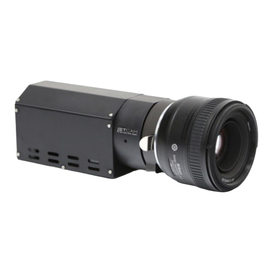
4 Overview This document provides an extensive overview of KAYS’s JetCam camera line-up, currently consisting of the JetCam 19 and JetCam 160. All cameras are suited for a wide variety of applications, high-speed and high-quality image streaming and with 3G-SDI output. -
Page 10: Mechanical Properties
T e l : ( + 9 7 2 ) - 7 2 - 2 7 2 3 5 0 0 F a x : ( + 9 7 2 ) - 7 2 - 2 7 2 3 5 1 1 5 Mechanical Properties This section provides information on JetCam camera unit hardware. It covers architecture, interfaces and pin assignments for various connectors. -
Page 11: System Status Led
Table 4 – System status indicating lamp states 5.3 Power Connector The JetCam unit requires 12V power supply for proper function. Please, refer to section 6 for exact Power Supply requirements. The positive pin of the power supply connected to the bottom pin of the connector, shown as “12V”, the negative pin connected to the upper right pin of the connector, shown as “GND“. -
Page 12: Gpio Connector
2 0 H a M e s i l a S t . , N e s h e r 3 6 8 8 5 2 0 , I s r a e l P O B 2 5 0 0 4 , H a i f a 3 1 2 5 0 0 1 , I s r a e l T e l : ( + 9 7 2 ) - 7 2 - 2 7 2 3 5 0 0 F a x : ( + 9 7 2 ) - 7 2 - 2 7 2 3 5 1 1 5.6 GPIO connector... -
Page 13: Connecting The Interface Cable To Qsfp+ Module
Figure 4 – Connecting the QSFP+ cable 5.7.3 Removing the QSFP+ Module 1. Turn the JetCam camera off. 2. Disconnect and remove all interface cables from the ports. 3. Hold the pull-tab latch on the QSFP+ module with your index finger, and gently pull to release the transceiver from the socket. -
Page 14: Dual Sfp+ Installation
2. The SFP+ module has a bale clasp that used to remove or install the SFP+ module. 3. Close the bale clasp before inserting the SFP+ module into the JetCam camera. 4. Line up the module with the port and slide it into the port. -
Page 15: Connecting The Interface Cable To Sfp+ Module
Both the TX and RX fiber cables must be connected between TX output (Marked with TX or Arrow outwards the SFP+) on the JetCam camera and RX input (Marked with RX or Arrow inwards the SFP+) on your Frame Grabber device. -
Page 16: Color Filter Array
5.9 Color Filter Array The JetCam 19 and JetCam 261 color sensors processed with a Bayer RGB color pattern as shown in Figure 11. The Bayer type is GBRG: Pixel (0, 0) has a green filter and in the same row there is a blue filter. On the other row there is a red filter and another green filter next to it. -
Page 17: Mechanical Dimensions
2 0 H a M e s i l a S t . , N e s h e r 3 6 8 8 5 2 0 , I s r a e l P O B 2 5 0 0 4 , H a i f a 3 1 2 5 0 0 1 , I s r a e l T e l : ( + 9 7 2 ) - 7 2 - 2 7 2 3 5 0 0 F a x : ( + 9 7 2 ) - 7 2 - 2 7 2 3 5 1 1 5.10 Mechanical dimensions... -
Page 18: Electrical Properties
2 0 H a M e s i l a S t . , N e s h e r 3 6 8 8 5 2 0 , I s r a e l P O B 2 5 0 0 4 , H a i f a 3 1 2 5 0 0 1 , I s r a e l T e l : ( + 9 7 2 ) - 7 2 - 2 7 2 3 5 0 0 F a x : ( + 9 7 2 ) - 7 2 - 2 7 2 3 5 1 1 6 Electrical Properties... -
Page 19: Configuration Interface
2 0 H a M e s i l a S t . , N e s h e r 3 6 8 8 5 2 0 , I s r a e l P O B 2 5 0 0 4 , H a i f a 3 1 2 5 0 0 1 , I s r a e l T e l : ( + 9 7 2 ) - 7 2 - 2 7 2 3 5 0 0 F a x : ( + 9 7 2 ) - 7 2 - 2 7 2 3 5 1 1 7 Configuration Interface... - Page 20 2 0 H a M e s i l a S t . , N e s h e r 3 6 8 8 5 2 0 , I s r a e l P O B 2 5 0 0 4 , H a i f a 3 1 2 5 0 0 1 , I s r a e l T e l : ( + 9 7 2 ) - 7 2 - 2 7 2 3 5 0 0 F a x : ( + 9 7 2 ) - 7 2 - 2 7 2 3 5 1 1 Processor...
-
Page 21: Image Format Control
2 0 H a M e s i l a S t . , N e s h e r 3 6 8 8 5 2 0 , I s r a e l P O B 2 5 0 0 4 , H a i f a 3 1 2 5 0 0 1 , I s r a e l T e l : ( + 9 7 2 ) - 7 2 - 2 7 2 3 5 0 0 F a x : ( + 9 7 2 ) - 7 2 - 2 7 2 3 5 1 1 7.2 Image Format Control... - Page 22 2 0 H a M e s i l a S t . , N e s h e r 3 6 8 8 5 2 0 , I s r a e l P O B 2 5 0 0 4 , H a i f a 3 1 2 5 0 0 1 , I s r a e l T e l : ( + 9 7 2 ) - 7 2 - 2 7 2 3 5 0 0 F a x : ( + 9 7 2 ) - 7 2 - 2 7 2 3 5 1 1 0x00000332...
-
Page 23: Acquisition Control
2 0 H a M e s i l a S t . , N e s h e r 3 6 8 8 5 2 0 , I s r a e l P O B 2 5 0 0 4 , H a i f a 3 1 2 5 0 0 1 , I s r a e l T e l : ( + 9 7 2 ) - 7 2 - 2 7 2 3 5 0 0 F a x : ( + 9 7 2 ) - 7 2 - 2 7 2 3 5 1 1 7.3 Acquisition Control... -
Page 24: Exposure Time
2 0 H a M e s i l a S t . , N e s h e r 3 6 8 8 5 2 0 , I s r a e l P O B 2 5 0 0 4 , H a i f a 3 1 2 5 0 0 1 , I s r a e l T e l : ( + 9 7 2 ) - 7 2 - 2 7 2 3 5 0 0 F a x : ( + 9 7 2 ) - 7 2 - 2 7 2 3 5 1 1 Exposure Time... - Page 25 2 0 H a M e s i l a S t . , N e s h e r 3 6 8 8 5 2 0 , I s r a e l P O B 2 5 0 0 4 , H a i f a 3 1 2 5 0 0 1 , I s r a e l T e l : ( + 9 7 2 ) - 7 2 - 2 7 2 3 5 0 0 F a x : ( + 9 7 2 ) - 7 2 - 2 7 2 3 5 1 1 Steps to set Auto Exposure Mode:...
- Page 26 2 0 H a M e s i l a S t . , N e s h e r 3 6 8 8 5 2 0 , I s r a e l P O B 2 5 0 0 4 , H a i f a 3 1 2 5 0 0 1 , I s r a e l T e l : ( + 9 7 2 ) - 7 2 - 2 7 2 3 5 0 0 F a x : ( + 9 7 2 ) - 7 2 - 2 7 2 3 5 1 1 The next table specifies the Auto Exposure parameters:...
-
Page 27: Combined Auto Exposure & Auto Gain Mode
2 0 H a M e s i l a S t . , N e s h e r 3 6 8 8 5 2 0 , I s r a e l P O B 2 5 0 0 4 , H a i f a 3 1 2 5 0 0 1 , I s r a e l T e l : ( + 9 7 2 ) - 7 2 - 2 7 2 3 5 0 0 F a x : ( + 9 7 2 ) - 7 2 - 2 7 2 3 5 1 1 3. - Page 28 2 0 H a M e s i l a S t . , N e s h e r 3 6 8 8 5 2 0 , I s r a e l P O B 2 5 0 0 4 , H a i f a 3 1 2 5 0 0 1 , I s r a e l T e l : ( + 9 7 2 ) - 7 2 - 2 7 2 3 5 0 0 F a x : ( + 9 7 2 ) - 7 2 - 2 7 2 3 5 1 1 The average value is calculated by the following formulas:...
-
Page 29: Auto Exposure & Gain Roi Definition
2 0 H a M e s i l a S t . , N e s h e r 3 6 8 8 5 2 0 , I s r a e l P O B 2 5 0 0 4 , H a i f a 3 1 2 5 0 0 1 , I s r a e l T e l : ( + 9 7 2 ) - 7 2 - 2 7 2 3 5 0 0 F a x : ( + 9 7 2 ) - 7 2 - 2 7 2 3 5 1 1 7.3.6 Auto Exposure &... -
Page 30: Analog Control
2 0 H a M e s i l a S t . , N e s h e r 3 6 8 8 5 2 0 , I s r a e l P O B 2 5 0 0 4 , H a i f a 3 1 2 5 0 0 1 , I s r a e l T e l : ( + 9 7 2 ) - 7 2 - 2 7 2 3 5 0 0 F a x : ( + 9 7 2 ) - 7 2 - 2 7 2 3 5 1 1 7.4 Analog Control... -
Page 31: White Balance Xml Parameters
2 0 H a M e s i l a S t . , N e s h e r 3 6 8 8 5 2 0 , I s r a e l P O B 2 5 0 0 4 , H a i f a 3 1 2 5 0 0 1 , I s r a e l T e l : ( + 9 7 2 ) - 7 2 - 2 7 2 3 5 0 0 F a x : ( + 9 7 2 ) - 7 2 - 2 7 2 3 5 1 1 Auto Gain Min... -
Page 32: Isp Features
2 0 H a M e s i l a S t . , N e s h e r 3 6 8 8 5 2 0 , I s r a e l P O B 2 5 0 0 4 , H a i f a 3 1 2 5 0 0 1 , I s r a e l T e l : ( + 9 7 2 ) - 7 2 - 2 7 2 3 5 0 0 F a x : ( + 9 7 2 ) - 7 2 - 2 7 2 3 5 1 1 Balance White... -
Page 33: Lut Control
2 0 H a M e s i l a S t . , N e s h e r 3 6 8 8 5 2 0 , I s r a e l P O B 2 5 0 0 4 , H a i f a 3 1 2 5 0 0 1 , I s r a e l T e l : ( + 9 7 2 ) - 7 2 - 2 7 2 3 5 0 0 F a x : ( + 9 7 2 ) - 7 2 - 2 7 2 3 5 1 1 7.6 LUT control... -
Page 34: Pixel Correction Control
2 0 H a M e s i l a S t . , N e s h e r 3 6 8 8 5 2 0 , I s r a e l P O B 2 5 0 0 4 , H a i f a 3 1 2 5 0 0 1 , I s r a e l T e l : ( + 9 7 2 ) - 7 2 - 2 7 2 3 5 0 0 F a x : ( + 9 7 2 ) - 7 2 - 2 7 2 3 5 1 1 7.7 Pixel Correction Control... -
Page 35: Defect Pixel Correction
2 0 H a M e s i l a S t . , N e s h e r 3 6 8 8 5 2 0 , I s r a e l P O B 2 5 0 0 4 , H a i f a 3 1 2 5 0 0 1 , I s r a e l T e l : ( + 9 7 2 ) - 7 2 - 2 7 2 3 5 0 0 F a x : ( + 9 7 2 ) - 7 2 - 2 7 2 3 5 1 1 7.7.2 Defect Pixel Correction... - Page 36 2 0 H a M e s i l a S t . , N e s h e r 3 6 8 8 5 2 0 , I s r a e l P O B 2 5 0 0 4 , H a i f a 3 1 2 5 0 0 1 , I s r a e l T e l : ( + 9 7 2 ) - 7 2 - 2 7 2 3 5 0 0 F a x : ( + 9 7 2 ) - 7 2 - 2 7 2 3 5 1 1 Where P(x,y) is the pixel at offset X in horizontal and Y in vertical.
- Page 37 2 0 H a M e s i l a S t . , N e s h e r 3 6 8 8 5 2 0 , I s r a e l P O B 2 5 0 0 4 , H a i f a 3 1 2 5 0 0 1 , I s r a e l T e l : ( + 9 7 2 ) - 7 2 - 2 7 2 3 5 0 0 F a x : ( + 9 7 2 ) - 7 2 - 2 7 2 3 5 1 1 There might be limits to the total difference that you will be able to correct for.
-
Page 38: Lens Control
2 0 H a M e s i l a S t . , N e s h e r 3 6 8 8 5 2 0 , I s r a e l P O B 2 5 0 0 4 , H a i f a 3 1 2 5 0 0 1 , I s r a e l T e l : ( + 9 7 2 ) - 7 2 - 2 7 2 3 5 0 0 F a x : ( + 9 7 2 ) - 7 2 - 2 7 2 3 5 1 1 7.8 Lens Control... -
Page 39: Lens Control Parameters
2 0 H a M e s i l a S t . , N e s h e r 3 6 8 8 5 2 0 , I s r a e l P O B 2 5 0 0 4 , H a i f a 3 1 2 5 0 0 1 , I s r a e l T e l : ( + 9 7 2 ) - 7 2 - 2 7 2 3 5 0 0 F a x : ( + 9 7 2 ) - 7 2 - 2 7 2 3 5 1 1 7.8.1 Lens Control Parameters... - Page 40 2 0 H a M e s i l a S t . , N e s h e r 3 6 8 8 5 2 0 , I s r a e l P O B 2 5 0 0 4 , H a i f a 3 1 2 5 0 0 1 , I s r a e l T e l : ( + 9 7 2 ) - 7 2 - 2 7 2 3 5 0 0 F a x : ( + 9 7 2 ) - 7 2 - 2 7 2 3 5 1 1 Gen<i>Cam Category: LensIrisControl...
-
Page 41: User Set Control
2 0 H a M e s i l a S t . , N e s h e r 3 6 8 8 5 2 0 , I s r a e l P O B 2 5 0 0 4 , H a i f a 3 1 2 5 0 0 1 , I s r a e l T e l : ( + 9 7 2 ) - 7 2 - 2 7 2 3 5 0 0 F a x : ( + 9 7 2 ) - 7 2 - 2 7 2 3 5 1 1 7.9 User Set Control... -
Page 42: Userset Operation Sequence
2 0 H a M e s i l a S t . , N e s h e r 3 6 8 8 5 2 0 , I s r a e l P O B 2 5 0 0 4 , H a i f a 3 1 2 5 0 0 1 , I s r a e l T e l : ( + 9 7 2 ) - 7 2 - 2 7 2 3 5 0 0 F a x : ( + 9 7 2 ) - 7 2 - 2 7 2 3 5 1 1 7.9.2 UserSet operation sequence... - Page 43 2 0 H a M e s i l a S t . , N e s h e r 3 6 8 8 5 2 0 , I s r a e l P O B 2 5 0 0 4 , H a i f a 3 1 2 5 0 0 1 , I s r a e l T e l : ( + 9 7 2 ) - 7 2 - 2 7 2 3 5 0 0 F a x : ( + 9 7 2 ) - 7 2 - 2 7 2 3 5 1 1 Characteristics and restrictions:...
-
Page 44: Test Control
2 0 H a M e s i l a S t . , N e s h e r 3 6 8 8 5 2 0 , I s r a e l P O B 2 5 0 0 4 , H a i f a 3 1 2 5 0 0 1 , I s r a e l T e l : ( + 9 7 2 ) - 7 2 - 2 7 2 3 5 0 0 F a x : ( + 9 7 2 ) - 7 2 - 2 7 2 3 5 1 1 7.10 Test Control... - Page 45 2 0 H a M e s i l a S t . , N e s h e r 3 6 8 8 5 2 0 , I s r a e l P O B 2 5 0 0 4 , H a i f a 3 1 2 5 0 0 1 , I s r a e l T e l : ( + 9 7 2 ) - 7 2 - 2 7 2 3 5 0 0 F a x : ( + 9 7 2 ) - 7 2 - 2 7 2 3 5 1 1 Acquisition Image Mode Selects the output image...
-
Page 46: Build-In-Test
2 0 H a M e s i l a S t . , N e s h e r 3 6 8 8 5 2 0 , I s r a e l P O B 2 5 0 0 4 , H a i f a 3 1 2 5 0 0 1 , I s r a e l T e l : ( + 9 7 2 ) - 7 2 - 2 7 2 3 5 0 0 F a x : ( + 9 7 2 ) - 7 2 - 2 7 2 3 5 1 1 Voltages... -
Page 47: Cli Interface
Prints the system and individual link status and general information Table 26 – Terminal commands 8.2 JetCam Firmware update The JetCam Cameras supports firmware update via USB using a serial emulated terminal. To initiate a firmware update follow the next steps: 1. Download the latest firmware from KAYA's website. - Page 48 2 0 H a M e s i l a S t . , N e s h e r 3 6 8 8 5 2 0 , I s r a e l P O B 2 5 0 0 4 , H a i f a 3 1 2 5 0 0 1 , I s r a e l T e l : ( + 9 7 2 ) - 7 2 - 2 7 2 3 5 0 0 F a x : ( + 9 7 2 ) - 7 2 - 2 7 2 3 5 1 1 For example in the Tera Term terminal, this should look as following (the port number might be different):...
- Page 49 2 0 H a M e s i l a S t . , N e s h e r 3 6 8 8 5 2 0 , I s r a e l P O B 2 5 0 0 4 , H a i f a 3 1 2 5 0 0 1 , I s r a e l T e l : ( + 9 7 2 ) - 7 2 - 2 7 2 3 5 0 0 F a x : ( + 9 7 2 ) - 7 2 - 2 7 2 3 5 1 1 6.
-
Page 50: Optional Peripheral Add-Ons
8.3 Optional peripheral add-ons The JetCam can be connected to a Canon Birger lens control module that can be purchased and that can be controlled using JetCam's virtual communication port. Here is a brief explanation on how to perform the connection and use Birger's lens control: 1. - Page 51 7. Open the BEI device interface software, select "File" -> "Preferences…" and make sure that in the bottom window ("Select the ports to ignore…") you see "JetCam X: RS232 0 (COM Y)", where X is the JetCam model and Y is the com port selected in the previous section (4e). Do not select anything in this window and click on "Cancel".
- Page 52 2 0 H a M e s i l a S t . , N e s h e r 3 6 8 8 5 2 0 , I s r a e l P O B 2 5 0 0 4 , H a i f a 3 1 2 5 0 0 1 , I s r a e l T e l : ( + 9 7 2 ) - 7 2 - 2 7 2 3 5 0 0 F a x : ( + 9 7 2 ) - 7 2 - 2 7 2 3 5 1 1 8.
-
Page 53: Appendix
– preferably a clean room or at least a fume-hood. Figure 46 – JetCam front panel and the lens mount 2. Align the screw-holes on the mount with the ones on the camera’s front panel. - Page 54 2 0 H a M e s i l a S t . , N e s h e r 3 6 8 8 5 2 0 , I s r a e l P O B 2 5 0 0 4 , H a i f a 3 1 2 5 0 0 1 , I s r a e l T e l : ( + 9 7 2 ) - 7 2 - 2 7 2 3 5 0 0 F a x : ( + 9 7 2 ) - 7 2 - 2 7 2 3 5 1 1 4.
-
Page 55: Troubleshooting
T e l : ( + 9 7 2 ) - 7 2 - 2 7 2 3 5 0 0 F a x : ( + 9 7 2 ) - 7 2 - 2 7 2 3 5 1 1 10 Troubleshooting The following is a basic trouble-shooting guide for the JetCam cameras, for a more extensive support please refer to our support system by either sending a mail to support@kayainstruments.com... - Page 56 2 0 H a M e s i l a S t . , N e s h e r 3 6 8 8 5 2 0 , I s r a e l P O B 2 5 0 0 4 , H a i f a 3 1 2 5 0 0 1 , I s r a e l T e l : ( + 9 7 2 ) - 7 2 - 2 7 2 3 5 0 0 F a x : ( + 9 7 2 ) - 7 2 - 2 7 2 3 5 1 1 In the terminal please type "status"...
- Page 57 2 0 H a M e s i l a S t . , N e s h e r 3 6 8 8 5 2 0 , I s r a e l P O B 2 5 0 0 4 , H a i f a 3 1 2 5 0 0 1 , I s r a e l T e l : ( + 9 7 2 ) - 7 2 - 2 7 2 3 5 0 0 F a x : ( + 9 7 2 ) - 7 2 - 2 7 2 3 5 1 1 If any of the available links are not synced a similar output should be displayed (before trying to detect the camera):...
- Page 58 2 0 H a M e s i l a S t . , N e s h e r 3 6 8 8 5 2 0 , I s r a e l P O B 2 5 0 0 4 , H a i f a 3 1 2 5 0 0 1 , I s r a e l T e l : ( + 9 7 2 ) - 7 2 - 2 7 2 3 5 0 0 F a x : ( + 9 7 2 ) - 7 2 - 2 7 2 3 5 1 1 When the camera is sending data, a similar output should be displayed:...
Need help?
Do you have a question about the JetCam and is the answer not in the manual?
Questions and answers