Chapters
Table of Contents

Related Manuals for Spectrum M2p.59 Series


Summary of Contents for Spectrum M2p.59 Series
- Page 1 M2p.59xx-x4 Fast 16 bit transient recorder, digitizer, A/D converter board for PCI Express bus Hardware Manual Software Driver Manual Valid for all hardware, firmware and soft- ware versions Manual Version:27. July 2021...
- Page 2 (c) SPECTRUM INSTRUMENTATION GMBH AHRENSFELDER WEG 13-17, 22927 GROSSHANSDORF, GERMANY SBench, digitizerNETBOX, generatorNETBOX and hybridNETBOX are registered trademarks of Spectrum Instrumentation GmbH. Microsoft, Visual C++, Windows, Windows 98, Windows NT, Windows 2000, Windows XP, Windows Vista, Windows 7, Windows 8, Windows 10 and Windows Server are trademarks/registered trademarks of Microsoft Corporation.
-
Page 3: Table Of Contents
Different models of the M2p.59xx series ..........................13 Additional options ................................15 Digital I/O with Dig-SMB .............................. 15 Digital I/O with Dig-FX2..............................15 Star-Hub ..................................16 The Spectrum type plate ..............................17 Hardware information................................. 18 Block Diagrams ................................18 Technical Data ................................19 Order Information ................................25 M2p Order Information.............................. - Page 4 Examples..................................59 Julia Programming Interface and Examples ..........................60 Driver interface ................................60 Examples..................................60 LabVIEW driver and examples ............................. 61 MATLAB driver and examples .............................. 61 SCAPP – CUDA GPU based data processing ......................... 61 (c) Spectrum Instrumentation GmbH...
- Page 5 Clock Mode Register..............................93 The different clock modes .............................. 93 Standard internal sampling clock (PLL)........................... 93 Maximum and minimum internal sampling rate ........................ 94 Oversampling ................................94 Direct external clock ................................94 External reference clock ..............................95 (c) Spectrum Instrumentation GmbH...
- Page 6 Example for setting ABA mode: ............................ 151 Reading out ABA data ..............................152 General..................................152 Data Transfer using DMA ............................152 Data Transfer using Polling ............................154 Comparison of DMA and polling commands........................155 ABA Mode and Timestamps............................155 (c) Spectrum Instrumentation GmbH...
- Page 7 Troubleshooting................................175 Accessing remote cards ..............................175 Appendix ........................176 Error Codes ..................................176 Spectrum Knowledge Base ............................177 Pin assignment of the multipin connector ..........................178 Option “Digital I/O Dig-FX2“............................178 Pin assignment of the multipin cable ........................... 178 IDC footprints................................
-
Page 8: Safety Instructions
Products Labelling for CE conformity Spectrum confirms with the CE marking affixed to the product or its packaging that the product complies with the product-specific applicable European directives. The CE declaration of conformity for the product is available upon request. -
Page 9: Bringing The Product Into Service
Keep the module away from heat sources and protect it against direct exposure to the sun. The free space above and behind the module must be selected so that sufficient air circulation is ensured. During normal operation there are no hot surfaces that pose any danger to the operator. Maintenance The product is maintenance-free. (c) Spectrum Instrumentation GmbH... -
Page 10: Repair/Service
According to the European directive WEEE (Waste Electrical and Electronic Equipment), the user is obliged to return the product to the system for collection, treatment and recycling of waste electronic equipment. Disposal via residual waste is not permitted. Up-to-date information on notifiable substances according to REACH regulation (EC) No 1907 /2006 can be quoted on request. (c) Spectrum Instrumentation GmbH... -
Page 11: Packing List
Digital option, mounted on card, containing one Cab-d40-idc-100 cable in separate bag Manual Printed Installation Manual USB Stick Containing drivers, software and programming manuals Digital connection cables Yes (M2p.7515-x4 only) Two Cab-d40-idc-100 cable in separate bags Cables Optional Ordered cables, each packed in own bag (c) Spectrum Instrumentation GmbH... -
Page 12: Introduction
For any new information on the board as well as new available options or memory upgrades please contact our website www.spectrum-instrumentation.com. You will also find the current driver package with the latest bug fixes and new features on our site. -
Page 13: Different Models Of The M2P.59Xx Series
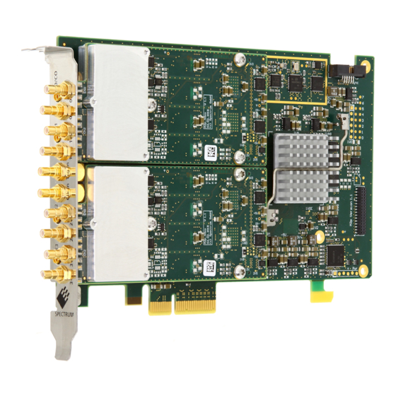
Image 2: M2p card and front panel for versions with two differential channels • M2p.5912-x4 • M2p.5922-x4 • M2p.5932-x4 • M2p.5942-x4 • M2p.5962-x4 Image 3: M2p card and front panel for versions with two differential channels / four single-ended channels (c) Spectrum Instrumentation GmbH... -
Page 14: Image 4: M2P Card And Front Panel For Versions With Four Differential Channels
Image 4: M2p card and front panel for versions with four differential channels • M2p.5913-x4 • M2p.5923-x4 • M2p.5933-x4 • M2p.5943-x4 • M2p.5968-x4 Image 5: M2p card and front panel for versions with four differential channels / eight single-ended channels (c) Spectrum Instrumentation GmbH... -
Page 15: Additional Options
All sixteen lines are provided via the multi- pin FX2 connector, a type that is already used on many different Spectrum products in the past and pin-compatible to the exist- ing options and cards using it. The pinning... -
Page 16: Star-Hub
The cable connection of the boards is automatically recognized and checked by the driver when initializing the star-hub module. So no care must be taken on how to cable the cards. The star-hub module itself is handled as an additional device just like any other card and the pro- gramming consists of only a few additional commands. (c) Spectrum Instrumentation GmbH... -
Page 17: The Spectrum Type Plate
Table 3: M2p card backside with the Spectrum type plate and information The Spectrum type plate, which consists of the following components, can be found on all of our boards. Please check whether the printed information is the same as the information on your delivery note. All this information can also be read out by software: The board type, consisting of the two letters describing the bus (in this case M2p.xxxx-x4 for the PCI Express x4 bus) and the model... -
Page 18: Hardware Information
Hardware information Introduction Hardware information Block Diagrams M2p.59xx Block Diagram Image 9: Block DIagram of M2p.59xx showing the analog module (green) and the components of the base card. The optional star-hub is shown in red (c) Spectrum Instrumentation GmbH... -
Page 19: Technical Data
X1/X2/X3 inputs at trigger time, trigger source (for OR trigger) Size per stamp 128 bit = 16 bytes X1, X2, X3 External trigger External trigger type Single level comparator 3.3V LVTTL logic inputs (c) Spectrum Instrumentation GmbH... - Page 20 Connectors on bracket 10 x SMB male (X4 to X13) Internal connectors 6 x SMB male (X14 to X19) Output: impedance Output: drive strength Capable of driving 50 loads, maximum drive strength ±48 mA (c) Spectrum Instrumentation GmbH...
- Page 21 > 700 MB/s (measured with a chipset supporting a TLP size of 256 bytes, using PCIe x4 Gen1) (Card-to-System: M2p.59xx or M2p.75xx) Sustained streaming mode > 700 MB/s (measured with a chipset supporting a TLP size of 256 bytes, using PCIe x4 Gen1) (System-to-Card: M2p.65xx or M2p.75xx) (c) Spectrum Instrumentation GmbH...
- Page 22 5 years starting with the day of delivery Software and firmware updates Life-time, free of charge Power Consumption 3.3V Total M2p.59x0, 59x1, 59x2 0.1 A 1.1 A 13.6 W M2p.59x3, 59x6, 59x8 0.1 A 1.5 A 18.4 W MTBF MTBF 100000 hours (c) Spectrum Instrumentation GmbH...
- Page 23 13.9 LSB 14.1 LSB 14.2 LSB 14.5 LSB 14.0 LSB 14.6 LSB 14.1 LSB 14.6 LSB ENOB (based on SINAD) 13.5 LSB 13.7 LSB 13.6 LSB 14.0 LSB 13.6 LSB 14.2 LSB 13.8 LSB 14.3 LSB (c) Spectrum Instrumentation GmbH...
- Page 24 PC. SNR = Signal to Noise Ratio, THD = Total Harmonic Distortion, SFDR = Spurious Free Dynamic Range, SINAD = Signal Noise and Dis- tortion, ENOB = Effective Number of Bits. (c) Spectrum Instrumentation GmbH...
-
Page 25: Order Information
16 additional multi-purpose I/O lines, 10 on separate slot bracket, 6 internal connectors M2p-upgrade Upgrade for M2p.xxxx: Later installation of options Star-Hub or Dig. Services Order no. Recal Recalibration at Spectrum incl. calibration protocol Cables Order no. for Connections Length to BNC male... - Page 26 Remote Server Software Package - LAN remote access for M2i/M3i/M4i/M4x/M2p cards SPc-SCAPP Spectrum’s CUDA Access for Parallel Processing - SDK for direct data transfer between Spectrum card and CUDA GPU. Includes RDMA activation and examples. : Just one of the options can be installed on a card at a time.
-
Page 27: Hardware Installation
Hardware Installation ESD Precautions All Spectrum boards contain electronic components that can be damaged by electrostatic discharge (ESD). Before installing the board in your system or protective conductive packaging, discharge yourself by touching a grounded bare metal surface or approved anti-static mat before picking up this ESD sensitive product. -
Page 28: M2P Pcie Cards
Before installing the board you first need to unscrew and remove the dedicated blind-bracket usually mounted to cover unused slots of your PC. Please keep the screw in reach to fasten your Spectrum card afterwards. All Spectrum M2p cards mechanically require one PCI Express x4, x8 or x16 slot (electrically either x1, x4, x8 or x16). -
Page 29: Additional Notes For M2P Main Cards With Heat-Sink Requiring Two Slots
Before installing the board you first need to unscrew and remove the dedicated blind-bracket usually mounted to cover unused slots of your PC. Please keep the screw in reach to fasten your Spectrum card afterwards. All Spectrum M2p cards mechanically require one PCI Express x4, x8 or x16 slot (electrically either x1, x4, x8 or x16). -
Page 30: Installing Multiple Boards Synchronized By Star-Hub Option
PC. Please keep the screws in reach to fasten your Spectrum cards afterwards. Spectrum M2p cards with the option „M2p.xxxx-SH6tm“ or „M2p.xxxx-SH16tm“ installed require two slots with ½ PCIe length, whilst M2p cards with the option „M2p.xxxx-SH6ex“ or „M2p.xxxx-SH16ex“ installed require one single ¾ PCIe length PCIe slot. -
Page 31: Software Driver Installation
Microsoft Website for available matching driver modules. Prior to running the Spectrum installer, the card will appear in the Windows device manager as a generalized card, shown here is the device manager of a Windows 10 as an example. -
Page 32: After Installation
Image 17: Spectrum Driver Installer - Progress Image 18: Spectrum Driver Installer - finished After installation After running the Spectrum driver installer, the card will appear in the Windows device manager with its name matching the card se- ries. The card is now ready to be used. -
Page 33: Linux
Unfortunately this won’t work in most cases as most Linux system refuse to load a driver which is not exactly matching. In this case it is possible to get the kernel driver sources from Spectrum. Please contact your local sales representative to get more details on this procedure. -
Page 34: Standard Driver Update
_drv_v123b4567) and only use the libraries out of this or one downloads the library package which is much smaller and doesn’t contain the pre-compiled kernel driver module (spcm_linux_lib_v123b4567). The update is done with a dedicated script which only updates the library file. This script is present in both driver archives: sh install_libonly.sh (c) Spectrum Instrumentation GmbH... -
Page 35: Installing The Library Only Without A Kernel (For Remote Devices)
To start programming the cards under Linux please use the standard C/C++ examples which are all running under Linux and Windows. Control Center The Spectrum Control Center is also available for Linux and needs to be installed sep- arately. The features of the Control Center are described in a later chapter in deeper detail. - Page 36 You may then run ldconfig. If this still doesn’t help please add the library path to /etc/ld.so.conf and run ldconfig again. If the libspcm_linux.so is quoted as missing please make sure that you have installed the card driver properly before. If any other library is stated as missing please install the matching package of your distribution. (c) Spectrum Instrumentation GmbH...
-
Page 37: Software
Image 21: Spectrum Kernel Driver, API Library and Software structure The Spectrum drivers offer you a common and fast API for using all of the board hardware features. This API is the same on all supported operating systems. Based on this API one can write own programs using any programming language that can access the driver API. This manual describes in detail the driver API, providing you with the necessary information to write your own programs. -
Page 38: Discovery Of Remote Cards, Digitizernetbox/Generatornetbox/Hybridnetbox Products
Card Control Center Software Discovery of Remote Cards, digitizerNETBOX/generatorNETBOX/hybridNETBOX products The Discovery function helps you to find and identify the Spectrum LXI instruments like digitizerNETBOX, generatorNETBOX or hybridNETBOX available to your computer on the network. The Dis- covery function will also locate Spectrum card products handled by an installed Spectrum Remote Server somewhere on the network. -
Page 39: Netbox Monitor
• Starting manually from the Spectrum Control Center using the context menu as shown above • Starting from command line. The Netbox Monitor program is automatically installed together with the Spectrum Control Center and is located in the selected install folder. Using the command line tool one can place a simple script into the autostart folder to have the Net- box Monitor running automatically after system boot. -
Page 40: Hardware Information
The procedure on how to update the firmware of your digitizerNETBOX/generatorNETBOX/hybridNETBOX with the help of the integrated Webserver is described in a dedi- cated chapter later on. Image 28: Spectrum Control Center - showing firmware information of an installed card (c) Spectrum Instrumentation GmbH... -
Page 41: Software License Information
The number of demo starts left can be seen here. Image 29: Spectrum Control Center - showing firmware information of an installed card Driver information The Spectrum card control center also offers a way to gather information on the installed and used Spectrum driver. -
Page 42: Installing And Removing Demo Cards
Installing and removing Demo cards With the help of the card control center one can install demo cards in the system. A demo card is simulated by the Spectrum driver in- cluding data production for acquisition cards. As the demo card is... -
Page 43: Performing Memory Test
28000000] = 112000000 Bytes/second. Taking the above figures measured on a standard 33 MHz PCI slot the system is just capable of reaching this transfer speed: 108.0 MB/s = 108 * 1024 * 1024 = 113246208 Bytes/second. Unfortunately it is not possible to measure transfer speed on a system without having a Spectrum card installed. Debug logging for support cases... -
Page 44: Device Mapping
Card Control Center Software Device mapping Within the „Device mapping“ tab of the Spectrum Control Center, one can ena- ble the re-mapping of Spectrum devices, be it either local cards, remote instru- ments such as a digitizerNETBOX, generatorNETBOX, hybridNETBOX or even cards in a remote PC and accessed via the Spectrum remote server option. -
Page 45: Accessing The Hardware With Sbench 6
Contains all error codes used with the Spectrum driver. All error codes that can be given back by any of the driver functions are also described here briefly. The error codes and their meaning are described in detail in the appendix of this manual. -
Page 46: General Information On Windows 64 Bit Drivers
General Information on Windows 64 bit drivers After installation of the Spectrum 64 bit driver there are two general ways to access the hardware and to de- velop applications. If you’re going to develop a real 64 bit application it is necessary to access the 64 bit driver dll (spcm_win64.dll) as only this driver dll is supporting the full 64 bit address range. -
Page 47: Linux Gnu C/C++ 32/64 Bit
This allows us to use platform independent and universal examples and driver interfaces. If you do not stick to these declarations please be sure to use the same data type width. However it is strongly recommended that you use our defined (c) Spectrum Instrumentation GmbH... -
Page 48: Table 5: C/C++ Type Declarations For Drivers And Examples
Be sure to close the driver if you don’t need it any more to allow other programs to get access to this device. Function spcm_vClose: void _stdcall spcm_vClose ( // closes the device drv_handle hDevice); // handle to an already opened device (c) Spectrum Instrumentation GmbH... - Page 49 The three functions only differ in the type of the parameters that are used to call them. As some of the registers can exceed the 32 bit integer range (like memory size or post trigger) it is recommended to use the _i64 function to access these registers. However as there are some (c) Spectrum Instrumentation GmbH...
-
Page 50: Table 7: Spectrum Driver Api Functions Overview And Differentiation Between 32 Bit And 64 Bit Registers
If accessing 64 bit registers with 32 bit functions the behavior differs depending on the real value that is currently located in the register. Please have a look at this table to see the different reactions depending on the size of the register: Table 7: Spectrum driver API functions overview and differentiation between 32 bit and 64 bit registers Internal register read/write... - Page 51 // address of the error register (can be zero if not of interest) int32* plErrorValue, // address of the error value (can be zero if not of interest) char pszErrorTextBuffer[ERRORTEXTLEN]); // text buffer for text error (c) Spectrum Instrumentation GmbH...
- Page 52 Driver functions Software Example: char szErrorBuf[ERRORTEXTLEN]; if (spcm_dwSetParam_i64 (hDrv, SPC_MEMSIZE, -1)) spcm_dwGetErrorInfo_i32 (hDrv, NULL, NULL, szErrorBuf); printf (“Set of memsize failed with error message: %s\n”, szErrorBuf); (c) Spectrum Instrumentation GmbH...
-
Page 53: Delphi (Pascal) Programming Interface
Besides including the driver files in the project it is also necessary to include them in the uses section of the source files where functions or constants should be used: uses Windows, Messages, SysUtils, Classes, Graphics, Controls, Forms, Dialogs, StdCtrls, ExtCtrls, SpcRegs, SpcErr, spcm_win32; Image 41: Structure of the Delphi ex- maples (c) Spectrum Instrumentation GmbH... -
Page 54: Examples
The example implements a very simple scope program that makes single acquisitions on button pressing. A fixed setup is done inside the example. The spcm_scope example can be used with any analog data acquisition card from Spectrum. It covers cards with 1 byte per sample... -
Page 55: Net Programming Languages
Library For using the driver with a .NET based language Spectrum delivers a special library that encapsulates the driver in a .NET object. By adding this object to the project it is possible to access all driver functions and constants from within your .NET environment. -
Page 56: Using Managed C++/Cli
System.out.println("Error: Could not open card\n"); else // ----- get card type ----- dwErrorCode = Drv.spcm_dwGetParam_i32(hDevice, Regs.SPC_PCITYP, lCardType); dwErrorCode = Drv.spcm_dwGetParam_i32(hDevice, Regs.SPC_PCISERIALNR, lSerialNumber); Example for digitizerNETBOX/generatorNETBOX and remotely installed cards: ' ----- open remote card ----- hDevice = Drv.spcm_hOpen("TCPIP::192.168.169.14::INST0::INSTR") (c) Spectrum Instrumentation GmbH... -
Page 57: Python Programming Interface And Examples
# use cdll because all driver access functions use cdecl calling convention under linux spcmDll = cdll.LoadLibrary ("libspcm_linux.so") # the loading of the driver access functions is similar to windows: # load spcm_hOpen spcm_hOpen = getattr (spcmDll, "spcm_hOpen") spcm_hOpen.argtype = [c_char_p] spcm_hOpen.restype = drv_handle # ... (c) Spectrum Instrumentation GmbH... -
Page 58: Examples
Please feel free to use these examples as a base for your programs and to modify them in any kind. When allocating the buffer for DMA transfers, use the following function to get a mutable character buffer: ctypes.create_string_buffer(init_or_size[, size]) (c) Spectrum Instrumentation GmbH... -
Page 59: Java Programming Interface And Examples
Examples for Java can be found on CD in the directory /examples/java. The directory contains the above mentioned header files and some examples, each of them working with a certain type of card. Please feel free to use these examples as a base for your programs and to modify them in any kind. (c) Spectrum Instrumentation GmbH... -
Page 60: Julia Programming Interface And Examples
Examples for Julia can be found on USB-Stick in the directory /examples/julia. The directory contains the above mentioned include files and some examples, each of them working with a certain type of card. Please feel free to use these examples as a base for your programs and to modify them in any kind. (c) Spectrum Instrumentation GmbH... -
Page 61: Labview Driver And Examples
CUDA Remote Direct Memory Access (RDMA) can be used to directly transfer data from/to a Spectrum Digitizer/Generator to/from a GPU card for processing, thus avoiding the transfer of raw data to the host memory and benefiting from the computational power of the GPU. -
Page 62: Programming The Board
C/C++, Delphi and Basic com- ten (w). above or below the register ta- bles. Table 8: Spectrum API: Command register and basic commands Register Value Direction Description SPC_M2CMD Command register of the board. -
Page 63: Initialization
// Opens the remote board #1 hDrv = spcm_hOpen ("TCPIP::192.168.169.14::INST2::INSTR"); // Opens the remote board #2 Error handling If one action caused an error in the driver this error and the register and value where it occurs will be saved. (c) Spectrum Instrumentation GmbH... -
Page 64: Gathering Information From The Card
All information can be read out using one of the spcm_dwGetParam functions. Please stick to the “Driver Functions” chapter for more details on this function. (c) Spectrum Instrumentation GmbH... -
Page 65: Card Type
Please don’t rely on the card ordering as this is based on the BIOS, the bus connections and the operating system. Table 9: Spectrum API: Card Type Register Register... -
Page 66: Hardware And Pcb Version
Hardware and PCB version Since all of the boards from Spectrum are modular boards, they consist of one base board and one piggy-back front-end module and even- tually of an extension module like the star-hub. Each of these three kinds of hardware has its own version register. Normally you do not need this information but if you have a support question, please provide the revision together with it. -
Page 67: Production Date
1. Cards that do provide a golden recovery image for the main control FPGA, the currently booted firmware can additionally read out: Table 15: Spectrum API: Register overview of reading current firmware Register... -
Page 68: Serial Number
Is set in the card that carries a System Star-Hub Slave module to connect with System Star-Hub master systems (M2i). SPCM_FEAT_NETBOX 8000h The card is physically mounted within a digitizerNETBOX or generatorNETBOX. SPCM_FEAT_REMOTESERVER 10000h Support for the Spectrum Remote Server option is installed on this card. (c) Spectrum Instrumentation GmbH... -
Page 69: Miscellaneous Card Information
Installed extended Options and Features Some cards (such as M4i/M4x/M2p cards) can have advanced features and options installed. This can be read out with with the following register: Table 17: Spectrum API: Extended feature register and available extended feature flags Register Value... -
Page 70: Used Type Of Driver
Custom modifications Since all of the boards from Spectrum are modular boards, they consist of one base board and one piggy-back front-end module and even- tually of an extension module like the Star-Hub. Each of these three kinds of hardware has its own version register. Normally you do not need this information but if you have a support question, please provide the revision together with it. -
Page 71: Reset
Reset Every Spectrum card can be reset by software. Concerning the hardware, this reset is the same as the power-on reset when starting the host computer. In addition to the power-on reset, the reset command also brings all internal driver settings to a defined default state. A software reset is automatically performed, when the driver is first loaded after starting the host system. -
Page 72: Analog Inputs
Channel Selection One key setting that influences all other possible settings is the channel enable register. A unique feature of the Spectrum cards is the possibility to program the number of channels you want to use. All on-board memory can then be used by these activated channels. -
Page 73: Differential Inputs
As a result all the offset settings mentioned before can only be used with single-ended inputs. You can change between single-ended and differential mode separately for every even input channel by setting the relating register shown in one of the following tables: (c) Spectrum Instrumentation GmbH... -
Page 74: Mixed Single-Ended And Differential Inputs
Channel Selection Analog Inputs M2p.59x2, M2p.59x3: Table 24: Spectrum API: registers for differential mode setup, card with multiplexed channels (one differential or two single-ended) Register Value Direction Description SPC_DIFF0 30040 Set channel 0 to differential mode using channel 1 as negative input. The default mode is single-ended. -
Page 75: Setting Up The Inputs
Table 26: Spectrum API: input range register and available input range settings Register... -
Page 76: Input Offset
On this acquisition boards from Spectrum you have the pos- sibility to adjust the input offset separately for each channel. Image 46: Spectrum API: using the input offset shifting to optimize the usage of the input range The example in the right figure shows signals with a range of ±1.0 V that have offsets up to ±1.0 V. -
Page 77: Input Termination
As all settings are temporarily stored in the driver, the automatic adjustment will only affect these values. After exiting your program, all cali- bration information will be lost. To give you a possibility to save your own settings, most Spectrum card have at least one set of user settings... -
Page 78: Read Out Of Input Features
Please note that the following table shows all input features settings that are available throughout all Spectrum acquisition cards. Some of these features are not installed on your specific hardware. -
Page 79: Acquisition Modes
9501 read Returns a bitmap with all available modes on your card. The modes are listed below. Acquisition modes Table 34: Spectrum API: possible values for the card mode register. Description of the different card modes Mode Value Available on... -
Page 80: Commands
As not all of the command combinations make sense (like the combination of reset and start at the same time) the driver will check the given command and return an error code ERR_SEQUENCE if one of the given commands is not allowed in the current state. Table 35: Spectrum API: card command register and different commands with descriptions Register... -
Page 81: Card Status
SPC_M2STATUS register. The status register is organized as a bitmap, so that multiple bits can be set, showing the status of the card and also of the different data transfers. Table 36: Spectrum API: card status register and possible status values with descriptions of the status Register... -
Page 82: Data Transfer
4 kByte. For data transfer it may also be a fraction of 4k in the range of 16, 32, 64, 128, 256, 512, 1k or 2k. No other values are allowed. For ABA and timestamp the notify (c) Spectrum Instrumentation GmbH... -
Page 83: Table 37: Spectrum Api: Command Register And Commands For Dma Transfers
M2CMD_DATA_STOPDMA 40000h Stops a running DMA transfer. Data is invalid afterwards. The data transfer can generate one of the following status information: Table 38: Spectrum API: status register and status codes for DMA data transfer Register Value Direction Description... -
Page 84: Standard Single Acquisition Mode
The standard single mode is the easiest and mostly used mode to acquire analog data with a Spectrum acquisition card. In standard single recording mode the card is working totally independent from the PC, after the card setup is done. The advantage of the Spectrum boards is that regardless to the system usage the card will sample with equidistant time intervals. -
Page 85: Example
In standard mode the acquisition length is defined before the start and is limited to the installed on-board memory whilst in FIFO mode the acquisition length can either be defined or it can run continuously until user stops it. (c) Spectrum Instrumentation GmbH... -
Page 86: Example Fifo Acquisition
(Limited by max pretrigger) post) FIFO Gate not used 8G - 8 not used 0 () 4G - 1 4 Ch Standard Single Mem/4 Mem/4 - 8 8G - 16 not used not used (defined by mem and post) (c) Spectrum Instrumentation GmbH... -
Page 87: Buffer Handling
The following drawing will give you an overview of the structure of the data transfer handling: Image 52: Overview of buffer handling for DMA transfers showing and the interaction with the DMA engine (c) Spectrum Instrumentation GmbH... -
Page 88: Table 40: Spectrum Api: Registers For Dma Buffer Handling
Internally the card handles two counters, a user counter and a card counter. Depending on the transfer direction the software registers have slightly different meanings: Table 41: Spectrum API: content of DMA buffer handling registers for different use cases Transfer direction... - Page 89 This buffer handling can now continue endless as long as we manage to set the data available for the card fast enough. The USER_POS and USER_LEN for step 8 would now look exactly as the buffer shown in step 2. (c) Spectrum Instrumentation GmbH...
- Page 90 However the DATA_AVAIL_USER_LEN register will give you the com- plete amount of available bytes even if one part of the free area is at the end of the buffer and the second half at the beginning of the buffer. (c) Spectrum Instrumentation GmbH...
-
Page 91: Data Organization
Data is organized in a multiplexed way in the transfer buffer. If using 2 channels data of first activated channel comes first, then data of second channel. Table 42: Spectrum API: overview of data organization in memory for different channel configurations Activated... -
Page 92: Converting Adc Samples To Voltage Values
Converting ADC samples to voltage values The Spectrum driver also contains a register that holds the value of the decimal value of the full scale representation of the installed ADC. This value should be used when converting ADC values (in LSB) into real-world voltage values, because this register also automatically takes any specialities into account, such as slightly reduced ADC resolution with reserved codes for gain/offset compensation. -
Page 93: Clock Generation
Synchronization Clock (option Star-Hub) The Star-Hub option allows the synchronization of up to 16 cards of the M2p series from Spectrum with a minimal phase delay between the different cards. The clock is distributed from the master card to all connected cards. As this clock is also available at the PLL input, cards of the same or slower sampling speeds can be synchronized with different sample rates when using the PLL. -
Page 94: Maximum And Minimum Internal Sampling Rate
An external clock can be fed in on the external clock connector of the board. This can be any clock, that matches the specification of the card. The external clock signal can be used to synchronize the card on a system clock or to feed in an exact matching sampling rate. Table 48: Spectrum API: software clock mode register and external clock settings Register... -
Page 95: External Reference Clock
(such as 1.5V LVTTL, 3.3V LVTTL, 5VTTL etc) as well as to allow to detect an externally AC-coupled clock by setting the level to 0 mV. The threshold levels for the external clock is to be programmed in mV: Table 50: Spectrum API: clock threshold software registers and available range therefore Register... -
Page 96: Table 53: Spectrum Api: Clock Threshold Software Registers And Available Range Therefore
(such as 1.5V LVTTL, 3.3V LVTTL, 5VTTL etc) as well as to allow to detect an externally AC-coupled clock by setting the level to 0 mV. The threshold levels for the external clock is to be programmed in mV: Table 53: Spectrum API: clock threshold software registers and available range therefore Register... -
Page 97: Trigger Modes And Appendant Registers
Trigger modes and appendant registers General Description The trigger modes of the Spectrum M2p series A/D and D/A cards are very extensive and give you the possibility to detect nearly any trigger event you can think of. You can choose between various external trigger modes as well as internal trigger modes (on analog acquisition cards) including software and channel trigger, depending on your type of board. -
Page 98: Trigger Masks
Image 56: trigger OR mask details The table below shows the relating register for the general OR mask and the possible constants that can be written to it. Table 54: Spectrum API: external trigger OR mask related software register and available settings Register Value... -
Page 99: Trigger And Mask
The table below is showing the registers for the channel OR mask (A/D cards only) and the possible constants that can be written to it. Table 55: Spectrum API: channel trigger OR mask related software register and available settings Register... -
Page 100: Software Trigger
Trigger modes and appendant registers The table below shows the relating register for the general AND mask and the possible constants that can be written to it. Table 56: Spectrum API: external trigger AND mask related software register and available settings Register... -
Page 101: Force- And Enable Trigger
(hDrv, SPC_M2CMD, M2CMD_CARD_DISABLETRIGGER); // Trigger engine is disarmed. Trigger delay All of the Spectrum M2p series cards allow the user to program an additional trigger delay. As shown in the trigger overview section, this delay is the last element in the trigger chain. Therefore the user does not have to care for the sources when programming the trigger delay. -
Page 102: Trigger Holdoff
Trigger holdoff All the cards of the Spectrum M2p series allow the user to program a trigger holdoff time when using one of the segmented acquisition or generation modes, such as Multiple Recording/Multiple Replay, ABA Mode (analog acquisition cards only) or Gated Sampling/Gated Re- play. -
Page 103: Trigger Mode
Main analog external trigger (Ext0) Trigger Mode Please find the main external (analog) trigger input modes below. A detailed description of the modes follows in the next chapters.. Table 63: Spectrum API: external trigger mode registers and available settings therefore Register Value... - Page 104 This edge triggered external trigger mode correspond to the trigger possibilities of usual oscilloscopes. Register Value Direction set to Value SPC_TRIG_EXT0_MODE 40510 read/write SPC_TM_NEG SPC_TRIG_EXT0_LEVEL0 42320 read/write Set it to the desired trigger level in mV (c) Spectrum Instrumentation GmbH...
- Page 105 The trigger event will be detected if the trigger input is below the programmed trigger level. Register Value Direction set to Value SPC_TRIG_EXT0_MODE 40510 read/write SPC_TM_LOW 00000010h SPC_TRIG_EXT0_LEVEL0 42320 read/write Set it to the upper trigger level in mV (c) Spectrum Instrumentation GmbH...
- Page 106 SPC_TM_POS | SPC_TM_PW_SMALLER 02000001h SPC_TRIG_EXT0_LEVEL0 42320 read/write Set it to the desired trigger level in mV SPC_TRIG_EXT0_PULSEWIDTH 44210 read/write Sets the pulsewidth in samples. Values from 2 to [4G -1] are allowed. 2 to [4G -1] (c) Spectrum Instrumentation GmbH...
- Page 107 // Setting up external X0 TTL trigger to detect low pulses that are below 1500 mV longer than 50 samples ... spcm_dwSetParam_i32 (hDrv,SPC_TRIG_EXT0_LEVEL0, 1500); spcm_dwSetParam_i32 (hDrv,SPC_TRIG_EXT0_MODE, SPC_TM_NEG | SPC_TM_PW_GREATER); spcm_dwSetParam_i64 (hDrv, SPC_TRIG_EXT1_PULSEWIDTH , 50); spcm_dwSetParam_i32 (hDrv, SPC_TRIG_ORMASK, SPC_TMASK_EXT1); // ... and enable it in OR mask (c) Spectrum Instrumentation GmbH...
-
Page 108: External Logic Trigger (X1, X2, X3)
W_SMALLER width. For all external edge and level trigger modes, the OR mask must contain the corresponding input, as the following table shows: Table 68: Spectrum API: trigger OR mask register an settings for external logic trigger Register Value Direction... -
Page 109: Detailed Description Of The Logic Trigger Modes
The next trigger event will then be detected, if the actual record- ing/replay has finished and the board is armed and waiting for a trigger again. Register Value Direction set to Value SPC_TRIG_EXT1_MODE 40511 read/write SPC_TM_LOW SPC_TRIG_EXT2_MODE 40512 SPC_TRIG_EXT3_MODE 40513 (c) Spectrum Instrumentation GmbH... - Page 110 Register Value Direction set to Value SPC_TRIG_EXT1_PULSEWIDTH 44211 read/write Sets the pulsewidth in samples. 2 up to [4G -1] SPC_TRIG_EXT2_PULSEWIDTH 44212 SPC_TRIG_EXT3_PULSEWIDTH 44213 SPC_TRIG_EXT1_MODE 40511 read/write (SPC_TM_POS | SPC_TM_PW_SMALLER) 2000001h SPC_TRIG_EXT2_MODE 40512 SPC_TRIG_EXT3_MODE 40513 (c) Spectrum Instrumentation GmbH...
- Page 111 To find out what maximum pulsewidth (in samples) is available, please read out the register shown in the table below: Register Value Direction Description SPC_TRIG_EXT_AVAILPULSEWIDTH 44201 read Contains the maximum possible value for the external trigger pulsewidth counter. Valid for all of the external trigger sources. (c) Spectrum Instrumentation GmbH...
-
Page 112: Channel Trigger
So it can be that you have less channels installed on your specific card and therefore have less valid channel mode registers. If you try to set a channel, that is not installed on your specific card, an error message will be returned. Table 69: Spectrum API: channel trigger register and available settings for these Register... -
Page 113: Channel Trigger Level
The table further below gives you the absolute trigger levels for your specific card series. 16 bit resolution for the trigger levels: Table 70: Spectrum API: channel trigger level registers Register Value... -
Page 114: Table 71: Spectrum Api: Standard Input Ranges And Representation Of Trigger Level Settings In Voltage
Reading out the number of possible trigger levels The Spectrum driver also contains a register that holds the value of the maximum possible different trigger levels considering the above men- tioned exclusion of the most negative possible value. This is useful, as new drivers can also be used with older hardware versions, because you can check the trigger resolution during run time. -
Page 115: Detailed Description Of The Channel Trigger Modes
These edge triggered channel trigger modes correspond to the trigger possibilities of usual oscilloscopes. Register Value Direction set to Value SPC_TRIG_CH0_MODE 40610 read/write SPC_TM_BOTH SPC_TRIG_CH0_LEVEL0 42200 read/write Set it to the desired trigger level relatively to the channel’s input range. board dependant (c) Spectrum Instrumentation GmbH... - Page 116 Set it to the desired trigger level relatively to the channel’s input range. board dependant SPC_TRIG_CH0_PULSEWIDTH 44101 read/write Sets the pulsewidth in samples. Values from 2 to [4G -1] are allowed. 2 to [4G -1] (c) Spectrum Instrumentation GmbH...
- Page 117 Set it to the desired trigger level relatively to the channel’s input range. board dependant SPC_TRIG_CH0_PULSEWIDTH 44101 read/write Sets the pulsewidth in samples. Values from 2 to [4G -1] are allowed. 2 to [4G -1] (c) Spectrum Instrumentation GmbH...
- Page 118 Set it to the lower trigger level relatively to the channel’s input range. board dependant SPC_TRIG_CH0_PULSEWIDTH 44101 read/write Sets the pulsewidth in samples. Values from 2 to [4G -1] are allowed. 2 to [4G -1] (c) Spectrum Instrumentation GmbH...
- Page 119 Set it to the lower trigger level relatively to the channel’s input range. board dependant SPC_TRIG_CH0_PULSEWIDTH 44101 read/write Sets the pulsewidth in samples. Values from 2 to [4G -1] are allowed. 2 to [4G -1] (c) Spectrum Instrumentation GmbH...
- Page 120 21000001h SPC_TRIG_CH0_LEVEL0 42200 read/write Set it to the desired trigger level relatively to the channel’s input range. board dependant SPC_TRIG_CH0_LEVEL1 42300 read/write Defines the re-arm and hysteresis level relatively to the channel’s input board dependant range (c) Spectrum Instrumentation GmbH...
- Page 121 SPC_TM_LOW | SPC_TM_HYSTERESIS 20000010h SPC_TRIG_CH0_LEVEL0 42200 read/write Set it to the desired trigger level relatively to the channel’s input range. board dependant SPC_TRIG_CH0_LEVEL1 42300 read/write Defines the hysteresis level relatively to the channel’s input range board dependant (c) Spectrum Instrumentation GmbH...
- Page 122 Set the difference between two samples relatively to the channel’s input board dependant range for positive slopes. SPC_TRIG_CH0_LEVEL1 42300 read/write Set the difference between two samples relatively to the channel’s input board dependant range for negative slopes. (c) Spectrum Instrumentation GmbH...
-
Page 123: Multi Purpose I/O Lines
SPCM_X1_AVAILMODES, SPCM_X2_AVAILMODES and SPCM_X3_AVAILMODES register first. The available modes may differ from card to card and may be enhanced with new driver/firmware versions to come. Table 72: Spectrum API: XIO lines and mode software registers with their available settings Register... -
Page 124: Asynchronous I/O
- SPCM_X1_MODE = SPCM_X2_MODE = SPCM_X3_MODE = SPCM_XMODE_DISABLE The SPC_TRIG_OUTPUT register overrides the multi purpose I/O settings done by SPCM_X1_MODE, SPCM_X- 2_MODE and SPCM_X3_MODE and vice versa. Do not use both methods together from within one program. (c) Spectrum Instrumentation GmbH... -
Page 125: Synchronous Digital Inputs
Sample Format Any channels that will not store any digital inputs within their samples still provide the full 16 bit resolution. : Table 74: Spectrum API: data organization for different digital input option configurations Standard Mode 1 digital input enabled... - Page 126 // add three sources (X1, X2 and X3) at three different positions (bit15, bit14 and bit13) dwValue |= (DIGMODEMASK_BIT15 & SPCM_DIGMODE_X3); dwValue |= (DIGMODEMASK_BIT14 & SPCM_DIGMODE_X2); dwValue |= (DIGMODEMASK_BIT13 & SPCM_DIGMODE_X1); // and write value to channel 0 digmode register. Resulting Ch0 A/D samples will be 13bit. spcm_dwSetParam_i32 (hDrv, SPCM_DIGMODE0, dwValue); (c) Spectrum Instrumentation GmbH...
-
Page 127: Additional I/O Lines With Option -Digsmb And -Digfx2
SPCM_X19_AVAILMODES register first. The available modes may differ from card to card and may be enhanced with new driver/firm- ware versions to come. Table 75: Spectrum API: mode registers for XIO lines on additional digital I/O module and their settings Register... -
Page 128: Asynchronous I/O
The mask and mode and mode values have to properly be combined. This is shown in the example below the tables: Table 76: Spectrum API: registers for synchronous digital inputs Register Value... -
Page 129: Table 77: Spectrum Api: Data Organization For Different Digital Input Option Configurations
Sample Format (with up to 3 digital channels) Any channels that will not store any digital inputs within their samples still provide the full 16 bit resolution. : Table 77: Spectrum API: data organization for different digital input option configurations Standard Mode... -
Page 130: Table 78: Sample Format Of Analog Samples In Combination With Digital Input Channels
// store X8 in Sample Bit13 dwValue |= (DIGMODEMASK_BIT12 & SPCM_DIGMODE_X13); // store X13 in Sample Bit12 // and write value to channel 0 digmode register. Resulting Ch0 A/D samples will be 12bit. spcm_dwSetParam_i32 (hDrv, SPCM_DIGMODE0, dwValue); (c) Spectrum Instrumentation GmbH... -
Page 131: Mode Multiple Recording
Image 65: Drawing of Multiple Recording acquisition The following table shows the register for defining the structure of the segments to be recorded with each trigger event. Table 79: Spectrum API: software registers for Multiple Recording mode setup Register Value... -
Page 132: Limits Of Pre Trigger, Post Trigger, Memory Size
FIFO Gate not used 8G - 16 not used 0 () 4G - 1 All figures listed here are given in samples. An entry of [8G - 16] means [8 GSamples - 16] = 8,589,934,576 samples. (c) Spectrum Instrumentation GmbH... -
Page 133: Multiple Recording And Timestamps
• Issue a number of Force Trigger commands to fill the complete memory (standard mode) or to transfer the last FIFO block that contains valid data segments • Use the trigger counter value to split the acquired data into valid data with a real trigger event and invalid data with a force trigger event. (c) Spectrum Instrumentation GmbH... -
Page 134: Programming Examples
// the pretrigger will be 128 samples spcm_dwSetParam_i64 (hDrv, SPC_LOOPS 256); // 256 segments will be recorded spcm_dwSetParam_i32 (hDrv, SPC_TRIG_EXT0_MODE, SPC_TM_NEG); // Set triggermode to ext. TTL mode (falling edge) spcm_dwSetParam_i32 (hDrv, SPC_TRIG_ORMASK, SPC_TMASK_EXT0); // and enable it within the trigger OR-mask (c) Spectrum Instrumentation GmbH... -
Page 135: Mode Gated Sampling
When using Gated Sampling the maximum pretrigger is limited as shown in the technical data section. When the programmed value exceeds that limit, the driver will return the error ERR_PRETRIGGERLEN. Table 81: Spectrum API: registers and settings for Gated Sampling mode Register... -
Page 136: Limits Of Pre Trigger, Post Trigger, Memory Size
All figures listed here are given in samples. An entry of [8G - 16] means [8 GSamples - 16] = 8,589,934,576 samples. The given memory and memory / divider figures depend on the installed on-board memory as listed below: Installed Memory 512 MSample 512 MSample Mem/2 256 MSample Mem/4 128 MSample Mem/8 64 MSample (c) Spectrum Instrumentation GmbH... -
Page 137: Gate-End Alignment
Gate-End Alignment Due to the structure of the on-board memory, the length of a gate will be rounded up until the next card specific alignment: Table 83: Spectrum API: gate end alignement in Gated Sampling mode M2i + M2i-exp M4i + M4x... -
Page 138: Trigger
Detailed description of the external analog trigger modes For all external analog trigger modes shown below, either the OR mask or the AND must contain the external trigger to activate the external input as trigger source:. Table 84: Spectrum API: external analog trigger registers Register Value... - Page 139 The pulsewidth trigger modes for long pulses can be used to prevent the board from triggering on wrong (short) edges in noisy signals. Register Value Direction set to Value SPC_TRIG_CH0_MODE 40610 read/write SPC_TM_NEG | SPC_TM_PW_GREATER 04000002h (c) Spectrum Instrumentation GmbH...
-
Page 140: Detailed Description Of The Logic Gate Trigger Modes
As this mode is purely edge-triggered, the low level at the cards start time, does not trigger the board. With the next rising edge the gate will be stopped. Register Value Direction set to Value SPC_TRIG_EXT1_MODE 40511 read/write SPC_TM_NEG SPC_TRIG_EXT2_MODE 40512 SPC_TRIG_EXT3_MODE 40513 (c) Spectrum Instrumentation GmbH... - Page 141 // Setting up external X1 TTL trigger to detect low pulses that are longer than 50 samples ... spcm_dwSetParam_i32 (hDrv,SPC_TRIG_EXT1_MODE, SPC_TM_NEG | SPC_TM_PW_GREATER); spcm_dwSetParam_i64 (hDrv, SPC_TRIG_EXT1_PULSEWIDTH , 50); spcm_dwSetParam_i32 (hDrv, SPC_TRIG_ORMASK, SPC_TMASK_EXT1); // ... and enable it in OR mask (c) Spectrum Instrumentation GmbH...
-
Page 142: Channel Triggers Modes
Register Value Direction set to Value SPC_TRIG_CH0_MODE 40610 read/write SPC_TM_NEG SPC_TRIG_CH0_LEVEL0 42200 read/write Set it to the desired trigger level relatively to the channel’s input range. board dependant (c) Spectrum Instrumentation GmbH... - Page 143 40610 read/write SPC_TM_NEG | SPC_TM_REARM 01000002h SPC_TRIG_CH0_LEVEL0 42200 read/write Defines the re-arm level relatively to the channels’s input range board dependant SPC_TRIG_CH0_LEVEL1 42300 read/write Defines the re-arm level relatively to the channels’s input range board dependant (c) Spectrum Instrumentation GmbH...
- Page 144 SPC_TRIG_CH0_LEVEL0 42200 read/write Set it to the upper trigger level relatively to the channel’s input range. board dependant SPC_TRIG_CH0_LEVEL1 42300 read/write Set it to the lower trigger level relatively to the channel’s input range. board dependant (c) Spectrum Instrumentation GmbH...
- Page 145 SPC_TRIG_CH0_LEVEL0 42200 read/write Set it to the upper trigger level relatively to the channel’s input range. board dependant SPC_TRIG_CH0_LEVEL1 42300 read/write Set it to the lower trigger level relatively to the channel’s input range. board dependant (c) Spectrum Instrumentation GmbH...
- Page 146 SPC_TM_POS | SPC_TM_HYSTERESIS 20000001h SPC_TRIG_CH0_LEVEL0 42200 read/write Set it to the desired trigger level relatively to the channel’s input range. board dependant SPC_TRIG_CH0_LEVEL1 42300 read/write Defines the hysteresis level relatively to the channel’s input range board dependant (c) Spectrum Instrumentation GmbH...
- Page 147 SPC_TM_NEG | SPC_TM_REARM | SPC_TM_HYSTERESIS 21000002h SPC_TRIG_CH0_LEVEL0 42200 read/write Defines the re-arm level relatively to the channel’s input range board dependant SPC_TRIG_CH0_LEVEL1 42300 read/write Defines the re-arm and hysteresis level relatively to the channel’s input board dependant range (c) Spectrum Instrumentation GmbH...
-
Page 148: Programming Examples
(hDrv, SPC_TRIG_EXT0_MODE, SPC_TM_NEG); // Set triggermode to ext. TTL mode (falling edge) spcm_dwSetParam_i32 (hDrv, SPC_TRIG_EXT0_LEVEL0, -1500); // Set trigger level to -1500 mV spcm_dwSetParam_i32 (hDrv, SPC_TRIG_ORMASK, SPC_TMASK_EXT0); // and enable it within the trigger OR-mask (c) Spectrum Instrumentation GmbH... -
Page 149: Aba Mode (Dual Timebase)
The ABA mode needs a second clock base. As explained above the acquisition is not changing the sampling clock but runs the slower ac- quisition with a divided clock. The ABA memory setup including the divider value can be programmed with the following registers Table 85: Spectrum API: ABA settings restigerts Register... -
Page 150: Fifo Mode
FIFO Single not used not used 8G - 16 0 () 4G - 1 FIFO Multi/ABA not used 8G - 8 pre+post 0 () 4G - 1 (defined by segment and (Limited by max pretrigger) post) (c) Spectrum Instrumentation GmbH... -
Page 151: Example For Setting Aba Mode
// define the segmentsize, pre and posttrigger and the total amount of data to acquire spcm_dwSetParam_i64 (hDrv, SPC_MEMSIZE, 16384); spcm_dwSetParam_i64 (hDrv, SPC_SEGMENTSIZE, 2048); spcm_dwSetParam_i64 (hDrv, SPC_POSTTRIGGER, 1024); // set the trigger mode to external with positive edge spcm_dwSetParam_i32 (hDrv, SPC_TRIG_ORMASK, SPC_TMASK_EXT0); spcm_dwSetParam_i32 (hDrv, SPC_TRIG_EXT0_MODE, SPC_TM_POS); (c) Spectrum Instrumentation GmbH... -
Page 152: Reading Out Aba Data
As explained above the data transfer is performed with the same command and status registers like the card control and sample data transfer. It is possible to send commands for card control, data transfer and extra FIFO data transfer at the same time Table 87: Spectrum API: extra DMA commands (ABA and Timestamp) Register... -
Page 153: Table 89: Spectrum Api: Aba And Timestamp Dma Buffer Handling Registers
DMA from the hardware extra FIFO buffer and on the other hand it is handled by the user who set’s parts of this software buffer available for the driver for further transfer. The handshake is fulfilled with the following 3 software registers: Table 89: Spectrum API: ABA and Timestamp DMA buffer handling registers Register... -
Page 154: Data Transfer Using Polling
ER_LEN is read the driver will read out all available data from the hardware and will return the number of bytes that has been read. In min- imum this will be one DWORD = 4 bytes. (c) Spectrum Instrumentation GmbH... -
Page 155: Comparison Of Dma And Polling Commands
A samples) and the B area samples it is possible to let the card stamp the first A area sample automatically after the card start. The following ta- ble shows the register to enable this mode: Table 90: Spectrum API: timestamp command register and ABA mode settings Register Value... - Page 156 // additionally enable index of the first A area sample dwTimestampMode |= SPC_TSFEAT_STORE1STABA; spcm_dwSetParam_i32 (hDrv, SPC_TIMESTAMP_CMD, dwTimestampMode); The programming details of the ABA mode and timestamp modes are each explained in an dedicated chapter in this manual. (c) Spectrum Instrumentation GmbH...
-
Page 157: Timestamps
– Timestamp n ---------------------------------------------------------------------------------------------------------------------------- - mula on the right. Sampling rate The following registers can be used for the timestamp function: Table 91: Spectrum API: timestamp related register and available timestamp commands Register Value Direction Description SPC_TIMESTAMP_STARTTIME 47030 read/write Return the reset time when using reference clock mode. -
Page 158: Example For Setting Timestamp Mode
Image 72: drawing of timestamp acquisition in standard mode in relation to card start and trigger detection The following table shows the valid values that can be written to the timestamp command register for this mode: Table 92: Spectrum AP: timestamp commands for standard mode Register... -
Page 159: Refclock Mode
Timestamps Timestamp modes The following table shows the valid values that can be written to the timestamp command register. Table 93: Spectrum API: timestamp commands for star-reset mode Register Value Direction Description SPC_TIMESTAMP_CMD 47000 read/write Programs a timestamp mode and performs commands as listed below SPC_TSMODE_DISABLE Timestamp is disabled. -
Page 160: Reading Out The Timestamps
As explained above the data transfer is performed with the same command and status registers like the card control and sample data transfer. It is possible to send commands for card control, data transfer and extra FIFO data transfer at the same time Table 95: Spectrum API: extra DMA commands (ABA and Timestamp) Register... -
Page 161: Data Transfer Using Dma
DMA from the hardware extra FIFO buffer and on the other hand it is handled by the user who set’s parts of this software buffer available for the driver for further transfer. The handshake is fulfilled with the following 3 software registers: Table 97: Spectrum API: ABA and Timestamp DMA buffer handling registers Register... -
Page 162: Data Transfer Using Polling
ER_LEN is read the driver will read out all available data from the hardware and will return the number of bytes that has been read. In min- imum this will be one DWORD = 4 bytes. (c) Spectrum Instrumentation GmbH... -
Page 163: Comparison Of Dma And Polling Commands
Standard/StartReset Extra Data Word 64 bit wide Timestamp Refclock mode Extra Data Word 24 bit wide Refclock edge counter (seconds counter) 40 bit wide Timestamp (c) Spectrum Instrumentation GmbH... - Page 164 The selection between the different data format for the timestamps is done with a flag that is written to the timestamp command register. As this register is organized as a bitfield, the data format selection is available for all possible timestamp modes and different data modes can be combined. (c) Spectrum Instrumentation GmbH...
-
Page 165: Combination Of Memory Segmentation Options With Timestamps
Gate-End Alignment Due to the structure of the on-board memory, the length of a gate will be rounded up until the next card specific alignment: Table 98: Spectrum API: gate end alignement in Gated Sampling mode M2i + M2i-exp M4i + M4x... -
Page 166: Gated Sampling And Timestamps
((llLen % llAlign) != 0) llLen = (llLen + llAlign) - (llLen % llAlign); // correct for alignment printf ("#%d: Start %I64d samples = %.3f ms", i, pllStamps[4 * i], dTime_ms); printf ("(Len = %I64d samples)\n", llLen); (c) Spectrum Instrumentation GmbH... -
Page 167: Aba Mode And Timestamps
A samples) and the B area samples it is possible to let the card stamp the first A area sample automatically after the card start. The following ta- ble shows the register to enable this mode: Table 99: Spectrum API: timestamp command register and ABA mode settings Register Value... -
Page 168: Option Star-Hub
This card index is only based on the ordering of the cards in the system and is not influenced by the current cabling. It is even possible to change the cable connections between two system starts without changing the logical card order that is used for Star-Hub programming. (c) Spectrum Instrumentation GmbH... -
Page 169: Table 100: Spectrum Api: Star-Hub Related Registers For Reading Detected Connections
Hub are internally numbered beginning with 0. The number of connected cards as well as the connections of the star-hub can be read out after initialization. For each card that is connected to the star-hub one can read the index of that card: Table 100: Spectrum API: star-hub related registers for reading detected connections Register... -
Page 170: Setup Of Synchronization
The enable mask is based on the logical index explained above. It is possible to just select a couple of cards for the synchronization. All other cards then will run independently. Please be sure to always enable the card on which the star-hub is located as this one is a must for the synchronization. (c) Spectrum Instrumentation GmbH... -
Page 171: Limits Of Clock For Synchronized Cards
Having positive edge of external trigger on card 0 to be the trigger source for the complete system needs the following setup: spcm_dwSetParam_i32 (hCard[0], SPC_TRIG_ORMASK, SPC_TMASK_EXT0); spcm_dwSetParam_i32 (hCard[0], SPC_TRIG_EXT0_MODE, SPC_TM_POS); spcm_dwSetParam_i32 (hCard[1], SPC_TRIG_ORMASK, SPC_TM_NONE); spcm_dwSetParam_i32 (hCard[2], SPC_TRIG_ORMASK, SPC_TM_NONE); spcm_dwSetParam_i32 (hCard[3], SPC_TRIG_ORMASK, SPC_TM_NONE); (c) Spectrum Instrumentation GmbH... -
Page 172: Run The Synchronized Cards
The same card commands can be used that are also possible for single cards: Table 101: Spectrum API: star-hub synchronization commands Register... -
Page 173: Option Remote Server
The digitizerNETBOX/generatorNETBOX/hybridNETBOX responds to the VISA described Discovery function. The next chapter will show how to install and use the Spectrum control center to execute the discovery function and to find the Spectrum hardware. As the discovery function is a standard feature of all LXI devices there are other software packages that can find the device using the discovery function: •... -
Page 174: Finding The Digitizernetbox/Generatornetbox/Hybridnetbox In The Network
// second: check from which manufacturer the devices are spcm_dwSendIDNRequest ((char**)pszIdn, dwMaxNumRemoteCards, dwMaxIdnStringLen); // Use the VISA strings of these devices with Spectrum as manufacturer // for accessing remote devices without previous knowledge of their IP address Finding the digitizerNETBOX/generatorNETBOX/hybridNETBOX in the network As the digitizerNETBOX/generatorNETBOX/hybridNETBOX is a standard network device it has its own IP address and host name and can be found in the computer network. -
Page 175: Troubleshooting
Accessing remote cards To detect remote card(s) from the client PC, start the Spectrum Control Center on the client and click "Netbox Discovery". All discovered cards will be listed under the "Remote" node. -
Page 176: Appendix
The following error codes could occur when a driver function has been called. Please check carefully the allowed setup for the register and change the settings to run the program. Table 102: Spectrum API: driver error codes and error description error name... -
Page 177: Spectrum Knowledge Base
207h The card that has been found in the system seems to be a valid Spectrum card of a type that is supported by the driver but the driver did not find this special type internally. Please get the latest driver from www.spectrum-instrumentation.com and install this one. -
Page 178: Pin Assignment Of The Multipin Connector
IDC socket connector so you can easily make connections to your type of equipment or DUT (device under test). The required two 20 pin flat ribbon cables each provide the signals of either the A or the B labeled pins as described above. (c) Spectrum Instrumentation GmbH... -
Page 179: Idc Footprints
* RFU: reserved for future use. Do not connect these lines, can be left floating. ** These four pins are each left floting, when their respective X line (X12, X13, X18 or X19) is jumper selected to be routed to one of the SMB connectors. (c) Spectrum Instrumentation GmbH... -
Page 180: Details On M2P Cards I/O Lines
Additional I/O Lines (Option -DigFX2) The additional Multi Purpose I/O connectors of the M2p cards -DigFX2 option from Spectrum does provide sixteen additional Multi-Purpose I/O lines (X4 to X19), which are protected against input over voltage conditions. Four of these lines can be jumper selected to be routed... -
Page 181: Additional I/O Lines (Option -Digsmb)
Details on M2p cards I/O lines Additional I/O Lines (Option -DigSMB) The additional Multi Purpose I/O con- nectors of the M2p card’s -DigSMB op- tion from Spectrum does provide sixteen additional Multi-Purpose I/O lines (X4 to X19), which are protected against input over voltage conditions:... - Page 182 Volt. For best signal integrity and minimizing reflections due to the very fast edge rates of the M4i/M4x LVPECL output, activating the 50 Ohm termination on the M2p card is highly recommended. (c) Spectrum Instrumentation GmbH...
-
Page 183: Temperature Sensors
M2p cards mounted inside of the digitizerNETBOX, generatorNETBOX or hybridNETBOX series. In here the temperature can be read out for every internal card separately. The Spectrum driver (starting with version 5.09) checks for over temperature at every opening of the driver and also uses a background temperature watchdog to ensure that the card’s operating temperature stays within the recommended operating range and an ERR_TEMPERATURE error will be issued if exceeded. -
Page 184: Details On M2P Cards Status Led
Static: red Power supply error Restart the PC. In case that the error persists, please contact Spectrum support for further assis- tance. Fast blinking (approx. 8 Hz): PCI Express link training has 1) Power down the PC, un-plug and re-plug the card to verify that there is a proper contact green - off - green - off ... -
Page 185: Abbreviations
Abbreviations Abbreviations Table 107: Abbreviations used throughout the Spectrum documents Abbreviation Long Name Description Second Milli Second 1/1000 second; 1 ms is the time between two samples when running at 1 kS/s us (µs) Micro Second 1/1000000 second or 1/1000 milli second; 1 ms is the time between two samples when running at 1... -
Page 186: List Of Figures
Image 45: Levels of differential signals in comparison to single-ended signals ................. 73 Image 46: Spectrum API: using the input offset shifting to optimize the usage of the input range ............76 Image 47: Spectrum API: effects of different input offset setting ...................... 76 Image 48: Acquisition cards: graphical overview of acquisition status and card command interaction.......... - Page 187 Image 80: Overview of remote server option interaction in comparison to NETBOX devices............173 Image 81: Windows screenshot: finding a remote Spectrum device like digitizerNETBOX .............. 174 Image 82: The standard 40-pole flat ribbon cable used tor digital connection ................178 Image 83: location of pin1 on the standard 40-pole flat ribbon cable ..................
-
Page 188: List Of Tables
Table 20: Spectrum API: register driver type information and possible driver types................70 Table 21: Spectrum API: custom modification register and different bitmasks to split the register in various hardware parts ....70 Table 22: Spectrum API: command register and reset command ..................... 71 Table 23: Spectrum API: channel enable register: used to select the channels for the next acquisition/generation ......... - Page 189 Table 74: Spectrum API: data organization for different digital input option configurations .............. 125 Table 75: Spectrum API: mode registers for XIO lines on additional digital I/O module and their settings .......... 127 Table 76: Spectrum API: registers for synchronous digital inputs ....................128 Table 77: Spectrum API: data organization for different digital input option configurations ..............
Need help?
Do you have a question about the M2p.59 Series and is the answer not in the manual?
Questions and answers