Sign In
Upload
Manuals
Brands
Spectrum Manuals
Measuring Instruments
M2P.5926-X4
User Manuals: Spectrum M2P.5926-X4 Equipment
Manuals and User Guides for Spectrum M2P.5926-X4 Equipment. We have
1
Spectrum M2P.5926-X4 Equipment manual available for free PDF download: Hardware Manual
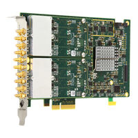
Spectrum M2P.5926-X4 Hardware Manual (190 pages)
Fast 16 bit transient recorder, digitizer, A/D converter board for PCI Express bus
Brand:
Spectrum
| Category:
Measuring Instruments
| Size: 12 MB
Table of Contents
Table of Contents
3
Safety Instructions
8
Symbols and Safety Labels
8
General Safety Information
8
Requirements for Users and Duties for Operators
8
General Safety at Work
8
Table 1: Symbols and Safety Labels
8
Bringing the Product into Service
9
Intended Use
9
Application Area of the Product
9
Requirements for the Technical State of the Product
9
Requirements for Operation
9
Electrical Safety and Power Supply
9
Requirements for the Location
9
Requirements on the Ventilation
9
Maintenance
9
Repair/Service
10
Cleaning the Module Housing (NETBOX Devices, Cables, Amplfiers, Systems Only)
10
Opening the Module (NETBOX Devices, Amplifiers Only)
10
Dismounting Parts of the Card (Instrument Card Only)
10
Markings and Labelling
10
Packing List
11
Table 2: Packing List
11
Introduction
12
Preface
12
Overview
12
M2P Cards for PCI Express (Pcie)
12
General Information
12
Different Models of the M2P.59Xx Series
13
Image 1: M2P Card and Front Panel for Versions with One Differential Channel
13
Image 2: M2P Card and Front Panel for Versions with Two Differential Channels
13
Image 3: M2P Card and Front Panel for Versions with Two Differential Channels / Four Single-Ended Channels
13
Image 4: M2P Card and Front Panel for Versions with Four Differential Channels
14
Image 5: M2P Card and Front Panel for Versions with Four Differential Channels / Eight Single-Ended Channels
14
Additional Options
15
Digital I/O with Dig-SMB
15
Digital I/O with Dig-FX2
15
Image 6: M2P Card with Installed Digsmb Digital Option Showing the 16 SMB Connectors
15
Image 7: M2P Card with Installed Digfx2 Digital Option Showing Connectors and Jumper Locations for Connection Switching
15
Star-Hub
16
Image 8: M2P Card with Installed Star-Hub 16 in the Extension Version
16
The Spectrum Type Plate
17
Table 3: M2P Card Backside with the Spectrum Type Plate and Information
17
Hardware Information
18
Block Diagrams
18
Image 9: Block Diagram of M2P.59Xx Showing the Analog Module (Green) and the Components of the Base Card. the Optional Star-Hub Is
18
Technical Data
19
Order Information
25
M2P Order Information
25
Hardware Installation
27
ESD Precautions
27
Sources of Noise
27
Cooling Precautions
27
Connector Handling Precautions
27
M2P Pcie Cards
28
System Requirements
28
Installing the M2P Board in the System
28
Additional Notes on the M2P Cards Pcie X16 Slot Retention
28
Image 10: Installing M2P Card into the Slot
28
Image 11: Location of the M2P Pcie Retention Hook
28
Additional Notes for M2P Main Cards with Heat-Sink Requiring Two Slots
29
Installing a Board with Digital Inputs/Outputs Mounted on an Extra Bracket
29
Image 12: Installation of a M2P Card with Installed Digital Option in the Pcie Slot
29
Installing Multiple Boards Synchronized by Star-Hub Option
30
Image 13: Installation of M2P Star-Hub Synchronization Cables
30
Image 14: Star-Hub Connector Pin-1 Marker
30
Software Driver Installation
31
Windows
31
Before Installation
31
Running the Driver Installer
31
Image 15: Windows Device Manager Showing a New Spectrum Card
31
Image 16: Spectrum Driver Installer Welcome Screen
31
After Installation
32
Image 17: Spectrum Driver Installer - Progress
32
Image 18: Spectrum Driver Installer - Finished
32
Image 19: Windows Device Manager Showing Properly Installed Spectrum Card
32
Linux
33
Overview
33
Standard Driver Installation
33
Standard Driver Update
34
Compilation of Kernel Driver Sources (Optional and Local Cards Only)
34
Update of a Self Compiled Kernel Driver
34
Installing the Library Only Without a Kernel (for Remote Devices)
35
Control Center
35
Image 20: Device Manager Showing a New Spectrum Card
35
Software
37
Software Overview
37
Card Control Center
37
Image 21: Spectrum Kernel Driver, API Library and Software Structure
37
Image 22: Spectrum Control Center Installer
37
Discovery of Remote Cards, Digitizernetbox/Generatornetbox/Hybridnetbox Products
38
Wake on LAN of Digitizernetbox/Generatornetbox/Hybridnetbox
38
Image 23: Spectrum Control Center Showing Detail Card Information
38
Image 24: Spectrum Control Center - Entering an IP Address for a NETBOX
38
Image 25: Spectrum Control Center: Wake on LAN for a Cached Card
38
Netbox Monitor
39
Device Identification
39
Image 26: Netbox Monitor Activation
39
Hardware Information
40
Firmware Information
40
Image 27: Spectrum Control Center: Detailed Hardware Information on Installed Card
40
Image 28: Spectrum Control Center - Showing Firmware Information of an Installed Card
40
Software License Information
41
Driver Information
41
Image 29: Spectrum Control Center - Showing Firmware Information of an Installed Card
41
Image 30: Spectrum Control Center - Showing Driver Information Details
41
Installing and Removing Demo Cards
42
Feature Upgrade
42
Software License Upgrade
42
Performing Card Calibration
42
Image 31: Spectrum Control Center - Adding a Demo Card to the Sysstem
42
Image 32: Spectrum Control Center - Feature Update, Code Entry
42
Image 33: Spectrum Control Center - Software License Installe
42
Image 34: Spectrum Control Center - Running an On-Board Calibration
42
Performing Memory Test
43
Transfer Speed Test
43
Debug Logging for Support Cases
43
Image 35: Spectrum Control Center - Performing Memory Test
43
Image 36: Spectrum Control Center - Running a Transfer Speed Test of One Card
43
Image 37: Spectrum Control Center - Activate Debug Logging for Support Cases
43
Device Mapping
44
Firmware Upgrade
44
Image 38: Spectrum Control Center - Using Device Mapping
44
Image 39: Spectrum Control Center - Doing a Firmware Update for One Device
44
Accessing the Hardware with Sbench 6
45
C/C++ Driver Interface
45
Header Files
45
Image 40: Sbench 6 Overview of Main Functionality with Demo Data
45
Table 4: List of C/C++ Header Files in Driver
45
General Information on Windows 64 Bit Drivers
46
Microsoft Visual C++ 6.0, 2005 and Newer 32 Bit
46
Microsoft Visual C++ 2005 and Newer 64 Bit
46
C++ Builder 32 Bit
46
Linux Gnu C/C++ 32/64 Bit
47
C++ for .NET
47
Other Windows C/C++ Compilers 32 Bit
47
Other Windows C/C++ Compilers 64 Bit
47
Driver Functions
47
Table 5: C/C++ Type Declarations for Drivers and Examples
48
Table 6: C/C++ Type Naming Convention Throughout Drivers and Examples
48
Table 7: Spectrum Driver API Functions Overview and Differentiation between 32 Bit and 64 Bit Registers
50
Delphi (Pascal) Programming Interface
53
Driver Interface
53
Image 41: Structure of the Delphi Exmaples
53
Examples
54
NET Programming Languages
55
Library
55
Declaration
55
Using C
55
Using Managed C++/CLI
56
Using VB.NET
56
Using J
56
Python Programming Interface and Examples
57
Driver Interface
57
Examples
58
Java Programming Interface and Examples
59
Driver Interface
59
Examples
59
Julia Programming Interface and Examples
60
Driver Interface
60
Examples
60
Labview Driver and Examples
61
MATLAB Driver and Examples
61
SCAPP - CUDA GPU Based Data Processing
61
Image 42: Labview Driver Oscilloscope Example
61
Image 43: Spectrum MATLAB Driver Structure
61
Image 44: GPU Usage with SCAPP SDK: Data Transfer Options
61
Programming the Board
62
Overview
62
Register Tables
62
Programming Examples
62
Table 8: Spectrum API: Command Register and Basic Commands
62
Initialization
63
Initialization of Remote Products
63
Error Handling
63
Gathering Information from the Card
64
Card Type
65
Table 9: Spectrum API: Card Type Register
65
Hardware and PCB Version
66
Firmware Versions
66
Table 11: Spectrum API: Register for Hardware and PCB Versions of Standard Card
66
Table 12: Spectrum API: Registers of Hardware and PCB Version of Optional Extension Card
66
Table 13: Spectrum API: Registers of Hardware and PCB Version of Optional Digital Extension Module
66
Production Date
67
Last Calibration Date (Analog Cards Only)
67
Table 14: Spectrum API: Register Overview of Firmware Versions
67
Table 15: Spectrum API: Register Overview of Reading Current Firmware
67
Serial Number
68
Maximum Possible Sampling Rate
68
Installed Memory
68
Installed Features and Options
68
Table 16: Spectrum API: Feature Register and Available Feature Flags
68
Miscellaneous Card Information
69
Function Type of the Card
69
Table 17: Spectrum API: Extended Feature Register and Available Extended Feature Flags
69
Table 18: Spectrum API: Register Overview of Miscellaneous Cards Information
69
Table 19: Spectrum API: Register Card Function Type and Possible Types
69
Used Type of Driver
70
Custom Modifications
70
Table 20: Spectrum API: Register Driver Type Information and Possible Driver Types
70
Table 21: Spectrum API: Custom Modification Register and Different Bitmasks to Split the Register in Various Hardware Parts
70
Reset
71
Table 22: Spectrum API: Command Register and Reset Command
71
Analog Inputs
72
Channel Selection
72
Single-Ended Inputs
72
Table 23: Spectrum API: Channel Enable Register: Used to Select the Channels for the Next Acquisition/Generation
72
Differential Inputs
73
Image 45: Levels of Differential Signals in Comparison to Single-Ended Signals
73
Mixed Single-Ended and Differential Inputs
74
Important Note on Channel Selection
74
Table 24: Spectrum API: Registers for Differential Mode Setup, Card with Multiplexed Channels (One Differential or Two Single-Ended)
74
Table 25: Spectrum API: Registers for Differential Mode Setup, Card with Multiplexed Channels (One Differential or One Single-Ended)
74
Setting up the Inputs
75
Input Ranges
75
Table 26: Spectrum API: Input Range Register and Available Input Range Settings
75
Table 27: Spectrum API: Registers to Read the Input Ranges
75
Input Offset
76
Image 46: Spectrum API: Using the Input Offset Shifting to Optimize the Usage of the Input Range
76
Image 47: Spectrum API: Effects of Different Input Offset Setting
76
Table 28: Spectrum API: Input Offset Registers
76
Table 29: Spectrum API: Registers to Read out the Possible Input Offset Settings Range
76
Input Termination
77
M2P.591X Digital Bandwidth Filter
77
Automatic On-Board Calibration of the Offset and Gain Settings
77
Table 30: Spectrum API: Register Table for Input Termination Settings
77
Read out of Input Features
78
Table 31: Spectrum API: Loading and Storing Calibration Values to the EEPROM
78
Table 32: Spectrum API: Readout Register for Analog Input Features with List of All Possible Input Features
78
Acquisition Modes
79
Overview
79
Setup of the Mode
79
Table 33: Spectrum API: Card Mode and Read out of Available Card Mode Software Registers
79
Table 34: Spectrum API: Possible Values for the Card Mode Register. Description of the Different Card Modes
79
Commands
80
Table 35: Spectrum API: Card Command Register and Different Commands with Descriptions
80
Card Status
81
Acquisition Cards Status Overview
81
Generation Card Status Overview
81
Image 48: Acquisition Cards: Graphical Overview of Acquisition Status and Card Command Interaction
81
Table 36: Spectrum API: Card Status Register and Possible Status Values with Descriptions of the Status
81
Data Transfer
82
Image 49: Generation Cards: Graphical Overview of Generation Status and Card Command Interaction
82
Table 37: Spectrum API: Command Register and Commands for DMA Transfers
83
Table 38: Spectrum API: Status Register and Status Codes for DMA Data Transfer
83
Standard Single Acquisition Mode
84
Card Mode
84
Memory, Pre- and Posttrigger
84
Image 51: Standard Acquisition Mode and Pretrigger/Posttrigger/Trigger Relation
84
Example
85
FIFO Single Acquisition Mode
85
Card Mode
85
Length and Pretrigger
85
Difference to Standard Single Acquisition Mode
85
Example FIFO Acquisition
86
Limits of Pre Trigger, Post Trigger, Memory Size
86
Table 39: Overview of All Limits of Pre-Trigger, Post-Trigger and Memory Size for the Different Channel Activations and Acquisition Modes
86
Buffer Handling
87
Image 52: Overview of Buffer Handling for DMA Transfers Showing and the Interaction with the DMA Engine
87
Table 40: Spectrum API: Registers for DMA Buffer Handling
88
Table 41: Spectrum API: Content of DMA Buffer Handling Registers for Different Use Cases
88
Data Organization
91
Sample Format
91
Table 42: Spectrum API: Overview of Data Organization in Memory for Different Channel Configurations
91
Table 43: Spectrum API: Data Organization for Different Digital Input Option Configurations
91
Converting ADC Samples to Voltage Values
92
Clock Generation
93
Overview
93
Clock Mode Register
93
The Different Clock Modes
93
Standard Internal Sampling Clock (PLL)
93
Image 53: Overview of M2P Clock Structure with Optional Star-Hub
93
Table 44: Spectrum API: Clock Mode Register and Available Clock Modes
93
Table 45: Spectrum API: Clock Mode Software Register and Setting
93
Maximum and Minimum Internal Sampling Rate
94
Oversampling
94
Direct External Clock
94
Table 46: Spectrum API: Samplerate Software Reguster
94
Table 47: Spectrum API: Clock Output and Clock Output Frequency Register
94
Table 48: Spectrum API: Software Clock Mode Register and External Clock Settings
94
External Reference Clock
95
Table 49: Spectrum API: Clock Termination Software Register
95
Table 50: Spectrum API: Clock Threshold Software Registers and Available Range Therefore
95
Table 51: Spectrum API: Clock Mode Software Register and External Reference Clock
95
Table 52: Spectrum API: Reference Clock Software Register
95
Table 53: Spectrum API: Clock Threshold Software Registers and Available Range Therefore
96
Trigger Modes and Appendant Registers
97
General Description
97
Trigger Engine Overview
97
Image 54: M2P Card Trigger Engine Overview with the Different Trigger Sources and Trigger Outputs
97
Trigger Masks
98
Trigger or Mask
98
Image 55: Trigger Overview - Trigger or Mask
98
Image 56: Trigger or Mask Details
98
Table 54: Spectrum API: External Trigger or Mask Related Software Register and Available Settings
98
Trigger and Mask
99
Image 57: Trigger Overview - Trigger and Mask
99
Image 59: Trigger and Mask Details
99
Table 55: Spectrum API: Channel Trigger or Mask Related Software Register and Available Settings
99
Software Trigger
100
Table 56: Spectrum API: External Trigger and Mask Related Software Register and Available Settings
100
Table 57: Spectrum API: Channel Trigger and Mask Related Software Register and Available Settings
100
Table 58: Spectrum API: Software Register and Register Setting for Software Trigger
100
Force- and Enable Trigger
101
Trigger Delay
101
Image 60: M2P Trigger Engine Overview and Delay Trigger
101
Table 59: Spectrum API: Command Register and Force Trigger Command
101
Table 60: Spectrum API: Command Register and Trigger Enable/Disable Command
101
Table 61: Spectrum API: Delay Trigger Software Registers and Programmable Settings
101
Trigger Holdoff
102
Main Analog External Trigger (Ext0)
102
Image 61: Trigger Engine Overview and External Trigger
102
Table 62: Spectrum API: Trigger Holdoff Related Registers and Settings for These
102
Trigger Mode
103
Trigger Input Termination
103
Trigger Level
103
Detailed Description of the External Analog Trigger Modes
103
Table 63: Spectrum API: External Trigger Mode Registers and Available Settings Therefore
103
Table 64: Spectrum API: Trigger or Mask and Setup for External Trigger
103
Table 65: Spectrum API: Software Registers for External Trigger Levels
103
Table 66: Spectrum API: Software Registers to Program External Trigger
103
External Logic Trigger (X1, X2, X3)
108
Trigger Mode
108
Image 62: Trigger Engine Overview and Multi Purpose Trigger
108
Table 67: Spectrum API: External Logic Trigger Registers and Settings for Them
108
Table 68: Spectrum API: Trigger or Mask Register an Settings for External Logic Trigger
108
Detailed Description of the Logic Trigger Modes
109
Channel Trigger
112
Overview of the Channel Trigger Registers
112
Image 63: Trigger Engine Overview and Channel Trigger
112
Table 69: Spectrum API: Channel Trigger Register and Available Settings for These
112
Channel Trigger Level
113
Table 70: Spectrum API: Channel Trigger Level Registers
113
Table 71: Spectrum API: Standard Input Ranges and Representation of Trigger Level Settings in Voltage
114
Detailed Description of the Channel Trigger Modes
115
Multi Purpose I/O Lines
123
On-Board I/O Lines (X0, X1, X2, X3)
123
Programming the Behavior
123
Image 64: Overview Block Diagram of Multi-Purpose I/O Lines
123
Table 72: Spectrum API: XIO Lines and Mode Software Registers with Their Available Settings
123
Asynchronous I/O
124
Special Behavior of Trigger Output
124
Synchronous Digital Inputs
125
Table 73: Spectrum API: Digital Input Options Registers
125
Table 74: Spectrum API: Data Organization for Different Digital Input Option Configurations
125
Additional I/O Lines with Option -Digsmb and -Digfx2
127
Programming the Behavior
127
Table 75: Spectrum API: Mode Registers for XIO Lines on Additional Digital I/O Module and Their Settings
127
Asynchronous I/O
128
Synchronous Digital Inputs
128
Table 76: Spectrum API: Registers for Synchronous Digital Inputs
128
Table 77: Spectrum API: Data Organization for Different Digital Input Option Configurations
129
Table 78: Sample Format of Analog Samples in Combination with Digital Input Channels
130
Mode Multiple Recording
131
Recording Modes
131
Standard Mode
131
FIFO Mode
131
Image 65: Drawing of Multiple Recording Acquisition
131
Table 79: Spectrum API: Software Registers for Multiple Recording Mode Setup
131
Limits of Pre Trigger, Post Trigger, Memory Size
132
Multiple Recording and Timestamps
133
Trigger Modes
133
Trigger Counter
133
Image 66: Drawing of Multiple Recording Acquisition with Timestamps
133
Programming Examples
134
Mode Gated Sampling
135
Acquisition Modes
135
Standard Mode
135
FIFO Mode
135
Image 67: Drawing of Gated Sampling Mode
135
Table 81: Spectrum API: Registers and Settings for Gated Sampling Mode
135
Limits of Pre Trigger, Post Trigger, Memory Size
136
Gate-End Alignment
137
Gated Sampling and Timestamps
137
Image 68: Drawing of Gated Sampling Mode and Timestamp Positions
137
Table 83: Spectrum API: Gate End Alignement in Gated Sampling Mode
137
Trigger
138
Detailed Description of the External Analog Trigger Modes
138
Table 84: Spectrum API: External Analog Trigger Registers
138
Detailed Description of the Logic Gate Trigger Modes
140
Channel Triggers Modes
142
Programming Examples
148
ABA Mode (Dual Timebase)
149
General Information
149
Standard Mode
149
Image 69: Drawing of ABA Mode Usage and Sampling Rate Differences
149
Table 85: Spectrum API: ABA Settings Restigerts
149
FIFO Mode
150
Limits of Pre Trigger, Post Trigger, Memory Size
150
Example for Setting ABA Mode
151
Reading out ABA Data
152
General
152
Data Transfer Using DMA
152
Image 70: Overview of Acquisition Data, ABA Data and Timestamp Data DMA Transfer
152
Table 87: Spectrum API: Extra DMA Commands (ABA and Timestamp)
152
Table 88: Spectrum APUI: Extra DMA Status (ABA and Timestamp)
152
Table 89: Spectrum API: ABA and Timestamp DMA Buffer Handling Registers
153
Data Transfer Using Polling
154
Comparison of DMA and Polling Commands
155
ABA Mode and Timestamps
155
Image 71: Drawing of ABA Mode
155
Table 90: Spectrum API: Timestamp Command Register and ABA Mode Settings
155
Timestamps
157
General Information
157
Table 91: Spectrum API: Timestamp Related Register and Available Timestamp Commands
157
Example for Setting Timestamp Mode
158
Timestamp Modes
158
Standard Mode
158
Startreset Mode
158
Image 72: Drawing of Timestamp Acquisition in Standard Mode in Relation to Card Start and Trigger Detection
158
Image 73: Drawing of Timestamp Acquisition in Start-Reset Mode in Relation to Card Start and Trigger Detection
158
Table 92: Spectrum AP: Timestamp Commands for Standard Mode
158
Refclock Mode
159
Image 74: Drawing of Timestamp Acquisition in Refclock Mode in Relation to Card Start and Trigger Detection
159
Table 93: Spectrum API: Timestamp Commands for Star-Reset Mode
159
Table 94: Spectrum API: Timestamp Commands for Refclock Mode
159
Reading out the Timestamps
160
General
160
Image 75: Overview of Acquisition Data, ABA Data and Timestamp Data DMA Transfer
160
Table 95: Spectrum API: Extra DMA Commands (ABA and Timestamp)
160
Data Transfer Using DMA
161
Table 96: Spectrum APUI: Extra DMA Status (ABA and Timestamp)
161
Table 97: Spectrum API: ABA and Timestamp DMA Buffer Handling Registers
161
Data Transfer Using Polling
162
Comparison of DMA and Polling Commands
163
Data Format
163
Combination of Memory Segmentation Options with Timestamps
165
Multiple Recording and Timestamps
165
Gate-End Alignment
165
Image 76: Drawing of Multiple Recording Acquisition with Timestamps
165
Table 98: Spectrum API: Gate End Alignement in Gated Sampling Mode
165
Gated Sampling and Timestamps
166
Image 77: Drawing of Gated Sampling Mode and Timestamp Positions
166
ABA Mode and Timestamps
167
Image 78: Drawing of ABA Mode
167
Table 99: Spectrum API: Timestamp Command Register and ABA Mode Settings
167
Option Star-Hub
168
Star-Hub Introduction
168
Star-Hub Trigger Engine
168
Star-Hub Clock Engine
168
Software Interface
168
Star-Hub Initialization
168
Image 79: Drawing of Star-Hub Clock Engine Location and Interaction with Card Clock
168
Table 100: Spectrum API: Star-Hub Related Registers for Reading Detected Connections
169
Setup of Synchronization
170
Limits of Clock for Synchronized Cards
171
Setup of Trigger
171
Run the Synchronized Cards
172
Error Handling
172
Table 101: Spectrum API: Star-Hub Synchronization Commands
172
Option Remote Server
173
Introduction
173
Installing and Starting the Remote Server
173
Windows
173
Linux
173
Detecting the Digitizernetbox/Generatornetbox/Hybridnetbox
173
Discovery Function
173
Image 80: Overview of Remote Server Option Interaction in Comparison to NETBOX Devices
173
Finding the Digitizernetbox/Generatornetbox/Hybridnetbox in the Network
174
Image 81: Windows Screenshot: Finding a Remote Spectrum Device Like Digitizernetbox
174
Troubleshooting
175
Accessing Remote Cards
175
Appendix
176
Error Codes
176
Table 102: Spectrum API: Driver Error Codes and Error Description
176
Spectrum Knowledge Base
177
Pin Assignment of the Multipin Connector
178
Option "Digital I/O Dig-FX2
178
Pin Assignment of the Multipin Cable
178
Image 82: the Standard 40-Pole Flat Ribbon Cable Used Tor Digital Connection
178
Image 83: Location of Pin1 on the Standard 40-Pole Flat Ribbon Cable
178
IDC Footprints
179
Image 84: IDC Connector Pinning of Standard Digital Connection
179
Image 85: IDC Connector Marking of Pin 1
179
Table 103: Digital Connector and Cable: Relation between the Card Connector Pin and the IDC Pin and the Signal
179
Details on M2P Cards I/O Lines
180
Multi Purpose I/O Lines
180
Additional I/O Lines (Option -Digfx2)
180
Image 86: Electrical Connection and Termination of Multi-Purpose I/O Lines
180
Image 87: Electrical Connection of Additional I/O Lines on Connection Digfx2
180
Additional I/O Lines (Option -Digsmb)
181
Additional I/O Lines (Option -Digbnc)
181
Interfacing M2P Clock In/Out with M4I/M4X
181
Image 88: Electrical Connection of Additional I/O Lines on Connection Digsmb
181
Image 89: Electrical Connection of Additional I/O Lines on Connection Digbnc (Digitizernetbox)
181
Image 90: Electrical Interfacing of Clock Connections between M2P and M4I Cards
181
Temperature Sensors
183
Temperature Read-Out Registers
183
Temperature Hints
183
59Xx Temperatures and Limits
183
Table 104: Spectrum API: Temperature Sensor Registers
183
Table 105: 59Xx Card Typical Temperatures and Limits
183
Details on M2P Cards Status LED
184
Turning on Card Identification LED
184
Table 106: Color Coding of the Status LED
184
Abbreviations
185
Table 107: Abbreviations Used Throughout the Spectrum Documents
185
List of Figures
186
List of Tables
188
Advertisement
Advertisement
Related Products
Spectrum M2p.59 Series
Spectrum M2P.5941-X4
Spectrum M2P.5931-X4
Spectrum M2P.5936-X4
Spectrum M2P.5966-X4
Spectrum M2P.5962-X4
Spectrum M2P.5961-X4
Spectrum M2i.3022
Spectrum M2i.3022-exp
Spectrum M2i.3027-exp
Spectrum Categories
Indoor Furnishing
Plumbing Product
Measuring Instruments
Receiver
Remote Control
More Spectrum Manuals
Login
Sign In
OR
Sign in with Facebook
Sign in with Google
Upload manual
Upload from disk
Upload from URL