Advertisement
Advertisement
Table of Contents

Subscribe to Our Youtube Channel
Related Manuals for Rain i-dial


Summary of Contents for Rain i-dial
- Page 1 EN. INSTRUCTIONS N N O V A T I V E I R R I G A T I O N S Y S T E M S...
- Page 2 RAIN s.p.a. via Kennedy 38/40 20023 Cerro Maggiore ITALY (MI) DESCRIPTION INDICE The new controller I-DIAL, available in indoor and outdoor version 4-6-8 stations, Pag. 17 is ideal for all residential applications and TECHNICAL FEATURES follows the philosophy to simplicity of programming in 3 RAIN steps: start time, Pag.
- Page 3 • Buffer batteries 2 x 1.5 volt AA alkaline (not • Buffer batteries 2 x 1.5 volt AA alkaline (not included) included) • Output rain sensor programmable per station • Output rain sensor programmable per station • Function OFF • Function OFF •...
- Page 4 • Buffer batteries 2 x 1.5 volt AA alkaline (not • Buffer batteries 2 x 1.5 volt AA alkaline (not included) included) • Output rain sensor programmable per station • Output rain sensor programmable per station • Function OFF • Function OFF •...
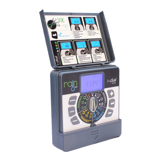
- Page 5 THE CONTROLLER indoor 1 2 3 model NEXT START PROG FERTILIZER RAIN DELAY START TIME EVERY DURATION ZONE HOURS outdoor model c c m 1 2 3 4 5 6 7 8 24 vac sensor WARNING The version with the outside transformer...
- Page 6 (budget) Wiring Compartment Giorno 24 vac Cables transformer Input Indica il tempo d’irrigazione sensor Rain sensor input Giorni della settimana Pump control or master valve Output Indica l’intervallo d’irrigazione 1...8 Sector output Indica l’irrigazione manuale in corso The button CLEAR eliminates programming...
-
Page 7: Electrical Connections
ELECTRICAL CONNECTIONS Elettrovalvola zona 1 Elettrovalvola zona 2 Elettrovalvola zona 3 Cavo 24 vac Elettrovalvola zona 4 Filo comune Cavo sensore Each 24 VAC electric valve is equipped with two black cables. The fi rst one identifi es the number of the area and it will be connected to one of the outputs numbered in the terminal compartment and the second one is the common cable that will be connected to the Exit C in the terminal compart- ment along with all common cables of all electric valves. - Page 8 going to the timer. The other valve wire is to be WIRING THE ELECTRIC VALVES connected to the specifi c station wire that will control that valve • All wires should be joined together using wire nuts, solder, or vinyl tape. For additional protec- tion to waterproof connections a WaterMaster®...
-
Page 9: Connecting The Transformer
• Connect the common wire to the terminal labeled “com” CONNECTING THE TRANSFORMER • A rain sensor or other type of micro-switch weather sensor may be connected to the controller. The purpose of the sensor is to stop watering when precipitation is suffi... -
Page 10: Installing The Batteries
INSTALLING THE BATTERIES CURRENT TIME AND DAY SETTING TIME Remove the battery compart- ment by unscrewing the two screws on the edges. Put two AA (1.5 V) alkaline batteries in the compartment. Replace the battery compart- ment in its place and screw. - Page 11 IRRIGATION PLANNING Step 2: Duration setting for each zones (duration zone) The controller I-Dial is equipped with 4 programs (A, B, C, D) completely independent and programmable by following three simple steps. Each program allows a daily start and can be combined PROG with one or more electric valves.
-
Page 12: Manual Start
Step 3: watering days setting MANUAL START (watering days) Pressing the MANUAL button you can irrigate without start time setting. This allows you to try the system and I this section it will be possible to choose watering days its functionality or run an extra irrigation in hot days. through the selection of the days of the week or throu- gh an interval irrigation. - Page 13 ADDITIONAL FEATURES - BUDGET The function BUDGET allows to modify simultaneously all irrigation times in percentage. You can change the ZONE percentage from a minimum of 10% to a maximum of 200%. EXAMPLE: the controller is programmed to per- manual form a watering cycle at 07:00 AM with irrigation zone times of 10 minutes per zone.
- Page 14 Pump and function SEnS. In these two functions you can set the start of the pump or turn on/off the sensor rain for single zone. EXAMPLE: The garden is composed of four areas here: 3 zones for watering of the lawn with sprinklers connected to a pump and one area for watering of fl...
-
Page 15: Problem Solving
The rain sensor • Rain sensor defective • Verify the operation of the does not stop the • Stations have been program- rain sensor and correct cabling system med to keep out the sensor system cablatura dell’impianto • Program again the exclusion... - Page 16 (requiring proof of purchase). We reserve the right to inspect the defective part before replacing it. RAIN spa will not be responsible for any costs or accessories or consequential damages, caused by a defect of the product. The responsibility of RAIN spa under this warranty is limited only to the replacement of defective components.
Need help?
Do you have a question about the i-dial and is the answer not in the manual?
Questions and answers