Advertisement
Advertisement
Table of Contents

Related Manuals for Lithium Grim Dumbl'Ador


Summary of Contents for Lithium Grim Dumbl'Ador
- Page 1 Dumbl’Ador Building instructions V1.0...
-
Page 2: Table Of Contents
Dumbl’Ador v1.0 Table of contents Components ............................3 PCB layout ............................... 3 Building sequence ........................... 4 Off board wiring ............................5 Troubleshooting ............................6 Schematic ..............................7 Read this entire manual thoroughly before you start building the effect! Especially the modification part. -
Page 3: Components
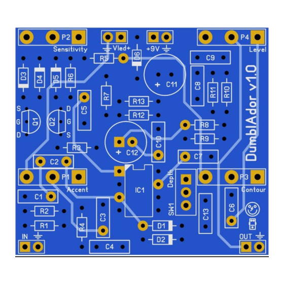
Dumbl’Ador v1.0 Components Name Value Comment Name Value Comment SMF/MKT/Wima P1 B10k Accent SMF/MKT/Wima P2 Sensitivity 220n SMF/MKT/Wima P3 B50k Contour SMF/MKT/Wima P4 A100k Level SMF/MKT/Wima Q1 2N7000 SMF/MKT/Wima Q2 2N7000 100n SMF/MKT/Wima R1 1% metalfilm SMF/MKT/Wima R2 1% metalfilm 100n SMF/MKT/Wima R3 470k... -
Page 4: Building Sequence
Dumbl’Ador v1.0 Building sequence Soldering this board can be very complicated for some people since the solder pads are very close together. Use a magnifying glass to make the job easier. Do not blow on your solder in an attempt to cool it down. That will possibly result in a bad join that might corrode! If you want to experiment with other diodes or transistors then you could socket them instead of soldering them to the board. -
Page 5: Off Board Wiring
Dumbl’Ador v1.0 Off board wiring The biggest challenge of this build is to get all the offboard wiring correct and fit it in a box. Take your time measuring and testing before you start fitting everything in the box. P1-P4 are PCB mounted potentiometers (Alpha). The rectangle pad marks pin 1 of a potentiometer. The images below show how you can recognize which pin is which on a potentiometer. -
Page 6: Troubleshooting
Dumbl’Ador v1.0 Troubleshooting All PCB’s have been 100% factory e-tested and out of every batch I receive I build an effect to double check, so there should not be a connection problem on the PCB itself. The board is not working (at all), what now? •... -
Page 7: Schematic
Dumbl’Ador v1.0 Schematic Manufacturer and product names are mentioned solely for circuit identification, and where applicable their trademarks are the property of their respective owners who are in no way associated or affiliated with the author. No cooperation or endorsement is implied.
Need help?
Do you have a question about the Dumbl'Ador and is the answer not in the manual?
Questions and answers