Table of Contents
Advertisement
Quick Links
Advertisement
Table of Contents

Related Manuals for Delta PCS100HV


Summary of Contents for Delta PCS100HV
- Page 1 Delta Power Conditioning System (PCS100HV) Installation Manual Version: 1.0.4...
-
Page 2: Table Of Contents
Features Applications Accessories Installation Before You Begin Foundation Location and Ventilation Requirements Unpacking the 1-Unit PCS100HV Unpacking the 2-Unit PCS100HV Installing the PCS Onsite Securing a Cabinet in a Final Location Wiring Instructions Safety Wire Sizing and Ratings Preparation of Cables... - Page 3 Glossary Screw Torque Table Installation Manual...
- Page 4 FIGURE 5. FRONT AND SIDE VIEWS OF A DELTA PCS100HV · · · · · · · · · · · · · · · · · · · · · · · · · · · · · · ·...
- Page 5 TABLE 16: TERMINAL RESISTORS SWITCHES SETTING OF SINGLE PCS FOR ETHERNET COMMUNICATION ....... 38 TABLE 17: TERMINAL RESISTORS SWITCHES SETTING OF PARALLEL PCS FOR ETHERNET COMMUNICATION ....38 TABLE 18: TECHNICAL SPECIFICATIONS OF THE DELTA PCS100HV ..................46 TABLE 19: ICC DECLARATION (R.M.S. VALUE, ICP,MR, DEVICE) ..................47 TABLE 20: SCREW TORQUE TABLE FOR M3~M5 SCREWS....................
- Page 6 Delta may modify or update the Manual from time to time without any notice. Delta will do its best to keep the Manual updated and maintain the accuracy of the Manual. Delta disclaims any kinds or forms of warranty, guarantee, or undertaking, either explicitly or implicitly, including but not limited to the completeness, accuracy, non-infringement, merchantability, or fitness for particular purpose or usage.
-
Page 7: About This Manual
1. add noise symbol and instruction in page4 2. add prevent flood safety instruction in page4 3. add M12 expansion bolts (not provided with PCS100HV) note in page8 4. change voltage rating of IO wire from 600V to 300V, in page26 5. -
Page 8: Purpose
The manual provides safety guidelines, detailed planning and setup information, the standard procedure of installing the PCS. It does not provide details of batteries. Audience The manual is intended for anyone who needs to install Delta PCS100HV. Installers should be certificated technicians or electricians. Organization This manual is organized into the following chapters: ... -
Page 9: Safety Symbols And Terminologies
About this Manual Important Safety Instructions Save these Instructions General Safety Instructions (EN) This manual contains important instructions for PCS that should be followed during installation and maintenance. PCS is designed and tested to meet all applicable International safety standards. However, like all electrical and electronic equipment, safety precautions must be observed and followed during installation and operation of PCS to reduce the risk of personal injury and to ensure a safe installation. - Page 10 The PCS section does not contain user-serviceable parts. For all service and maintenance, a Delta repair technician or authorized service partner is required for onsite maintenance services. Read all of these instructions, cautions, and warnings for the PCS and associated PCS documentation.
-
Page 11: Introduction
EMS. With Delta’s PCS solution you can realize the fullest value of an energy storage system. Figure 1. System Architecture... -
Page 12: Features
PCS and local load with the grid when grid voltage or frequency abnormal. This external automatic disconnection device shall meet AS4777.2 requirements. And this external automatic disconnection device is not in Delta supply scope. Note:... -
Page 13: Accessories
Check that the following items are included. Contact your vendor if any item is missing or appear damaged. Figure 3. Accessories The key is tied to the hoisting ring. The connectors are connected to the corresponding terminals. All of the accessories are transported with the PCS100HV. Installation Manual... -
Page 14: Installation
Installation Installation This chapter describes how to mount and install the PCS, including the information about recommended tools, groundwork preparation, location and ventilation considerations, unpacking, moving, and mounting. Read this chapter and plan your PCS layout and installation accordingly. Before You Begin Recommended Tools The following tools are recommended for a successful installation: ... -
Page 15: Foundation
1. Mounting by the left and right sides of the unit base: Drill four holes for M12 expansion bolts (not provided with PCS100HV) at the 4 corners of an area of 537 x 300 mm as marked in number 1. -
Page 16: Location And Ventilation Requirements
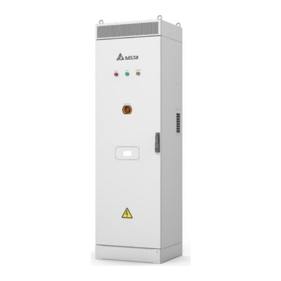
Location and Ventilation Requirements Dimensions 500 mm(19.68in) 600 mm(23.62in) Figure 5. Front and Side Views of a Delta PCS100HV Location Considerations To fully experience the benefits and reliability of the PCS design, follow the provided guidelines: The PCS unit is rated IP55 and configured for outdoor installations. - Page 17 Installation Under certain operating conditions, the PCS emits an audible noise. It is advisable to install away from living accommodations to protect against noise levels. The PCS should not be installed in an excessively dusty area, as this may decrease the performance of the air cooling system.
- Page 18 Installation Maintenance distance requirements A minimum distance behind the PCS is required for maintenance from the rear side as shown in figure 7. Item A:When the PCS fixing screws are installed in left and right, the left and right of PCS need at least 800mm installation space.
-
Page 19: Unpacking The 1-Unit Pcs100Hv
Figure 9. Removing All Walls of 1-Unit PCS100HV Upon unpacking the unit, inspect the unit for signs of damages that may have been caused during shipping. If any sign of damage is found, immediately contact Delta and the shipping company. Installation Manual... -
Page 20: Unpacking The 2-Unit Pcs100Hv
Figure 10. Removing All Walls 2-Unit PCS100HV Upon unpacking the unit, inspect the unit for any signs of damages that may have been caused during shipping. If any sign of damage is found, immediately contact Delta and the shipping company. -
Page 21: Installing The Pcs Onsite
Installation Installing the PCS Onsite Safety Considerations The following safety information is intended to reduce the risk of accidents: Keep the floor around the PCS clean to prevent metallic dust, iron, or other metal fillings from being drawn inside the device, consequently causing short circuits. Closed area installations: ... - Page 22 Installation AC and DC Disconnect Switch Concerns There are two disconnect switches inside the PCS100HV, one for AC side and another for DC side. 1. AC disconnect switch has a load-breaking capacity and can break under normal voltage and current.
- Page 23 Installation Figure 11. Eye Bolts Locations WARNING! Before proceeding with the normal operation of the hoist, the operator(s) must be trained in accordance with the hoist manufacturer's operation manual. Failure to read and comply with any of the instructions and limitations noted in this manual and the hoist manufacturer's manual can result in product failure, serious bodily injury or death, and/or property damage.
- Page 24 Installation Figure 12. Eye Bolts Lifting 5. Once the PCS is placed in its final installation site, secure the PCS to the site as described in “Securing a Cabinet in a Final Location” on page 28. 6. Remove the hoist. 7.
- Page 25 1. Unpack the PCS, see “Unpacking the Unit” on page 12. 2. Using the forklift to move the PCS. Removing the PCS100HV from the left/right side: a. Remove the hexagonal nuts and washers securing the cabinet to the pallet. Figure 13. Releasing a PCS from a Pallet b.
- Page 26 Installation Figure 14. Removing Left and Right Base Covers d. Align the forklift with the bottom channels on the cabinet, see the following image. e. Once aligned, insert the forks into the channels until they are completely through the opposite side of the insertion channels. WARNING! Take care the unit is balanced and no risk to prevent it fall.
- Page 27 Installation Figure 15. Lateral Handling of PCS Front/Rear Handling a. Remove the hexagonal nuts and washers. Figure 16. Releasing a PCS from a Pallet Installation Manual...
- Page 28 Installation b. Remove the screws securing the front/rear base covers. c. Remove the front and rear side panels. Figure 17. Removing Front/Rear Base Covers d. Align the forklift with the bottom channels on the cabinet, see the following image. e. Once aligned, insert the forks into the channels until they are completely through the opposite side of the insertion channels.
- Page 29 Installation WARNING! Take care the unit is balanced and no risk to prevent it fall. Carefully lift the cabinet. Figure 18. Front/rear Side Handling 3. Once the cabinet is secured to the location, install the top cover, see “Securing a Cabinet in a Final Location”...
-
Page 30: Securing A Cabinet In A Final Location
Installation Securing a Cabinet in a Final Location 1. First, insert a washer in the anchoring bolt followed by a nut. 2. Turn the nut until it is lowered in the bolt. Do not tighten at this time. All nuts must be inserted in their respective anchoring bolts. -
Page 31: Wiring Instructions
This label is installed on the outside of the door and should remain clearly visible. Ensure all sources of power are OFF or disconnected before servicing. The Delta PCS100HV contains electrical components carrying potentially lethal voltages and currents. Extreme caution should be exercised around the system, especially when the cabinet door is open once it's installed. -
Page 32: Wire Sizing And Ratings
Wiring Instructions Wire Sizing and Ratings AC Wire Sizing and Ratings Prepare all the AC power cables as per the following wiring specifications: Table 2: AC Wire Sizing and Ratings Cable Type Solid Copper Conductor Voltage Rating 600 Volts or greater Temperature 90°... -
Page 33: Preparation Of Cables
Wiring Instructions Table 4: Grounding Wire Sizing and Ratings (Continued) Cable Type Solid Copper Conductor Quantity Communication and I/O Wire Sizing and Ratings Here are the requirements for the communication and I/O wires: Table 5: Communication and I/O Wire Sizing and Ratings Cable Type Solid Copper Conductor Voltage Rating... - Page 34 Wiring Instructions Preparing AC/DC Cables The following guidelines describe how to prepare the AC/DC cables for a grid or battery connection. When crimping a cable, a hexagonal crimping method is recommended. 1. Strip the head of the insulator of the AC and DC power cables. Insert the exposed part of the power cable into the junction hole of the corresponding cable lug.
-
Page 35: Communication And I/O Wiring And Terminal Resistor Setting
Wiring Instructions Communication and I/O Wiring and terminal resistor setting Get the wires with connectors or terminals prepared for communication and I/O connection through the front square hole of the unit base Plug these connectors into the relevant connector bases built-in at the inner left side wall of the cabinet adjacent to the DC terminals as the following figure: Figure 22. - Page 36 Wiring Instructions Table 6: Communication and I/O Connection Connector Description I/O terminal CNR6 16-pin connector Reserved for temperature sensor to MCU CNR1 10-pin connector For external grid or load current sensing CNR2 16-pin connector Black Start auxiliary power (24V) CNS8 2-pin connector Terminal resistor switches for RS485 and CAN SWR5...
- Page 37 Wiring Instructions I/O Connector (CNR6) The CNR6 connector is for digital I/O connection. Take out the green 16-pin connector (CNR6) from the accessory kit, and connect prepared AWG 16 wires to pin 1~16 of this connector as shown in figure 25. It’s recommended to substitute the wires with a multi-core shield cable.
- Page 38 Wiring Instructions 7. Digital Output 4-2 Dry Contact 4 (Max 24Vdc/10mA) 8. Digital Output 4-1 9. Digital Input 1-2 Wet Contact 1 (24Vdc/20mA) 10. Digital Input 1-1 11. Digital Input 2-2 Wet Contact 2 (24Vdc/20mA) 12. Digital Input 2-1 13. Digital Input 3-2 Wet Contact 3 (24Vdc/20mA) 14.
- Page 39 CNS8 2: GND DRM Connector (CNR7) PCS100HV supports all the demand response modes (DRMs) defined in the standard AS/NZS 4777.2. The CNR7 connector is an RJ45 socket that can be connected to a demand response enabling device (DRED). Installation Manual...
- Page 40 The CNR1 connector is reserved for battery temperature sensor. When the lead-acid batteries are connected to PCS100HV, the PIN1 and PIN2 of CNR1 can be connected to the battery temperature sensor. Take out the green 10-pin connector (CNR1 from the accessory kit, and connect two prepared AWG 16 wires to pin 1~2 of this connector as shown in the following figure.
- Page 41 Wiring Instructions Pin 1 Figure 29. CNR1 Pin Assignment Table 12: CNR1 Pin Assignment Notes Item Pin Assignment 1: Battery Temperature 1 Temperature sensor of lead-acid battery 2: Battery Temperature 2 CNR1 Reserved 3~10: NA Installation Manual...
- Page 42 Please be noted if one uses PC to connect with a PCS Ethernet port, there may be a connection issue due to the Ethernet Card compatibility in some PCs. In this case, we can suggest an Ethernet-USB converter to connect with PCS. PCS100HV Battery switche r...
- Page 43 Wiring Instructions Communication Connector (CNR3, CNR11) The CNR3 and CNR11 connectors are for communication with other PCS in parallel operation. Prepare two RJ45 connectors with shielded Ethernet cables, and the wires to the pin 1~8 of the RJ45 connector, and it should be connected as the graphic and pin assignment below: Figure 32.
- Page 44 Figure 34. SWR3, SWR5, SWS5 Assignment EMS Communication wiring The PCS100HV supports Ethernet for communication. Ethernet can be used for a site controller or EMS or remote server. A 120ohm terminal resistor must be set in the site controller before it’s connected.
- Page 45 Wiring Instructions Connected by Ethernet When a single PCS#1 is used, make sure the connector CNR11 is not connected. Ethernet Figure 35. Connected by Ethernet Terminal resistors setting The terminal resistor switches SWR3 and SWR5 must be set according to the following two tables. Table 16: Terminal resistors switches setting of single PCS for Ethernet communication Table 17: Terminal resistors switches setting of parallel PCS for Ethernet communication Installation Manual...
- Page 46 The PCS100HV can be connected to BMS by Ethernet or CAN. 1. If the PCS100HV is connected to BMS by Ethernet, a switcher should be used as shown in Fig.29. and the BMS communication wire, PCS communication wire and EMS connmunication wire should be connected to the same Ethernet switcher.
-
Page 47: Wiring
Wiring Instructions Wiring General Introduction For wiring convenience, you can make the cables and wires go from the left, right, front, or rear bottom side of the unit into the cabinet. The following sections will be described in the case of wiring from the front bottom side of the unit as an example. - Page 48 Wiring Instructions DC Wiring 1. Prepare DC cables: Prepare several 1/0 sizes, 1500V cables for DC wiring. The PCS supports up to 2 sets of battery connection, and each set of battery connection requires two cables (one for positive, the other for negative). Connect the DC cables to the two-hole lugs which are available, and use heat shrinkable tubing on the junction between the cables and lugs to prevent the exposure of the conductive part.
- Page 49 Wiring Instructions AC Wiring 1. Prepare AC cables: Prepare six 35 ~ 50 mm 600V cables for AC wiring. The PCS supports 3- phase/4-wire connection type AC wiring with L1, L2, and L3 phase and Neutral terminals, and each phase terminal requires two cables to connect. Attach the AC cables to the two-hole lugs, and use a thermal casing to prevent the exposure of the naked part.
- Page 50 Note: The grounding cable only needs a 35 ~ 50 mm cable. It’s recommended to connect the protection grounding wires of PCS100HV and battery cabinet to one bonding point and then grounding to the earth. Note: The grounding wire sizing must be larger than half of AC or DC wire sizing.
- Page 51 Warranty SPD tape As suggested by the device vendor, adhesive tape is used to fix the SPD module to SPD base support before shipping out of the factory. One needs to remove the adhesive tape on both SPDs. Be careful not to be scratched by the cover plate.
-
Page 52: Warranty
3. operated in unusual circumstances such as strikes, riots, wars, or nuclear disasters; 4. repaired, modified, moved, or installed by any party without Delta's prior written authorization; 5. damage due to accidents such as fire, inundation, unusual electric shock, power failure, or shipping;... -
Page 53: Appendix
Appendix Appendix Specifications Table 18: Technical Specifications of the Delta PCS100HV Item Description Grid-tied Operation Rated Grid Voltage 400 Vac (3P,N,PE) or (3P,PE) Grid Voltage Range 310 ~ 450 Vac Rated Grid Frequency 50 Hz Frequency Range 45~55 Hz Rated AC Power... - Page 54 Appendix IP Degree IP55 Interface & Communication Digital I/O 4 x Input, 3 x Output relays, 1 x REPO User Interface LED, EPO Emergency Stop Local EPO button & remote control Communication Ethernet/ Modbus TCP System Characteristic Peak Efficiency Standby Loss <25W @ sleep mode Dimensions (W x D x H) 600mm x 500 mm x 2000mm...
- Page 55 Appendix Glossary Abbreviation for “Alternating Current”. Abbreviation for “Authority Having Jurisdiction” (electrical inspector). American Wire Gauge. Basic Insulation Insulation to provide basic protection against electric shock. Battery management system. Abbreviation for “Direct Current”. The Electro-Magnetic Compatibility (EMC) concerns the technical of the mutual influencing of electrical devices through electromagnetic fields caused by them.
- Page 56 Appendix A local utility company is a company that distributes electricity over the grid. Power Conditioning System, an electrical device that converts DC direct voltage into AC voltage and/or direct current into alternating current. Power dissipation Power dissipation is designated as the difference between absorbed power and power of a device or process yielded.
- Page 57 Appendix Screw Torque Table 1. The torque level for M3~M5 screws is 4.8, refer to the following torque standard table to make sure the washers are in close contact with the screws. Table 20: Screw Torque Table for M3~M5 Screws Screw Assembly Torque Standard Unit: N·...
Need help?
Do you have a question about the PCS100HV and is the answer not in the manual?
Questions and answers