
Related Manuals for Delta 86HM050J245


Summary of Contents for Delta 86HM050J245
- Page 1 Inspire Ultra Inverter M16 86HM040J244 86HM050J245 INSTRUCTION MANUAL WARNING! Read and follow all safety precautions in Instruction Manual - improper use can cause serious injury. www.delta-dct.com...
-
Page 2: User Notice
This product must not be disposed together with the domestic waste. This product has to be disposed at an authorized place for recycling of electrical and electronic appliances. Thank you for purchasing Delta air conditioners. Before using, please read this manual carefully and keep it properly for further reference. -
Page 3: Table Of Contents
Contents 1 Safety Precautions ..................1 2 Installation Instructions ..................2 2.1 Installation Location and Matters Needing Attention ........ 2 2.2 Installation of the Outdoor Unit ..............4 2.3 Connection between Indoor and Outdoor Units ........7 2.4 Refrigerant Charging and Trial Running ..........9 3 Working Principles of the Unit ............... -
Page 4: Safety Precautions
1 Safety Precautions Please read this manual carefully before using and operating correctly as instructed in this manual. Please especially take notice of the following two symbols: Warning! It indicates improper operation which will lead to human casualty or severe injury. Caution! It indicates improper operation which will lead to injury or property damage. -
Page 5: Installation Instructions
The unit installed in the following places is likely to run abnormally. If unavoidable, please contact the professional personnel at the Delta appointed service center. ① where there is full of oil; ② alkaline soil off the sea; ③ where there is sulfur gas(like sulfur hot spring); ④ where there are devices with high frequency (like wireless devices, electric welding devices, or medical equipments);... - Page 6 Power Supply Air Switch (pieces× sectional area) 86HM040J244 208/230V~ 60Hz AWG12×3 86HM050J245 208/230V~ 60Hz AWG12×3 Notes: The specifications of the breaker and power cable listed in the table above are determined ① . based on the maximum power (maximum amps) of the unit.
-
Page 7: Installation Of The Outdoor Unit
86HM040J244 OUTDOOR UNIT INDOOR UNIT C INDOOR UNIT D INDOOR UNIT A 86HM050J245 OUTDOOR UNIT Fig.1 (5). Noise Precautions 1). The air conditioning unit should be installed where ventilation is in good condition, otherwise the working capability of the unit would be reduced or working noise would be increased. - Page 8 to let the unit run well enough. 1). The discharged air from the outdoor unit won’t return back and enough space should be left for maintenance around the unit. 2). The installation location should be in good condition so that the unit is able to take in and discharge enough air.
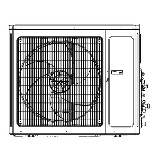
- Page 9 86HM050J245 1087 1015 Fig.2 2). During the transportation of the outdoor unit, two lifting ropes long enough must be used in four directions and the separation included angle must be less than 40°prevent the center of unit deviating. 3). During the installation, M12 screws should be used to fix the support leg and base frame of the unit.
-
Page 10: Connection Between Indoor And Outdoor Units
2.3 Connection between Indoor and Outdoor Units (1). Wiring of the Power Cord CAUTION! A breaker must be installed, capable of cutting off the power supply for the whole system. 1). Open the side plate. 2). Let the power cord go through the rubber ring. 3). - Page 11 Table 3 Allowable Length Refrigerant Pipe Total Length(m) Max. Length for Single Unit(m) Outdoor unit and indoor unit Max. installation altitude Indoor unit and indoor unit Table 4: Dimension of the Refrigerant Pipe of the Indoor Unit unit: mm Capacity Level of the Indoor Unit Gas Pipe Liquid Pipe 09,12...
-
Page 12: Refrigerant Charging And Trial Running
CAUTION! During the connection of the indoor unit and the refrigerant pipe, never pull any joints of the ① . indoor unit by force; otherwise the capillary pipe or other pipe may crack, which then would result in leakage. The refrigerant pipe should be supported by brackets, that is, don’t let the unit withstand the ②... - Page 13 Additional Refrigerant Charge2=∑Extra Liquid Pipe Length×22g/m(liquid pipe). Note: If the total refrigerant pipe length is larger than that listed in the table 7, the additional refrigerant for the extra length of the pipe needs to be charged as per 22g/m. 3). Example : 86HM050J245...
- Page 14 Fig.7 Table 8: Indoor Unit Serial No. Model Indoor Unit ⑤ Ducted Type 85PF009J24 Indoor Unit ④ Ducted Type 85PF009J24 Indoor Unit ③ Ducted Type 85PF009J24 Indoor Unit ② Ducted Type 85PF009J24 Indoor Unit ① Ducted Type 85PF018J24 Table 9: Liquid Refrigerant Pipe Serial No.
- Page 15 (3). Items to be checked after the Installation Table 12 Items to be Checked Possible Errors Check Results Has each part and component of The unit may fall off, vibrate or generate noise. the unit been installed securely? Has the gas leakage test been taken? The cooling (heating) capacity may be poor.
-
Page 16: Working Principles Of The Unit
3 Working Principles of the Unit Schematic Diagram of Inspire Ultra M16 Inverter Heat Pump Multi VRF System Heat Exchanger Liquid Receiver Four-way Valve Capillary Oil Separator Outdoor Unit Stop Valve Compressor Gas/Liquid Separator Electronic Expansion Valve Heating Cooling Indoor Unit Heat Exchanger Heat Exchanger Heat Exchanger... -
Page 17: Parts And Components Of The Unit
4 Parts and Components of the Unit System Structure Outdoor Unit Cassette Type Duct Type Indoor Wall Mounted Duct Type Indoor Indoor Unit Unit(Round air Indoor Unit Unit(Rectangular outlet) air outlet) Fig.9 For the Inspire Ultra M16 air conditioning system, one outdoor unit is able to drive up to five indoor units which can be cassette type, duct type, wall-mounted or floor ceiling type. -
Page 18: Maintenance
(5). Check if the installation of the outdoor is secure. If there is something abnormal, please contact the Delta appointed service center. (6). When restarting the unit which is not used for a long time, switch on the main power supply eight hours ahead, helpful for a successful startup. -
Page 19: Troubleshooting
Do not repair the air conditioning personally but instead contact the professionally skilled ② . personnel at the Delta appointed service center, as the incorrect repair would cause electric shock or fire hazard etc. 6.1 Check before Contacting Service Center Please check the following items before contacting the maintenance serviceman. -
Page 20: Problem Handling
6.2 Problem Handling The conditions listed below are not classified into errors. Table 14 Conditions Causes When restart the unit soon after it is The overload protection switch of the unit stopped. let the startup delayed for three minutes. The unit does not run The unit will stand by for approximate one As soon as power is on. - Page 21 High Discharge Flash 4 times Outdoor Temp Protection Outdoor & Communication Error Flash 6 times Indoor Indoor Unit Water Flash 9 times Indoor Full Error Refrigerant Quick Quick Special Mode Recovery Mode Flashing Flashing Outdoor Ambient Flash 3 times Outdoor Temp Sensor Error Outdoor Mid-Coil Flash 4 times...
- Page 22 Flash 21 Low Voltage Protection Drive Error times Temp Drift Protection Flash 3 times Flash 3 times Flash 3 times Drive Error Drive Board Ambient Flash 3 times Flash 3 times Flash 3 times Drive Error Temp Sensor Error AC Current Protection Flash 5 times Drive Error Flash 17...
- Page 23 Outdoor Ambient Flash 3 times Outdoor Temp Sensor Error Outdoor Mid-Coil Flash 4 times Outdoor Temp Sensor Error Outdoor Discharge Air Flash 5 times Outdoor Temp Sensor Error Oil Return for Cooling Flash 7 times Special Mode Quick Forced Defrosting Special Mode Flashing Oil Return for Heating...
- Page 24 Unit n indoor pipe midway temperature Flash twice Indoor Table 16 sensor error Indoor Evaporator Temp Sensor Short/ Flash twice Indoor Table 16 Open-Circuit (Air Valve) Unit n indoor unit pipe Flash 22 times Indoor outlet temperature Table 16 sensor error (Liquid Valve) Unit n indoor pipe Flash 19 times...
-
Page 25: After-Sales Service
Once errors are displayed on the controller, please shut off the air conditioning unit and contact the professionally skilled personnel for troubleshooting. 6.4 After-Sales Service If there is any quality or other issue, place contact the Delta after-sales service center. -
Page 26: Function Description
7 Function Description Forcible Defrosting How to activate this function: when indoor unit runs under the HEAT mode and at 16℃ , it will activate the forcible defrosting by pressing the “+”and “-” buttons alternately three times in five seconds. How to quit this function: the function will quit when the mode of indoor units conflict. -
Page 27: Performance Parameters
8 Performance Parameters Rated Working Conditions of the Air Conditioning Unit Table 18 Working Temperature Range Indoor side state Outdoor side state Dry bulb temp. ℃ Wet bulb temp. ℃ Dry bulb temp. ℃ Wet bulb temp. ℃ Rated Cooling Max. - Page 28 Thank you for Choosing airconditioners Perfectly engineered for your comfort. www.delta-dct.com...
Need help?
Do you have a question about the 86HM050J245 and is the answer not in the manual?
Questions and answers